Geometric cleaning, mid surface extraction and meshing using Hypermesh
OBJECTIVE:
To cleanup and extract the midsurface of the given gometries. To 2D mesh the given geometries in accordance with the quality criterias given below and to assign thickness by creating a generic property.
Minimum Element Size: 3.5mm
Target Element Size: 5mm
Maximum Element Size: 7mm
PROCEDURE:
For part 1
1. Import the given geometry using Hypermesh
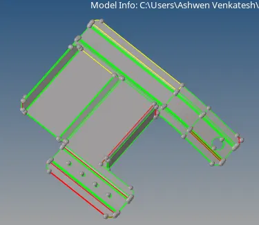
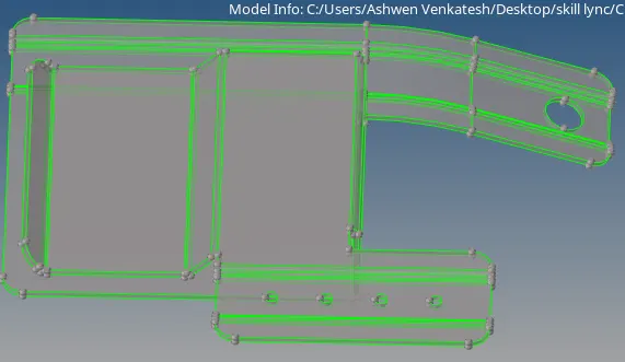
2. Change the geometric color view to "By Topo" to check for geometrical errors over the geometry.
3. The geometrical errors are fixed using quick edit and surface edit options. These are shown in the figures below.
4. After the geometrical cleanup go to Geom>>midsurface>>select the surfaces>>extract.
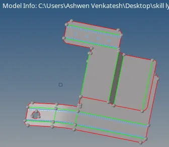
5. Check for any errors over the extracted midsurface and fill the holes with diameter less than 5 mm using surface option. By using quick edit and defeature option the midsurface is cleaned up. The final midsurface is shown in the figure below.
6. After extracting the midsurface go to 2D>>automesh>>size and bias>>element size 5mm>>select surfs>>mesh.
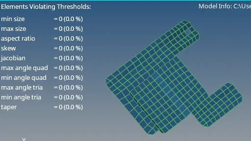
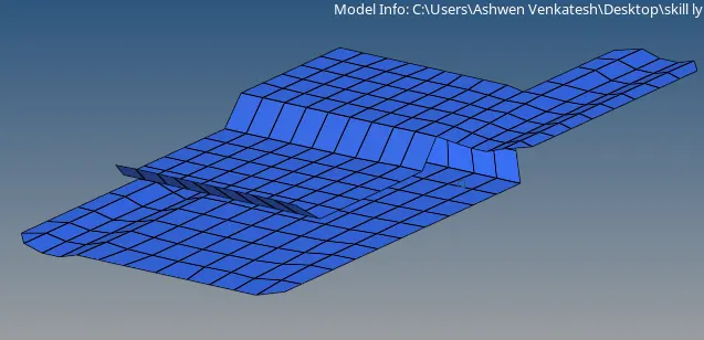
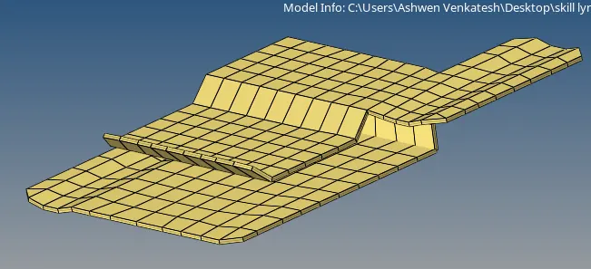
7. After meshing check for the quality criteria of the mesh. If the quality criteria is not satisified, cleanup tools are used to arrive at the given quality criterias and to obtain proper mesh flow. This is shown in the figure below.
8. After meshing, go to components view tab>>create>>material>>steel.
9. Go to components view tab>>create>>property>>assign the thickness.
10. The final meshed model in detailed 2D element representation is shown in the figure below.
For part 2
1. Import the given geometry using Hypermesh
2. Change the geometric color view to "By Topo" to check for geometrical errors over the geometry.
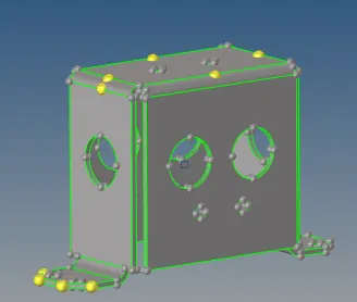
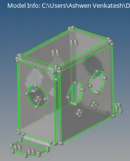
3. The geometrical errors are fixed using quick edit and surface edit options. These are shown in the figures below.
4. After the geometrical cleanup go to Geom>>midsurface>>select the surfaces>>extract.
5. Check for any errors over the extracted midsurface and fill the holes with diameter less than 5 mm using surface option. By using quick edit and defeature option the midsurface is cleaned up. The final midsurface is shown in the figure below.
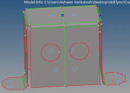
6. After extracting the midsurface go to 2D>>automesh>>size and bias>>element size 5mm>>select surfs>>mesh. Since the geometry is symmetrical is with respect to axis, the meshing is done in a single side and reflected along the symmetrical axis using the base point.
7. After meshing check for the quality criteria of the mesh. If the quality criteria is not satisified, cleanup tools are used to arrive at the given quality criterias and to obtain proper mesh flow. This is shown in the figure below.
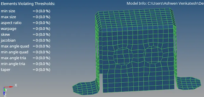
8. After meshing, go to components view tab>>create>>material>>steel.
9. Go to components view tab>>create>>property>>assign the thickness.
10. The final meshed model in detailed 2D element representation is shown in the figure below.
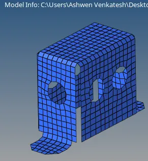
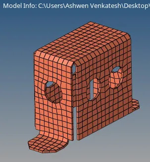
For part 3
1. Import the given geometry using Hypermesh
2. Change the geometric color view to "By Topo" to check for geometrical errors over the geometry.
3. The geometrical errors are fixed using quick edit and surface edit options. This is shown in the figure below.

4. After the geometrical cleanup go to Geom>>midsurface>>select the surfaces>>extract.
5. Check for any errors over the extracted midsurface and fill the holes with diameter less than 5 mm using surface option. By using quick edit and defeature option the midsurface is cleaned up. The final midsurface is shown in the figure below.
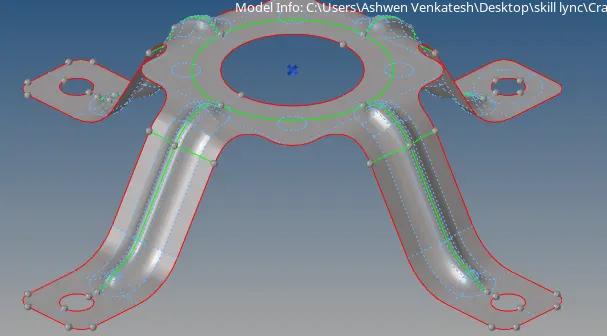
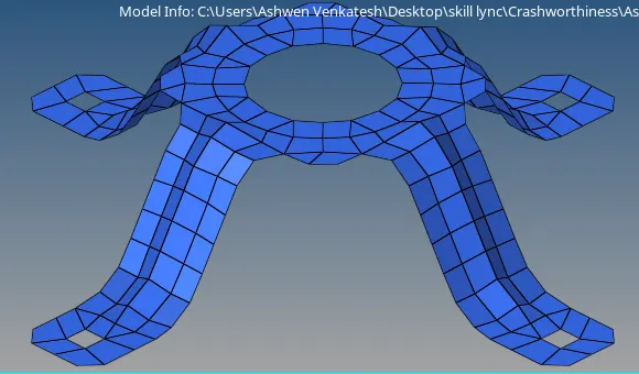
6. After extracting the midsurface go to 2D>>automesh>>size and bias>>element size 5mm>>select surfs>>mesh. Since the geometry is symmetrical is with respect to axis, the meshing is done in a single side and reflected along the symmetrical axis using the base point.
7. After meshing check for the quality criteria of the mesh. If the quality criteria is not satisified, cleanup tools are used to arrive at the given quality criterias and to obtain proper mesh flow. This is shown in the figure below.
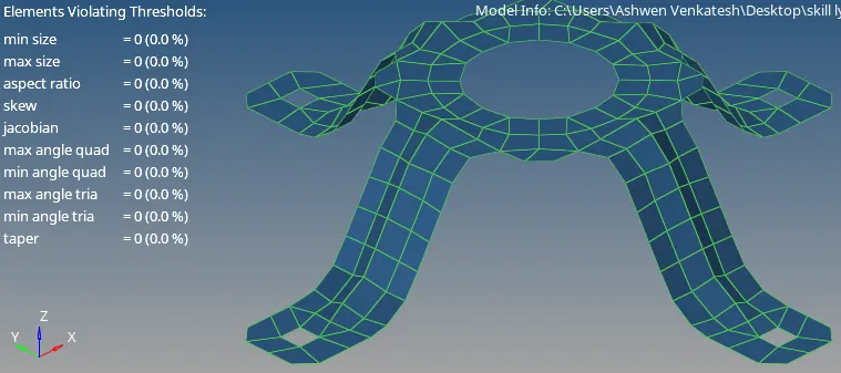
8. After meshing, go to components view tab>>create>>material>>steel.
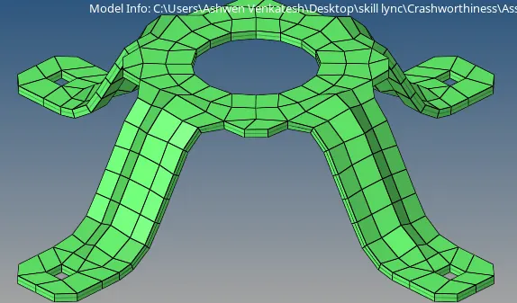
9. Go to components view tab>>create>>property>>assign the thickness.
10. The final meshed model in detailed 2D element representation is shown in the figure below.
RESULTS AND CONCLUSION:
The given geometries is cleaned up and mid surface is extracted. The 2D meshing is done in accordance with the given quality criteria given and suitable thickness is assigned.
Drive link: https://drive.google.com/file/d/1z3AcTxQzQzgwPSmlmYXe94nFf4KpPOwH/view?usp=sharing