Week 14 challenge
ASSEMBLY OF THE BUTTERFLY VALVE
A Butterfly valve regulates the flow by starting slowing or stopping a media. The disc opens and closes with a low torque of 90 and works on any compactible applications. Because of their low cost and maintenance the butterfly valve is preferred over the other valves.
The assembly of butterfly valve includes body , shaft ,retainer , disc, lever , bolts and a nut.
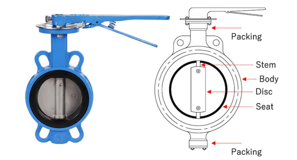
The parts are created one by one are are saved individually .
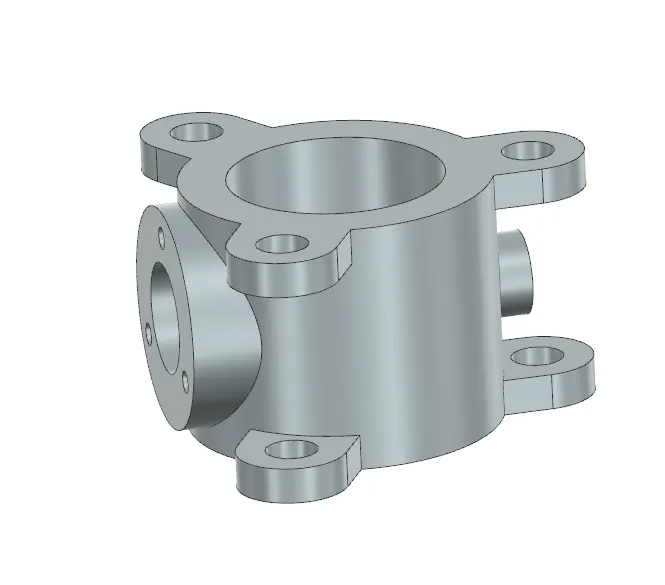
The body
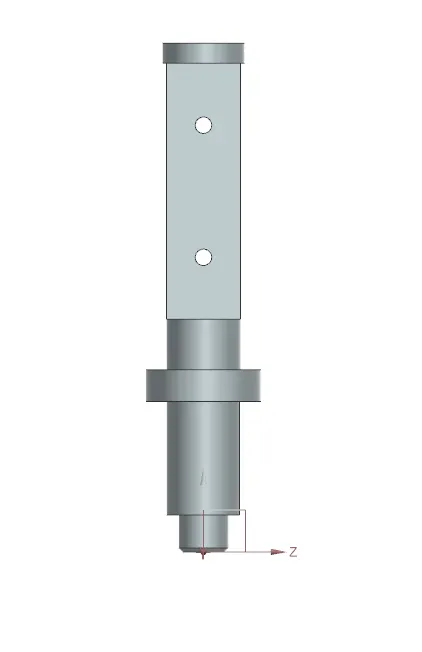
The shaft
The lever
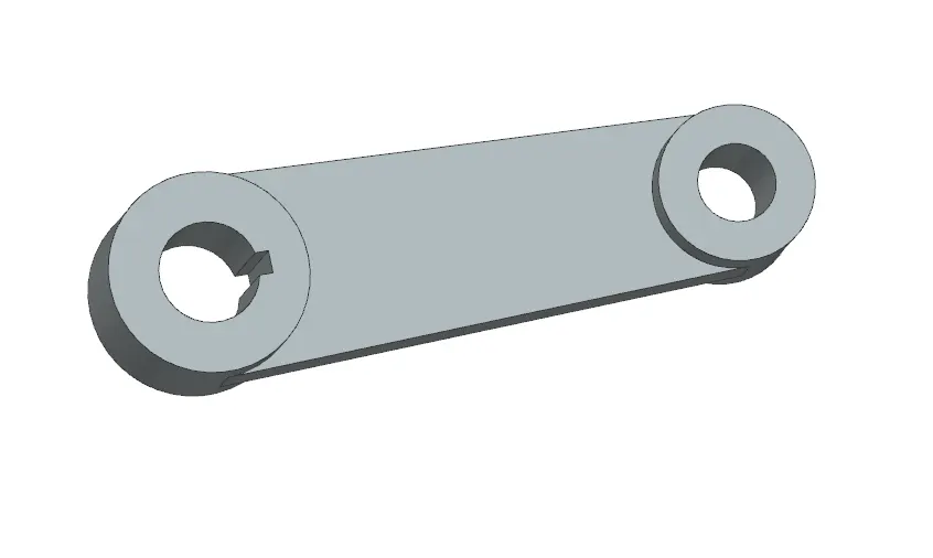
The retainer
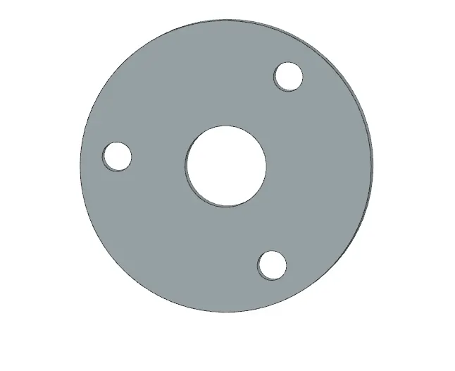
The disc
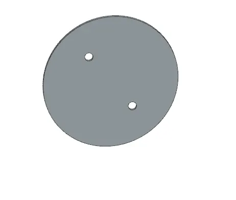
The nut
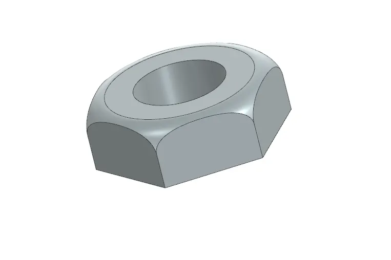
The bolt
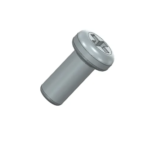
The GD and T of the parts are also done using the drafting bench in siemens NX.
ASSEMBLY OF THE PARTS
A file is created and a new assembly workbench is opened and the parts are added one by one to the assembly workbench.
To add the part we can select add component in the assembly work bench
The parts are added and each have seperate coordinate system and we have to assemble them using different tools in the assembly workbench.
The components added are shown below
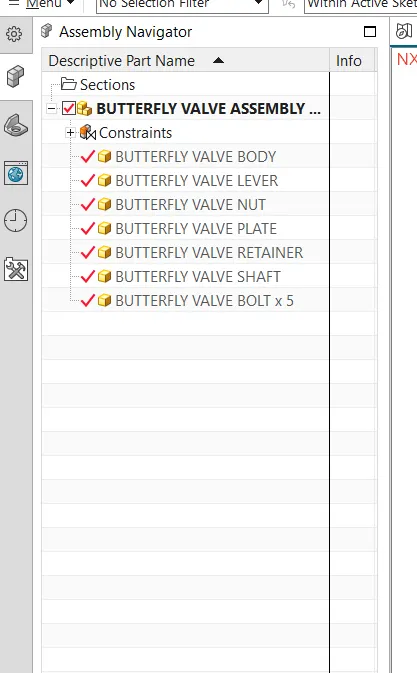
The parts are arranged using different constrains such as touch constrain , align constrain ,
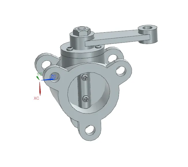
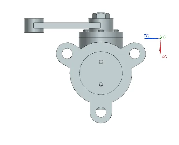
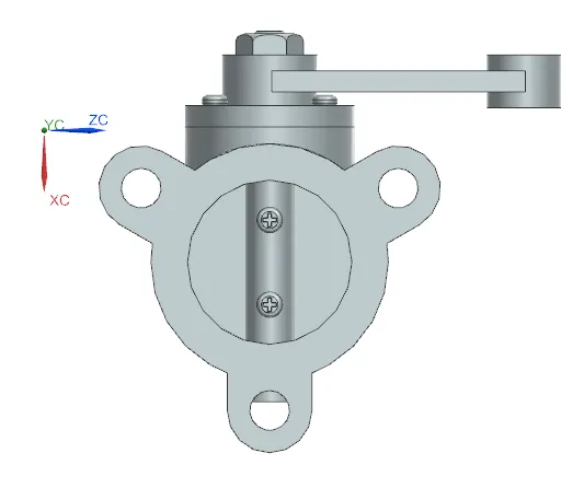
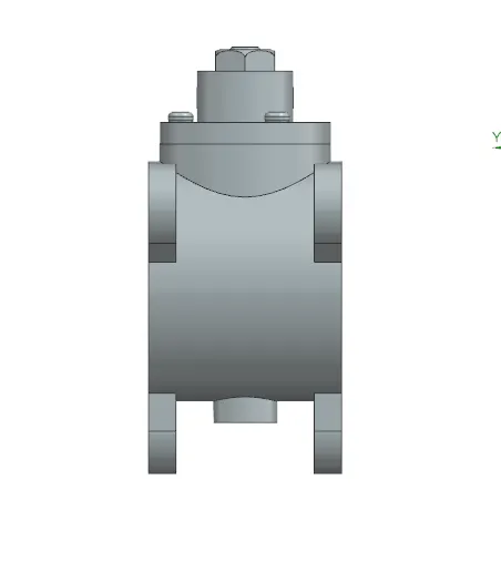
The body is firstly alligned to make other components to assemble on it. The final output of the assembly is shown below.
APPLYING GD AND T TO THE ASSEMBLY
To apply GD and T we need to know about the operation of the assembly and the crucial part in the assembly.
All the other parts a have been included in the previous projects , the remaining main part is the main body of the butterfly valve.
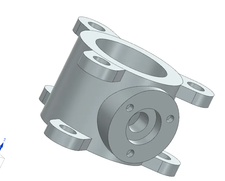
The flow direction is shown as
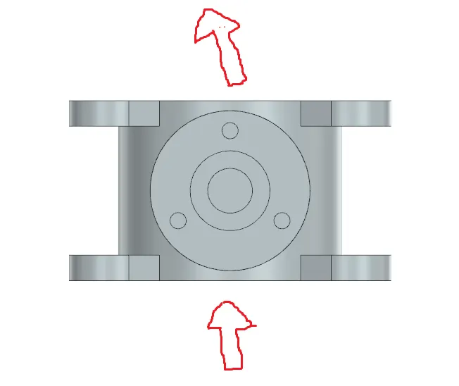
The butterfly valve is attached to the pipe at one end like this end in the figure.
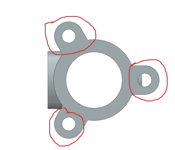
These areas play an important role in the functioning. So GD and T are important for the part , These areas can be given as datum target area like A1 A2 and A3. THe datum areas are given a flatness tolerance.
The opposite side having same attachment is also important one, so we can give the profile to the surface with respect to the datum A ( A1 A2 A3).
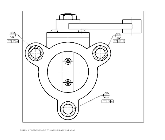
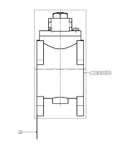
Then there are remaining two datums to be given, to constrain the part that is datum B and C.
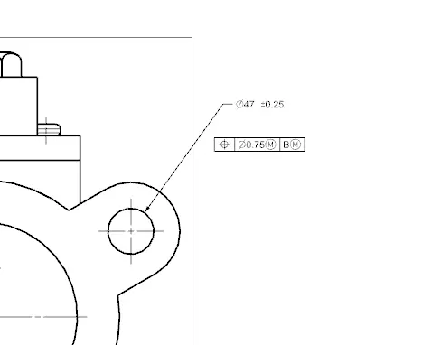
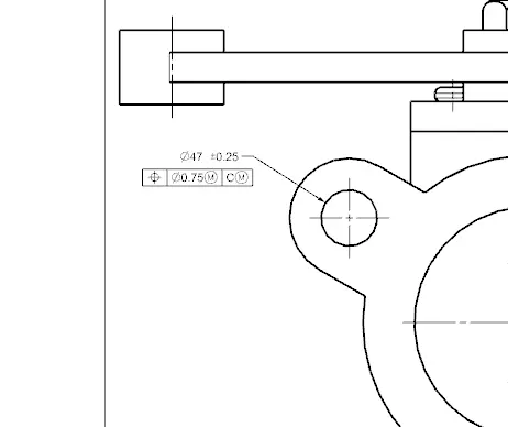
The B datum can be one of the hole in the datum target areas and B can be the another hole in the part, the datums are given perpendicularity and position tolerance as well
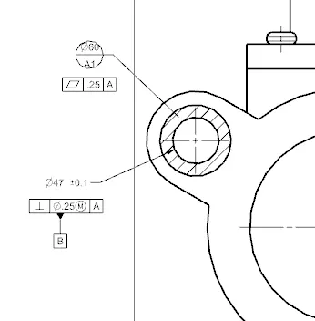
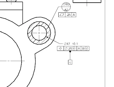
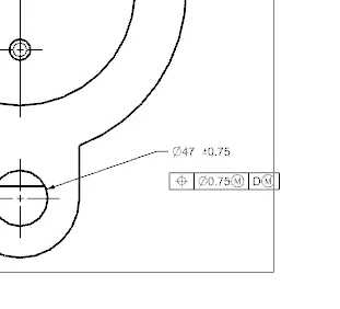
We also have to consider the opposite side holes so we need to give a sub datum D to the third hole and can give tolerance with respect to B , C and D datums.
The position tolerance is given to the holes on the other side of the part. The figure is given below.
There are other parts like to give tolerance example like the rod of the lever, there is no need because it is not in the function and the slight variation in dimension do not affect the operation of the valve.
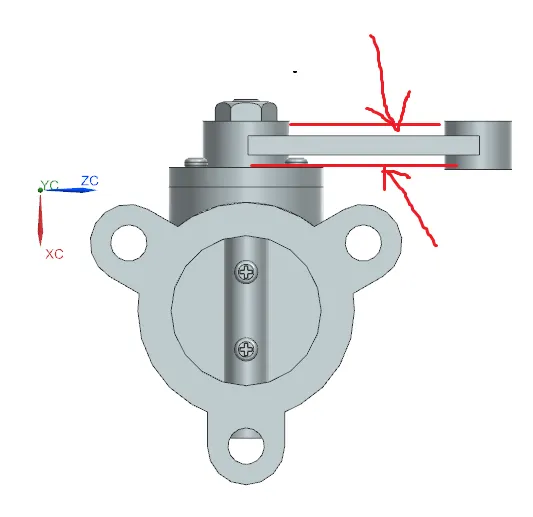
The variation of thickness on the marked region do not affect the operation and is of less important. The part only need to give size tolerance.