Project - Analysis of a practical automotive wiring circuit
1
The major elements in the diagram are
- Horn button
The "horn button" generally refers to the button in a vehicle that activates the horn, alerting others through a loud sound. It is usually located at the centre of the steering wheel or integrated into it. In some cases, especially in custom or older vehicles, the horn button might be mounted separately on the dashboard or steering column.
- Tail stop
The term "tail stop" typically refers to the tail light and brake light system at the rear of a vehicle. When you press the brake pedal, the brake lights (tail stop lights) illuminate, signalling to drivers behind you that you're slowing down or stopping.
- Light switch
A light switch is a device used to control the flow of electricity to a light fixture, turning it on or off. It is a common feature in homes, vehicles, and machinery, allowing users to control lighting with ease.
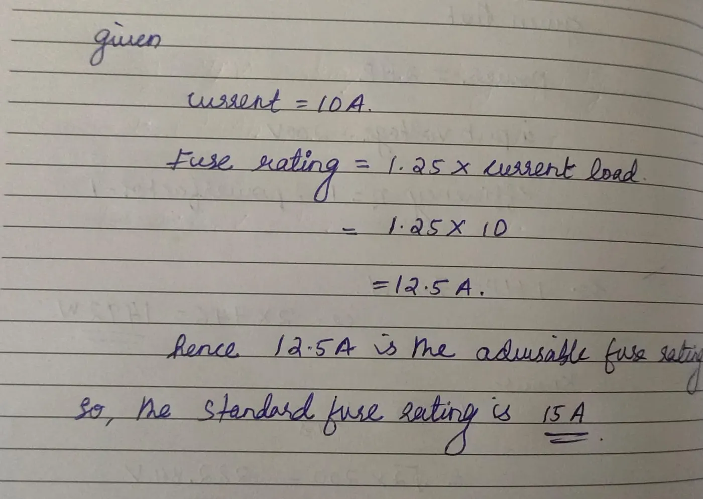
- Fuse
A fuse is a safety device used in electrical circuits to protect them from overcurrent . It contains a metal wire or strip that melts when too much current flows through it, thereby interrupting the circuit and preventing damage to the electrical components or even fire hazards. Once the fuse "blows" or melts, it needs to be replaced to restore the circuit's functionality.
- Ammeter
An ammeter is an electrical instrument used to measure the current flowing through a circuit. It helps in diagnosing electrical systems by indicating much current is being consumed or generated. Ammeters are commonly used in both automotive systems and general electrical testing.
- Battery
A battery is an energy storage device that converts chemical energy into electrical energy to power electrical devices. Batteries come in various shapes, sizes, and types, and are used in everything from small electronic devices to large automotive systems.
- Starter
A starter is a device in an internal combustion engine that initiates the engine’s operation by turning the engine over until it can run on its own. In vehicles, the starter engages with the engine’s flywheel to get the engine’s components moving, such as the crankshaft and pistons, allowing the combustion process to begin.
- Foot selection switch
A foot selection switch typically refers to a foot-operated switch used to control different settings or functions in equipment, vehicles, or machinery. These switches are designed for hands-free operation, allowing users to keep their hands on other controls while selecting different modes or functions with their foot.
- ignition coil
An ignition coil is a critical component in a vehicle’s ignition system that converts the low voltage from the car’s battery into the high voltage necessary to create a spark at the spark plugs, which ignites the air-fuel mixture in the engine cylinders. Essentially, the ignition coil acts as a transformer, boosting the voltage to thousands of volts.
- Distributor
A distributor is a component in older internal combustion engines that plays a key role in the ignition system. Its primary function is to route the high-voltage electricity from the ignition coil to the correct spark plug in the correct sequence, ensuring that the air-fuel mixture in the engine's cylinders ignites at the right time.
- Generator
A generator is a device that converts mechanical energy into electrical energy using the principles of electromagnetic induction. Generators are used in various applications, from providing backup power to homes and businesses to supplying electricity in remote locations and driving industrial equipment.
- Junction block
A junction block is an electrical component used to connect multiple electrical circuits or wires together in a neat and organized manner. Junction blocks are commonly found in various electrical and automotive applications. They serve to distribute power, manage connections, and ensure safe and reliable electrical systems.
2 Explain the working of any three elements briefly
- FUSE
A fuse is a safety device used in electrical circuits to protect them from overcurrent . It contains a metal wire or strip that melts when too much current flows through it, thereby interrupting the circuit and preventing damage to the electrical components or even fire hazards. Once the fuse "blows" or melts, it needs to be replaced to restore the circuit's functionality.
Components of a Fuse
- Fuse Element: The thin metal wire or strip inside the fuse that melts when the current exceeds its rated value.
- Fuse Body: The insulating material that houses the fuse element, often made of glass or ceramic.
- End Caps: The metal parts at each end of the fuse that make electrical contact with the circuit.
- Housing: The outer casing that holds the fuse element and provides protection.
How a Fuse Works
Normal Operation: During normal operation, the current flowing through the fuse is within its rated capacity. The fuse element conducts the current without any issues, and the circuit remains closed.
Overload Condition: If the current flowing through the circuit exceeds the fuse’s rated capacity, the fuse element starts to heat up due to increased resistance.
Melting Point: The fuse element have a specific melting point. When the current exceeds the fuse’s rating, the heat generated causes the fuse element to melt.
Breaking the Circuit: As the fuse element melts, it creates an open circuit by breaking the electrical connection. This interruption stops the flow of current, thereby protecting the circuit from potential damage.
Replacement: Once a fuse has blown, it must be replaced with a new one of the same rating to restore the circuit's functionality. Fuses are designed to be single-use and must be replaced when they blow.
- AMMETER
An ammeter is an electrical instrument used to measure the current flowing through a circuit. It helps in diagnosing electrical systems by indicating much current is being consumed or generated. Ammeters are commonly used in both automotive systems and general electrical testing.
Components of an ammeter
- Measuring Coil: In many ammeters, especially analogue ones, a coil is used to measure current. This coil creates a magnetic field proportional to the current passing through it.
- Moving Needle (Analog Ammeter): In analogue ammeters, the current passing through the coil generates a magnetic field that causes a needle to move across a scale, indicating the current.
- Digital Display (Digital Ammeter): In digital ammeters, the current is converted into a digital signal and displayed on a digital screen.
How an Ammeter works
- Power Off: Ensure the circuit is powered off before connecting the ammeter to prevent any accidental short circuits or damage.
- Series Connection: Connect the ammeter in series with the circuit. This means breaking the circuit and inserting the ammeter so that the current flows through the device
- Select Range: If using a multi-range ammeter, select the appropriate current range based on the expected current.
- Power On: Turn on the circuit and read the current value from the ammeter’s display or scale.
- BATTERY
A battery is an energy storage device that converts chemical energy into electrical energy to power electrical devices. Batteries come in various shapes, sizes, and types, and are used in everything from small electronic devices to large automotive systems.
Components of a Battery
- Anode: The negative electrode where oxidation occurs.
- Cathode: The positive electrode where reduction occurs.
- Electrolyte: The substance that facilitates the flow of ions between the anode and cathode, enabling the chemical reactions.
- Separator: A material that prevents direct contact between the anode and cathode while allowing ions to pass through.
- External Circuit: The path through which the electrical current flows from the battery to the external device.
- STARTER
A starter is a device in an internal combustion engine that initiates the engine’s operation by turning the engine over until it can run on its own. In vehicles, the starter engages with the engine’s flywheel to get the engine’s components moving, such as the crankshaft and pistons, allowing the combustion process to begin.
Components of a Starter
- Electric Motor: The heart of the starter, responsible for turning the engine.
- Solenoid: Acts as a relay that closes the circuit to send power from the battery to the motor.
- Pinion Gear: Engages with the engine's flywheel to crank the engine.
- Flywheel: A large, toothed wheel attached to the engine’s crankshaft. The pinion gear engages with the flywheel to rotate the crankshaft and start the engine.
- Battery: Supplies the electrical power required to run the starter motor.
Working of a Starter
- Ignition Switch : When you turn the key or press the start button, it sends an electrical signal to the starter solenoid.
- Solenoid Engagement: The solenoid, acting as a switch, engages and allows a large amount of electrical current to flow from the battery to the starter motor.
- Pinion Gear Engagement: The solenoid also pushes the small pinion gear on the starter shaft into engagement with the teeth of the flywheel on the engine. This ensures that the starter motor can transfer its rotational force to the engine.
- Cranking the Engine: Once the pinion gear is engaged with the flywheel, the electric motor of the starter begins to turn. This rotates the flywheel, which in turn rotates the engine’s crankshaft. This cranking motion gets the engine moving, allowing it to begin its own combustion cycle.
- Engine Starts Running: Once the engine has started and is running on its own power, the solenoid disengages, pulling the pinion gear away from the flywheel. This prevents the starter motor from continuing to turn once the engine is running.
- Starter Disengages: After the engine starts, the starter motor stops, and the pinion gear retracts from the flywheel, leaving the engine to run under its own power.
3
4
5
The elements connected in parallel are
Headlights: Both the left and right headlights are connected in parallel, so if one fails, the other continues to function.
Tail lights, brake lights, and indicator lights: These lights are connected in parallel to ensure independent operation.
They are connected in parallel because ,
- Independent Operation: Each component in a parallel circuit can function independently. If one component fails (e.g., one headlight or tail light), the others remain operational.
- Consistent Voltage: In a parallel configuration, all components receive the same voltage (typically 12V or 24V in automotive systems). This is important because most automotive components are designed to operate at a specific voltage.
6
The elements connected in series are
Battery cells Individual cells in a battery pack are connected in series to increase the overall voltage.
Warning lights Warning lights like seatbelt or airbag warning indicators may have a resistor connected in series with the light.
They are connected in series because ,
- Voltage Division:
In series circuits, the total voltage is divided across components. This property is useful when different parts of a system require less voltage than the total supply.
Current Limiting:
In a series connection, the same current flows through all components. By adding resistors or other current-limiting devices in series with sensitive components, the current is controlled, preventing damage.