Advanced Sheet Metal Design Using NX Cad Challenge_6_Bracket
BRACKET DESIGNING
In sheet metal work, a bracket typically refers to a support piece used to hold or secure different parts together. Brackets can be made from various types of sheet metal, such as steel, aluminium, or stainless steel, and they come in various shapes and sizes depending on their intended use.
Here are some common types of brackets used in sheet metal work:
- Angle Brackets: These are L-shaped brackets used to join two parts at a right angle.
- Z-Brackets: These brackets have a Z shape and are used to provide offset mounting points.
- U-Brackets: These are U-shaped and are used to hold or support round objects like pipes or cables.
- Gusset Brackets: These brackets provide extra support to a joint, often used in construction or heavy-duty applications.
- Mounting Brackets: Used to mount components or devices to a surface.
The design and fabrication of sheet metal brackets involve several processes, including:
- Cutting: Using tools like shears, lasers, or plasma cutters to cut the metal to the desired shape.
- Bending: Using press brakes or other bending machines to form the metal into the required shape.
- Punching: Creating holes or cut outs in the metal using punch presses.
- Welding: Joining different parts of the bracket together using welding techniques.
- Finishing: Applying surface treatments like painting, powder coating, or galvanizing to protect the metal and enhance its appearance.
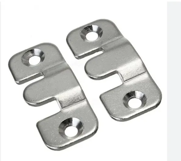
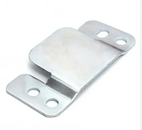
THE STEPS FOLLOWED IN MODELLING ARE
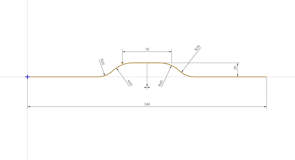
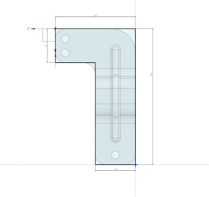
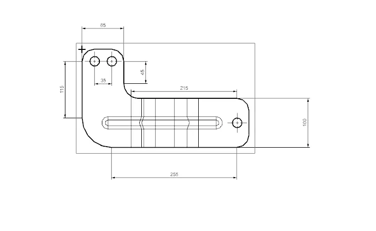
- Creating the sketch for Counter flange with appropriate fillets and lengths and dimensions.
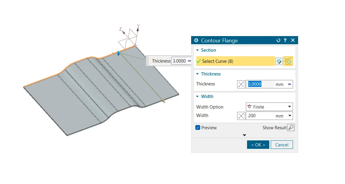
- Selecting the counter flange command from the task bar and giving appropriate dimensions and direction.
- Making the sketch for normal cut out for getting the desired shape for the piece on which the bracket to be formed.
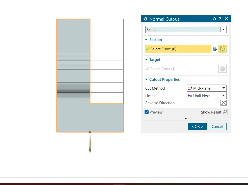
- Selecting the normal cut out from the taskbar and giving the appropriate dimensions for the cut out.
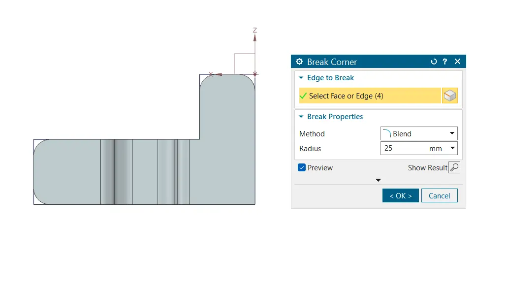
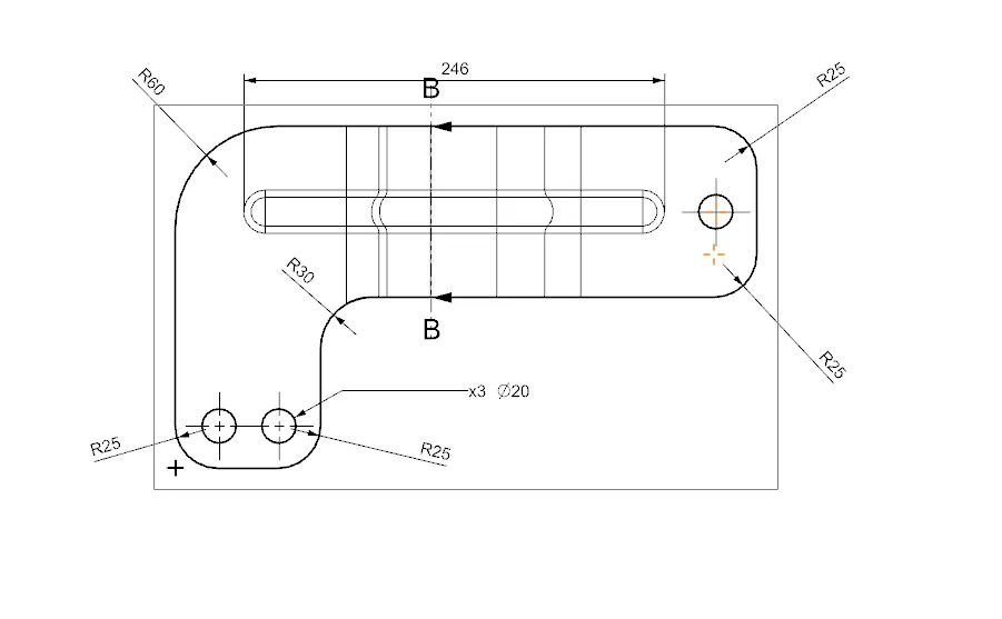
- Applying break corner command to the cut out created. The radius of 25 mm is given .
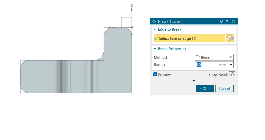
Here the radius of 30 mm is applied.
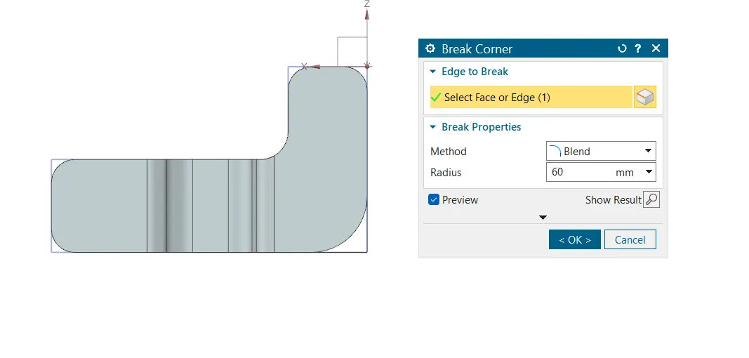
The radius of 60 mm is applied here.
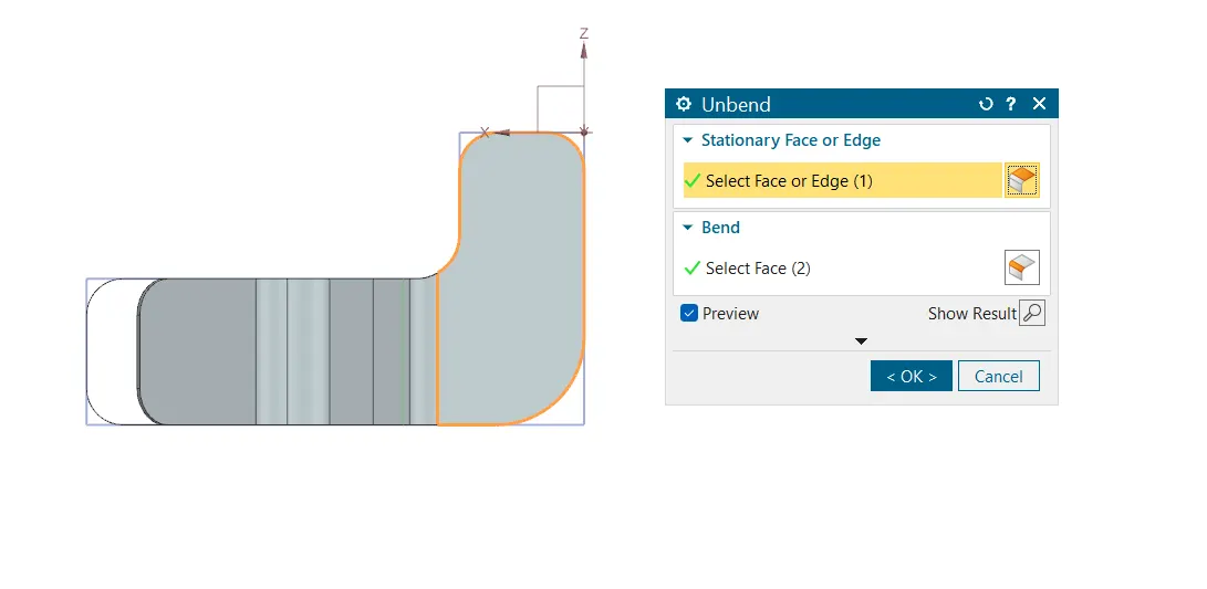
- Un bending the sheet part for checking the reversibility of the sheet. By un bending the part we can check for the reversibility and also we can give the beads and holes .
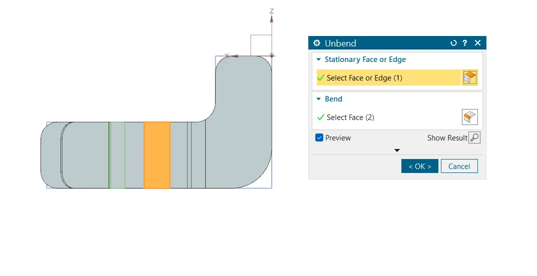
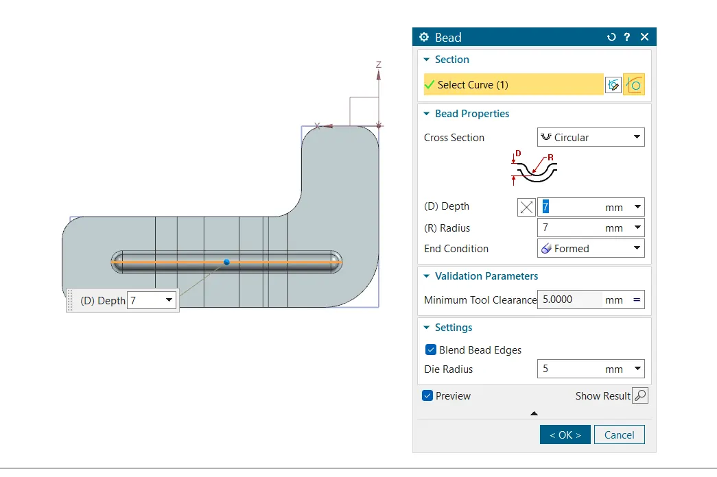
- Adding the bead command to the flat part , We need to unbend the part before adding a bead to get proper bead.
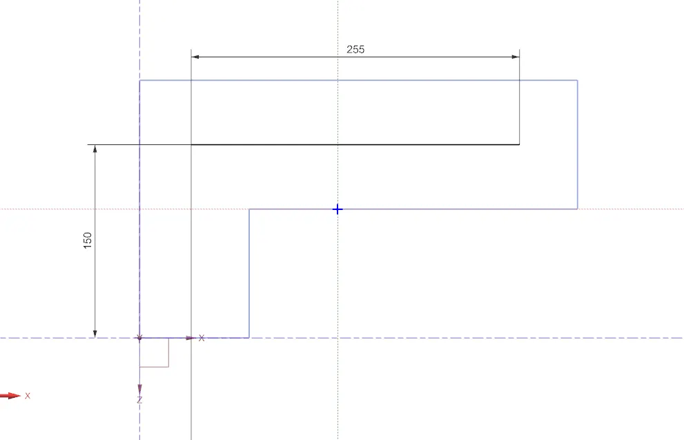
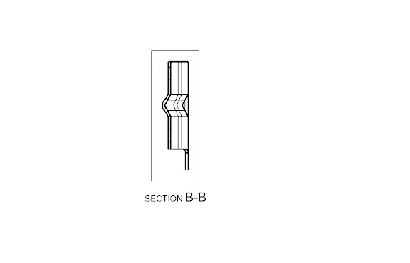
Applying the bead command to the sketch. The depth and radius should be the same and die radius of 5 mm is given.
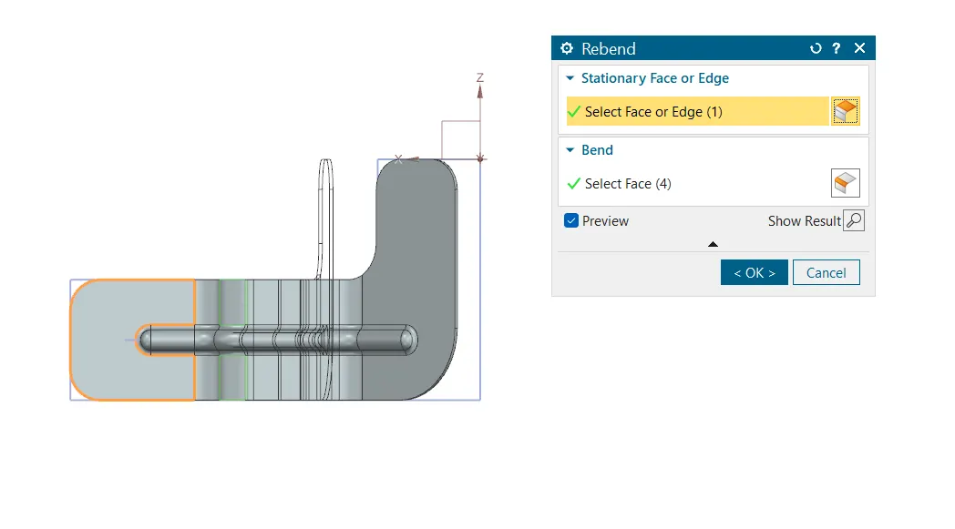
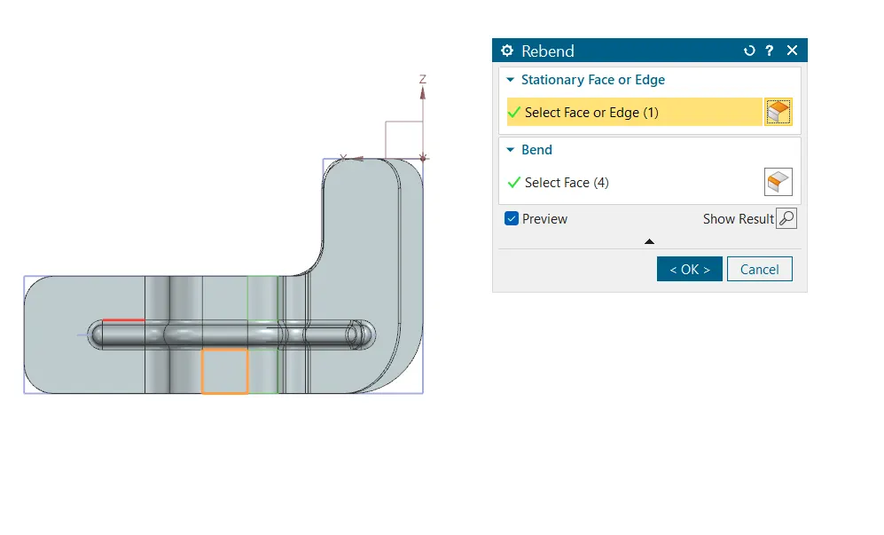
- Re bending the part to make the required shape before the bead is added.
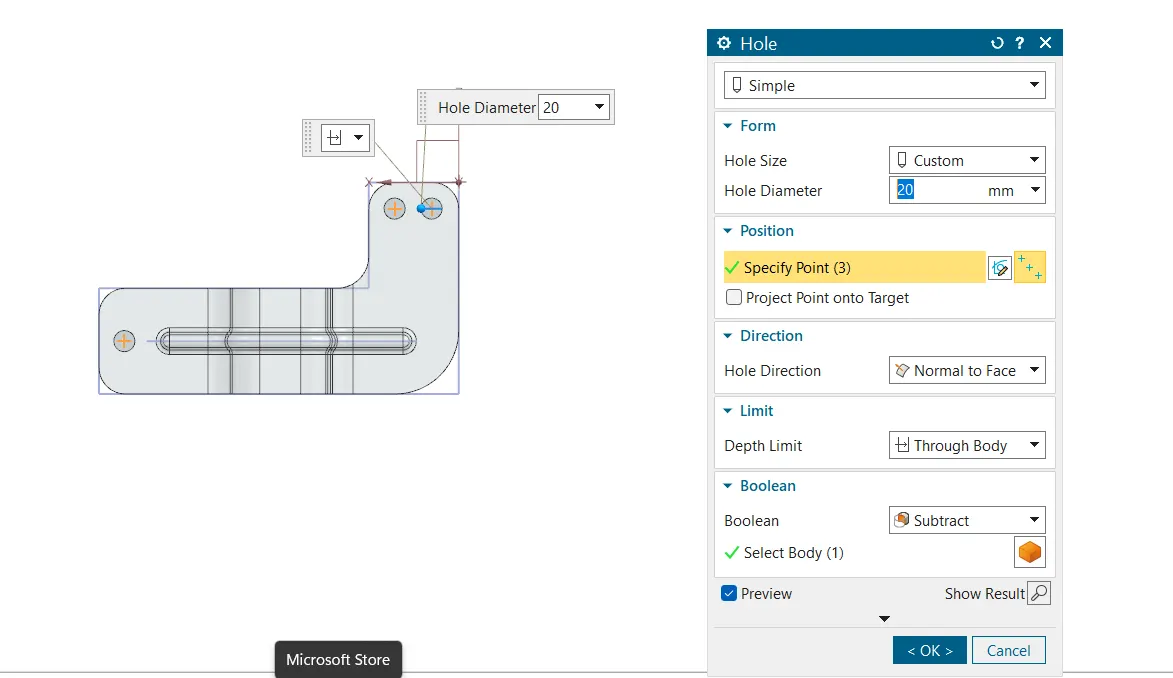
- Adding holes to the un bended sheet. The hole of diameter 20 mm and normal; to face is added and subtract is used as boolean command.
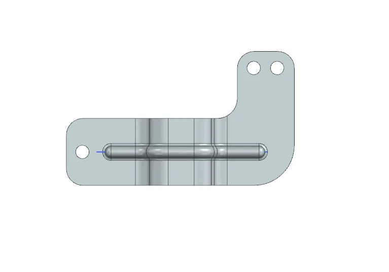
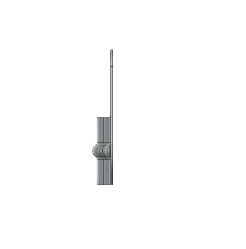
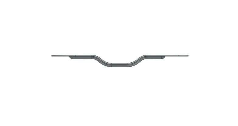
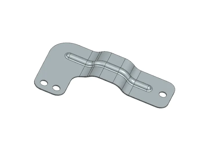
The final part made is given below
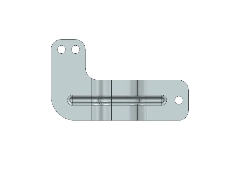
SOME VIEWS OF THE PART
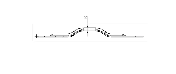
DRAFTING THE SHEET PART
DESCRIPTION OF THE COMMANDS USED IN THE SHEET METAL OPERATION
- Counter Flange
In Siemens NX, the "Counter Flange" command is used to create a flange feature on sheet metal parts. A flange is a projecting flat rim, collar, or rib on an object, serving for strengthening or attachment. The Counter Flange command allows you to create a flange that is positioned opposite or in relation to an existing flange.
- Break Corner
The "Break Corner" command is used to create rounded or chamfered corners on a part. This command is particularly useful for improving the aesthetics, safety, and manufacturability of parts by eliminating sharp edges.
- Normal Cut out
In Siemens NX, the "Normal Cut Out" command is used to create a cut or slot through a solid body that is normal (perpendicular) to a selected face.
- Bend
In Siemens NX, The bend command is used to create a bend in the sheet metal part.
- Un Bend
In Siemens NX, The unbend command is used to unbend in the sheet metal part.
- Re Bend
In Siemens NX, The Re bend command is used to bend in the sheet metal part to its previous state.
- Bead
In Siemens NX, the Bead command is used to create stiffening features on sheet metal parts. These features, also known as beads, enhance the rigidity and strength of the sheet metal without significantly increasing its weight. The Bead command is a common tool in the design of automotive, aerospace, and other sheet metal components where structural integrity is crucial.
- Hole
In Siemens NX, the "Hole" command is used to create various types of holes in solid bodies. This command is versatile and can be used for creating simple, counterbored, countersunk, and threaded holes.