Week 10 - Challenge 1- Attachment Feature Creation (Ribs & Screw Boss)
ATTACHMENT FEATURE CREATION - RIBS AND SCREW BOSS
From the given Class A surface, the component should be created as a closed body. Along with that, ribs and screw boss should also be attached to the body as per the design rules prescribed for them.
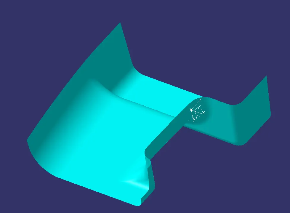
Fig 1. Class A Surface.
The given Class A surface is initially checked using Boundary command and found no gaps are on the surface.
The next step is tooling axis creation.
Tooling Axis Creation
Tooling Axis is created using bisecting method. In this design, tooling axis is created along Y direction.
- An extract of the flat portion is taken
- A point is created at the centre of the extract and an axis system is created at that point.
- The intersection of the axis system and the surface is taken.
- Two lines are constructed along the side wall and their bisecting line is taken and considered as the temperory tooling axis.
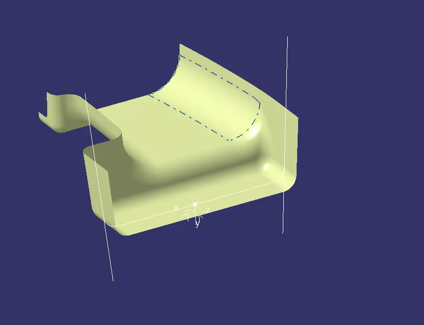
- Fig 2. Tooling axis creation.
Draft Analysis on Class A surface
Draft analysis is done on the given Class A surface and checked whether the Class A surface clears the draft with the tooling axis considered before.
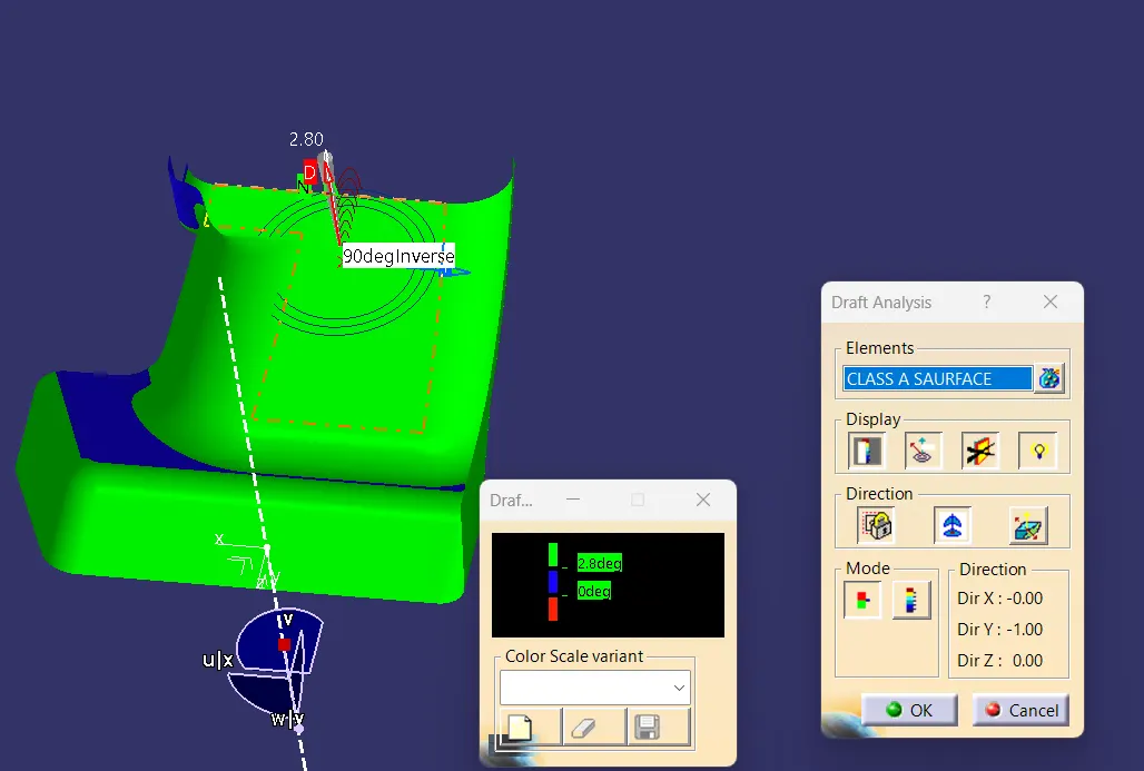
Fig 3. Draft analysis on Class A surface.
Steps for draft analysis:
- In the view mode asection , select customize view parameters and select material option.
- Select feature draft analysis command.
- Select the compass icon and place the axis system that appears along the tooling axis.
- Using the colors, check whether the part clears the draft.
Here the part cleared the draft and the tooling axis taken is almost satisfied correctly.
Creation of Class B surface
Since the Class A surface is a complex surface, the surface is offseted completely by 3mm inwards to create Class B. While checking the offseted B surface, it was found that a part of the surface went missing due to it fillets and comples structure.
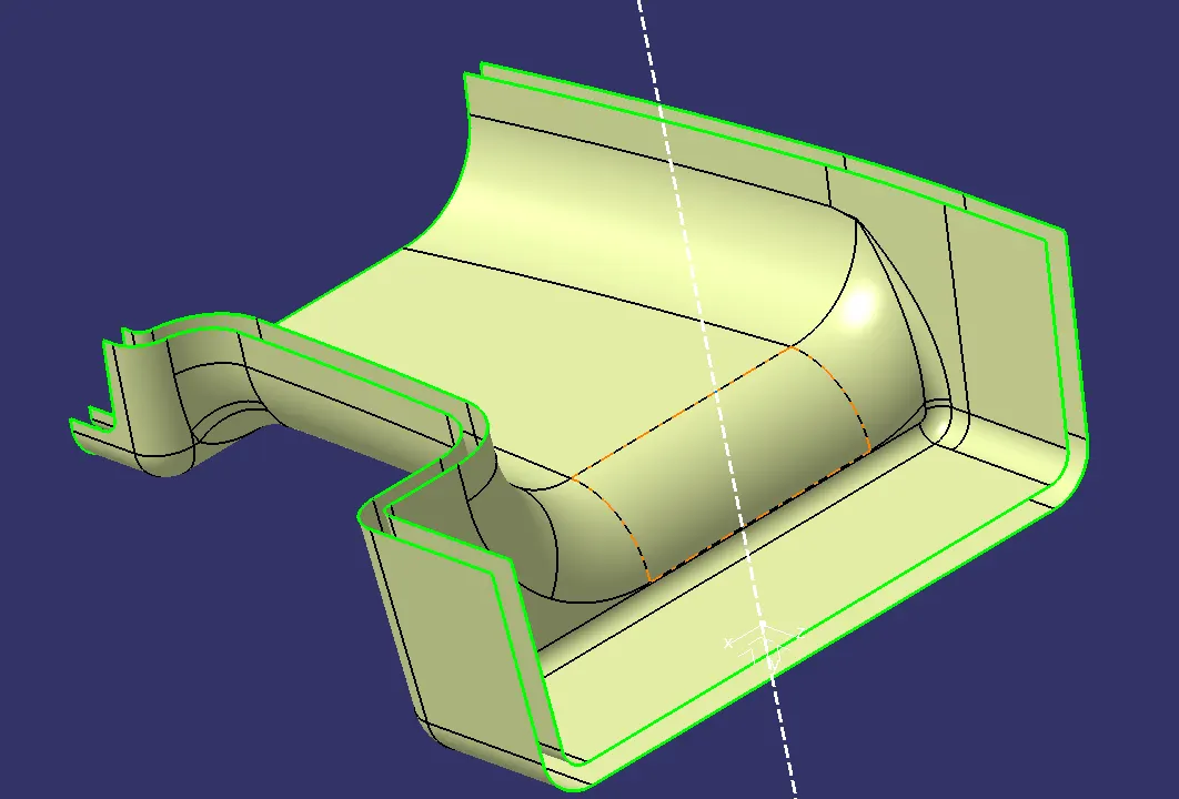
Fig 4. Offsetting class A surface and a part .
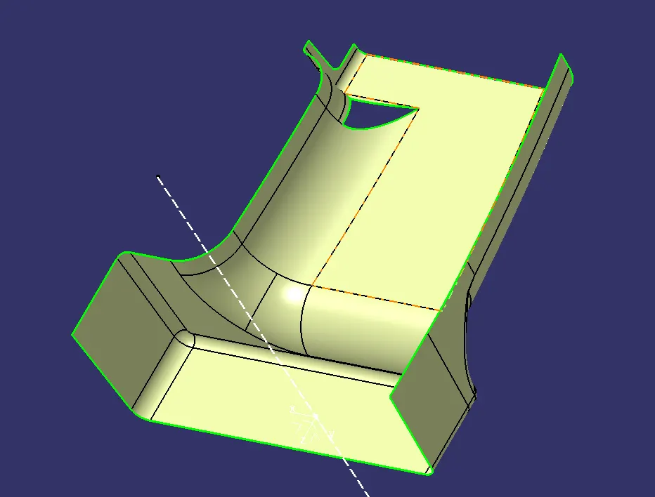
Fig 5. Offsetting class A surface and a part seems missing.
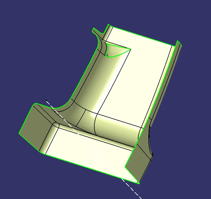
Fig 6.B surface cleared by multisection surface tool.
Class C Creation
The class C surface is created using sweep command from Class A surface boundary, and the draft angle with respect to the tooling axis is taken as 3º for edges which are perpendicular to the tooling axis and 90° with respect to the suface for edges that are parallel to the tooling axis. The bounday cannot be taken in a single stretch. It is extracted as multiple sections using multiple extact and sweep command is used. Then after the neessary trims, Class A is joined with Class C and later trimmed with Class B surface to form tha final trim.
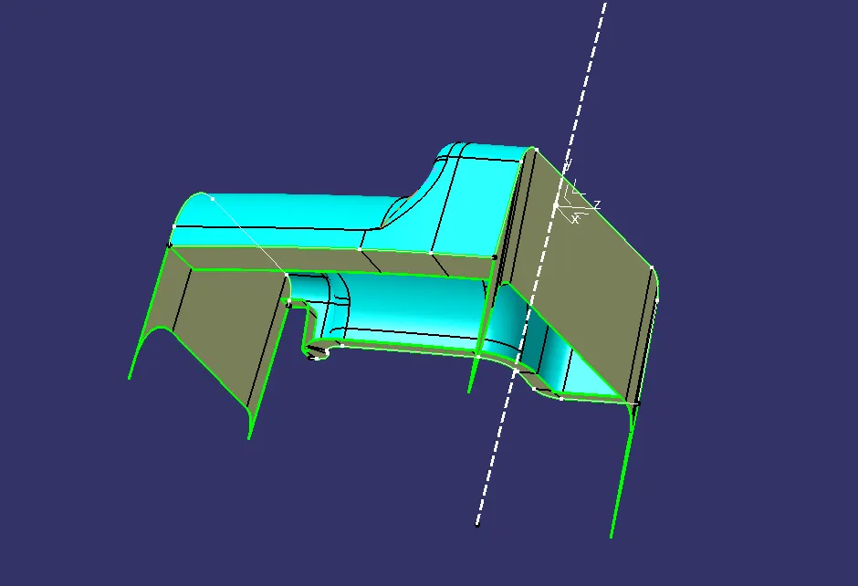
Fig 7. surface formed from class A usung sweep tool.
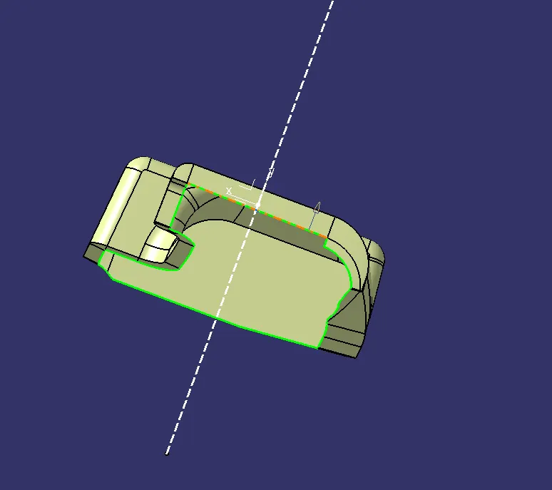
Fig 8. class surface A and C surface joined.
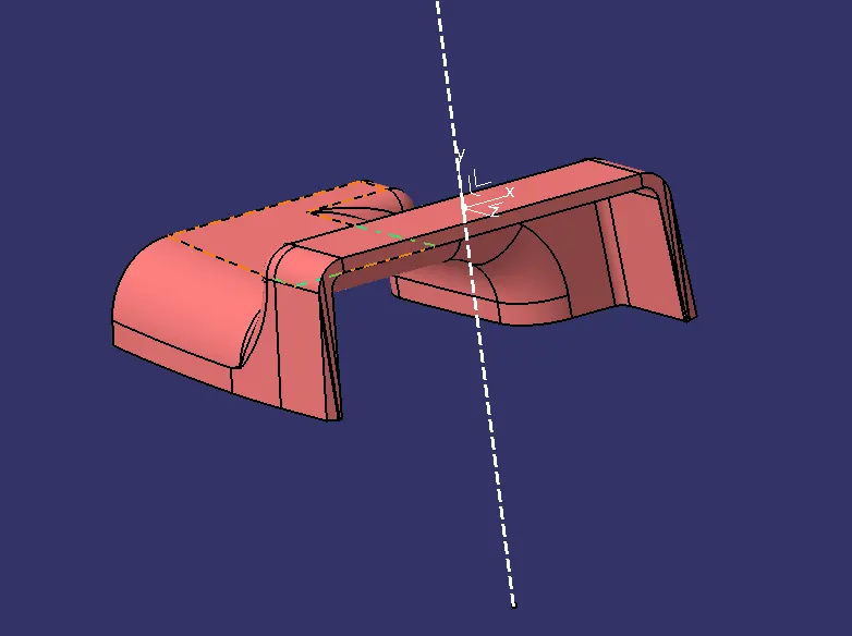
Fig 9. Final surface formed by trimming with B surface.
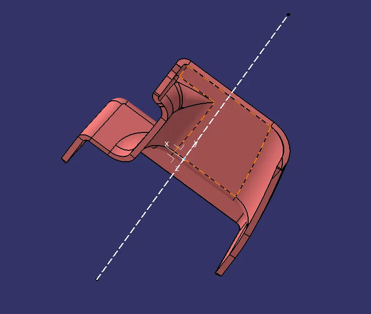 .
Fig 10. Final surface formed by trimming with B surface
Rib Creation on the part
Ribs provide stiffness and strength to the component economically without increasing the overall wall thickness. They also provides following needs such as
- Locating and arresting components in an assembly
- Providing alignment in mating parts
- Acting as stops or guides for a mechanism
Design Rules for Ribs are given below
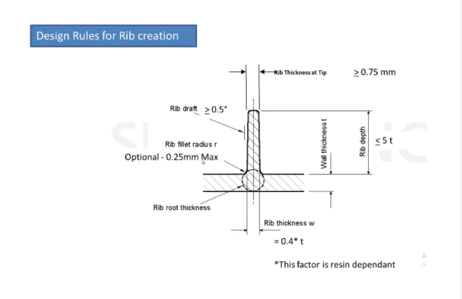
Fig11. Conditions for rib design.
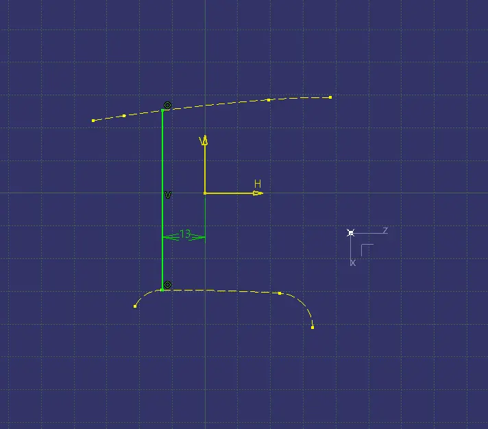
Fig12. Rib 1 sketch .
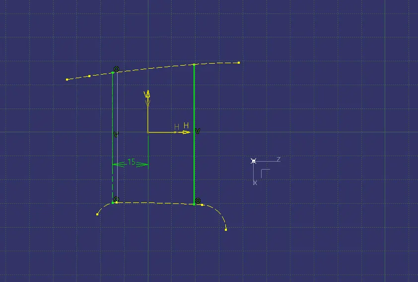
Fig13. Rib 2 sketch .
The following process is followed for rib creation
- The flat face on which the rib is need is extracted and the sketch of the rib is drawn.
- The rib is then thickened to 1.2mm which is the 0.4 times the thickness of base.
- The draft of 0.5 degree is given to the thickened part.
- Union trim is done for the rib to the part body and fillets of 0.25mm is given ,the same process is also given to rib 2.
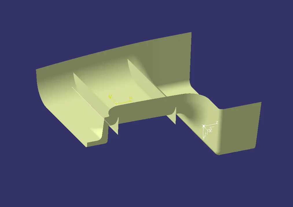
Fig14. Ribs are sketch is extruded .
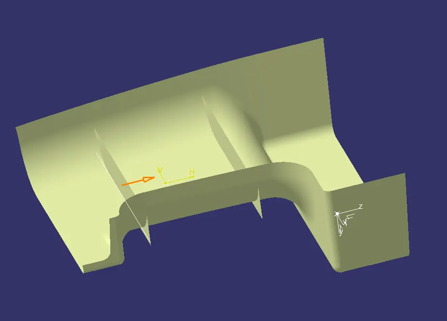
Fig15 Rib 1 is thickened .
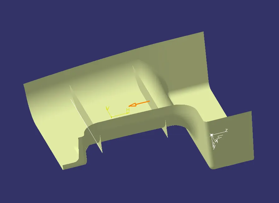
Fig16 Rib 2 is thickened .
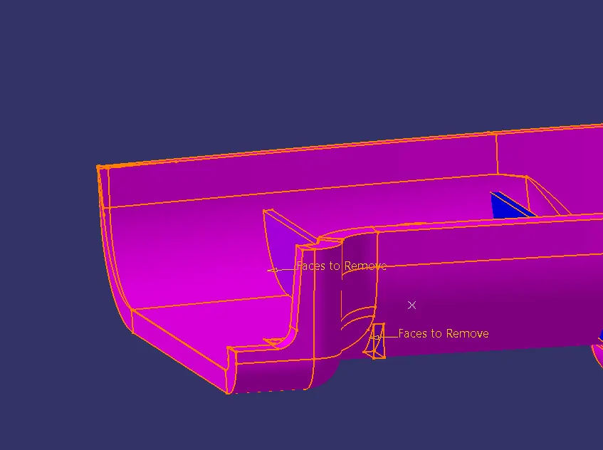
Fig17 Rib 1 is union trimmed
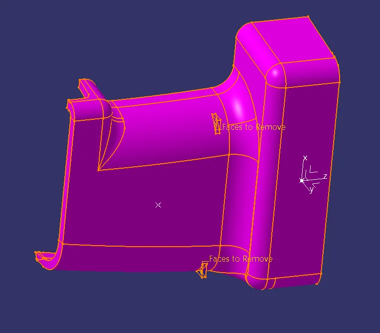 .
Fig18 Rib 2 is union trimmed
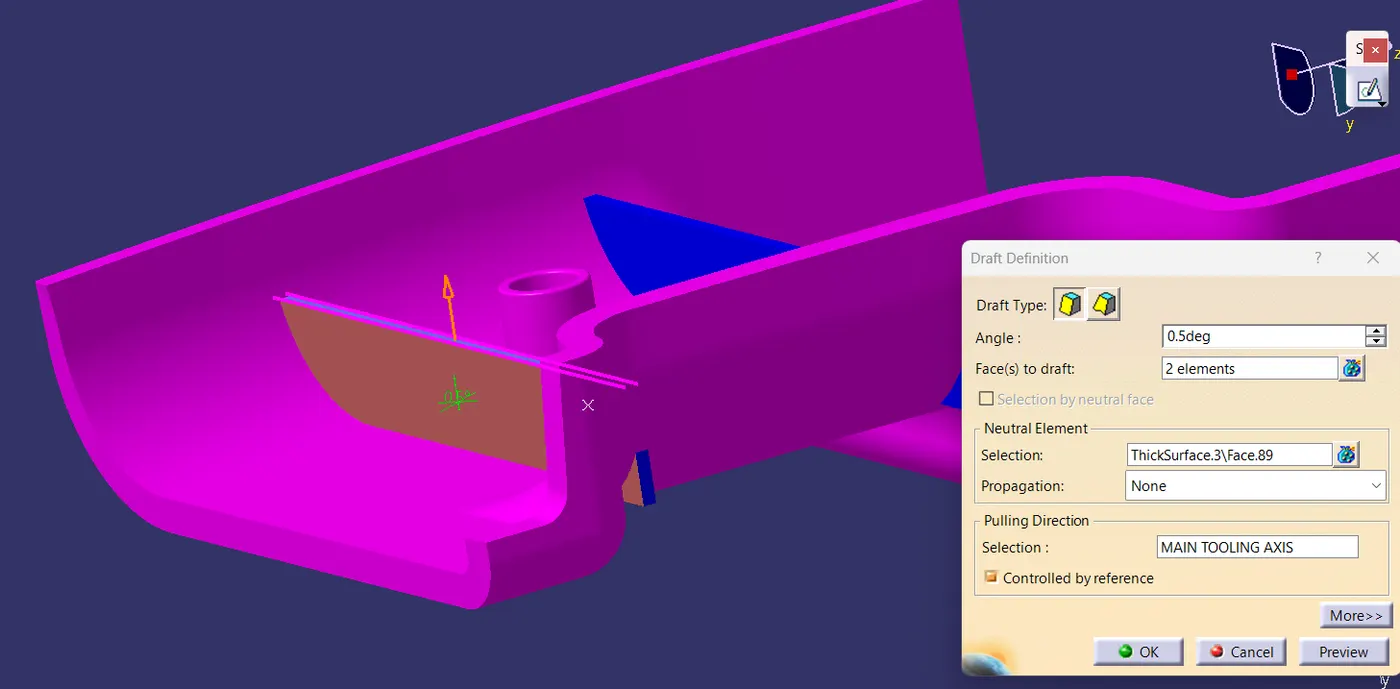
Fig19 Ribs are given draft angle.
The rib root thickness is also measured by taking an intersect between YZ plane and part body. A tritangent circle is constructed at the base of the rib and its thickness was measured and the variation with the base thickness was well within 30%.
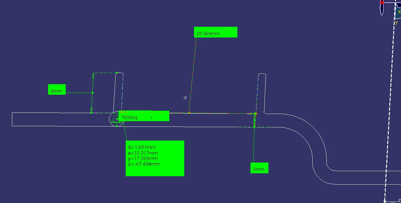
Fig 20. Rib root thickness measurement.
The measurements are checked whether they satisfy the rules of designing the ribs.
Screw Boss Creation
Bosses are projections designed to accept inserts, self-tapping screws etc. for use in mounting, fixing or fastening or assembling parts.
Design Rules for screw bossare given below,
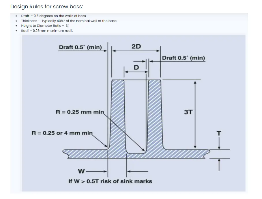
Fig 21. Conditions for screw boss design.
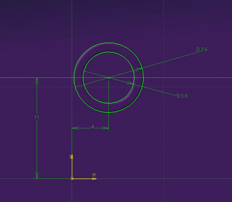
Fig 22. Sketch for screw boss creation.
Steps followed for screw boss creation screw
- The sketch for screw bosses are also done on the same reference plane as used for ribs.
- The diameter here is used for M6 screw diameter of 5.6.
- The thickness of the 1.2 on both sides so 7.6 mm.
- The screw boss is padded to a height of 8mm which is less than 3t.
- Drafts are given to the screw bosses for 0.5 degree.
- The screw bosses are added to the part body.
- Fillets of minimum 0.25 are provided.
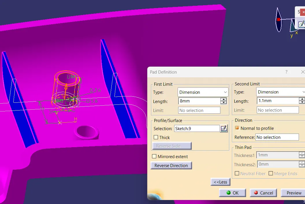
Fig 22. Pad operation for screw boss sketch
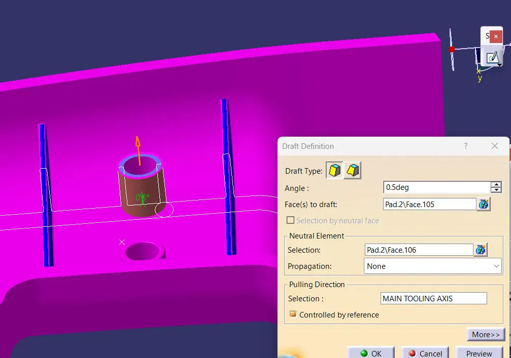
Fig 23. Draft for outer wall.
DIFFERENT VIEWS OF THE PART
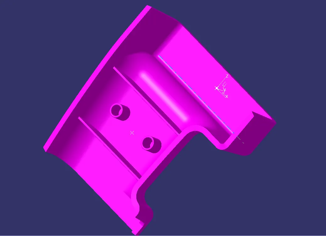
Fig 24. Isometeric view of the part.
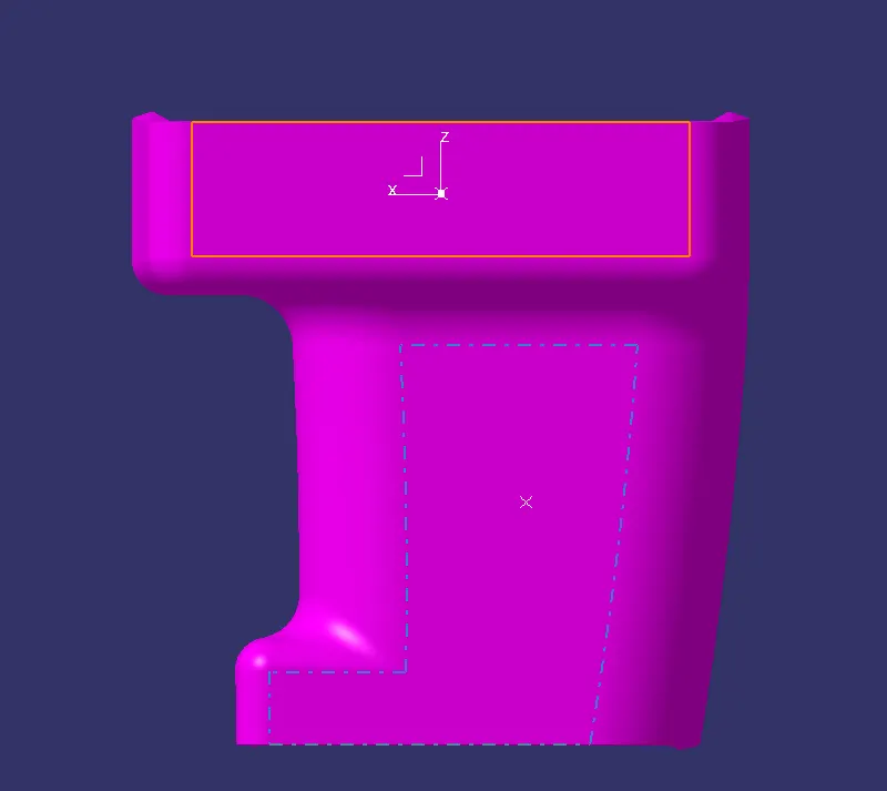
Fig 25. Top view.
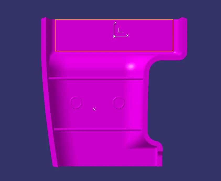
Fig 26. Bottom view.
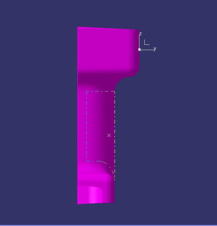
Fig 27. Side view.
DRAFT ANALYSIS
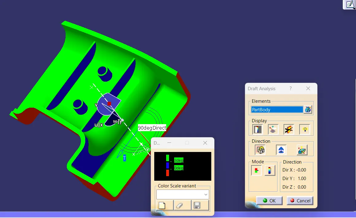
Fig 28. Draft analysis .
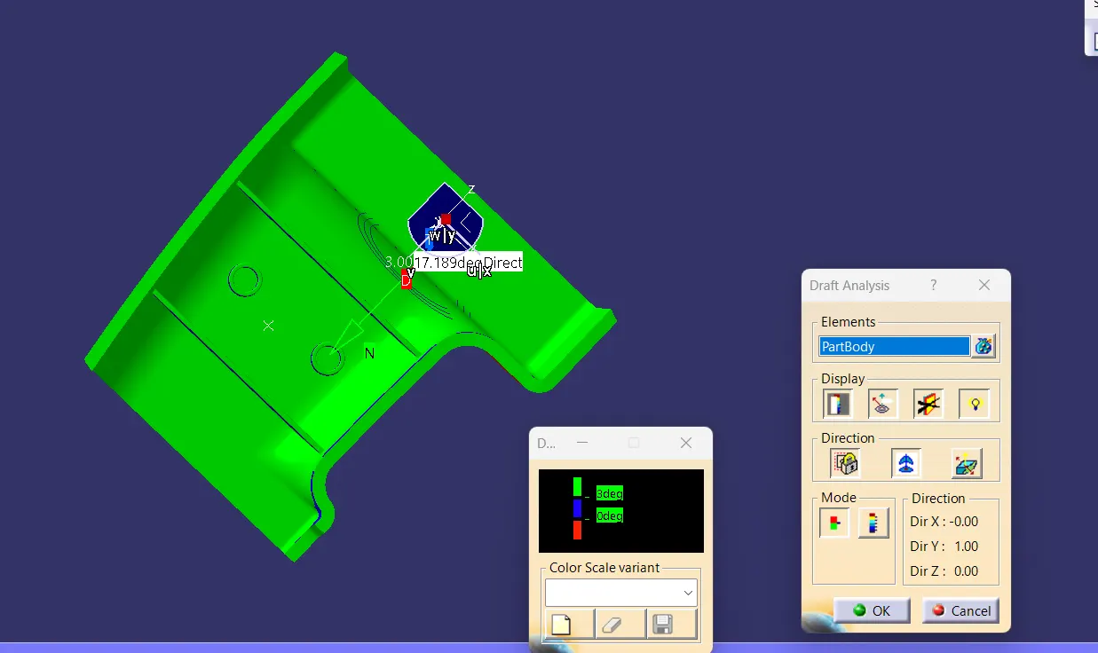
Fig 29. Draft analysis
Steps in draft analysis are given below
- The part view is customised to material view
- The draft analysis tool is selected and compass is aligned along the tooling axis.
- The compass is locked and the part is selected to perforn the analysis.
- The region fullfilling the draft are given different colo