Week 11 - Final project
Final project – Door Trim Panel
AIM
Development of a Door Trim panel CAD model considering following inputs as like in OEM and tier1 companies
OBJECTIVE
- Create tooling axis for the given CLASS-A surfaces.
- Create CLASS B and C surfaces using the given CLASS-A surface.
- Create solid body part sing the close surface command in the part design workbench.
- Create the engineering features like heat stakes, flanges, push pins and dog house on the B side of the part.
- Perform draft analysis for CLASS-A surfaces and final plastic components.
INTRODUCTION
Door Trim
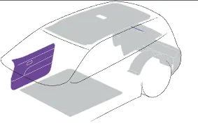
Door panels serve as an interface between the interior of the car and the inner workings of the door, and between vehicle occupants and the door. They are expected to meet a variety of design specifications regarding safety, aesthetics, and functionality.
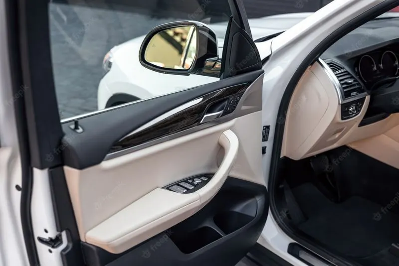
Door currently has an inner full width panel consisting of electronic windows, central locking system and speakers. These panels typically consist of a foamed core covered with either textiles or plastics.
CLASS-A SURFACE
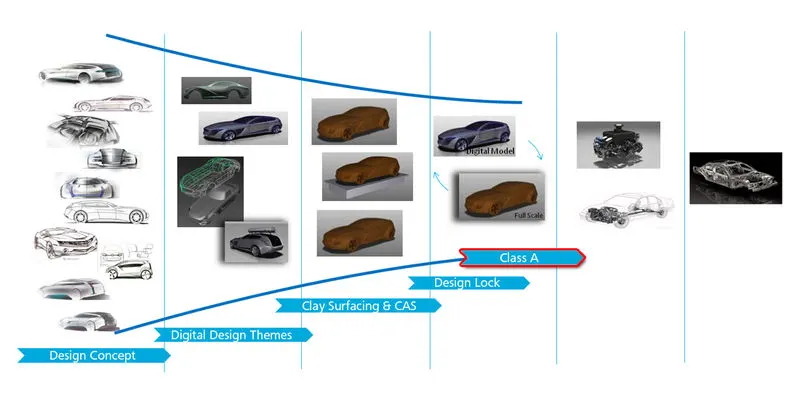
Class-A surface means visible surface. It gives the aesthetic of the component which is created by the styling team and gives to the part design engineer to create the part with all engineering aspects.
The Class-A modelling process typically starts with a fully developed design, either as a scanned clay model or an Alias model. Because the design isn't changing, the modeller has the time to build surfaces to the highest quality standards, ready for production.
The challenge for Class-A is to combine the need for:
- Aesthetic Quality - Continuity and Highlights
- Engineering Requirements - Flanges and Fit
- Production Requirements - Modelling Tolerances
CLASS-B SURFACE
Class-B surface means thickness of a part it is not visible and is inside part. In other words, Class-B surface is a surface below a certain thickness from the class-A surface. This is the surface that contains engineering aspects of a model.
The Class B finish is a quality finish with only minimal imperfections. A Class B finish is the most common finish for exterior surfaces. It is normally specified on surfaces such as external covers, panels, and parts that are fairly prominent.
CLASS-C SURFACE
Surface that joins class-A and class-B surfaces is class-C surface. Class C is often specified for interior surfaces not readily visible, surfaces that will be covered by another part when assembled
Automotive plastic components
Plastic has become one of the key materials required for the structure, performance, and safety of automobiles in recent years, with growth in plastic consumption being driven by light weighting trends for fuel efficiency and consequently lower greenhouse gas emissions. The high absorption properties of plastics also allow the vehicle to meet stricter safety standards, while the use of engineering plastics allows for minimization of the mass of parts used in vehicles as they offer more design freedom compared to metals.
High automotive performance demands parts that handle it all. Plastics perform from the engine to the chassis; throughout the interior to the exterior. Today’s automotive plastics make up approximately 50% of the volume of a new light vehicle but less than 10% of its weight.
Currently, there are about 30,000 parts in a vehicle, out of which 1/3 are made of plastic. In total, about 39 different types of basic plastics and polymers are used to make an automobile. More than 70% of the plastic used in automobiles comes from four polymers:
- Polypropylene,
- Polyurethane,
- Polyamides and
- PVC
Trim applications require a variety of essential plastic material properties:
- High-quality aesthetics and haptics
- Reliable stability and long-term durability
- Ability to withstand UV light and exposure to high temperatures
- For load-bearing trim parts: enhanced stiffness retention at elevated temperatures and high dimensional stability
- Tight fit if assembled with other interior components/materials
- Impact resistance and good ductile performance at low temperatures, especially with safety-related components (airbags, passenger restraint systems)
INPUT SURFACE
INPUT MASTER SECTION
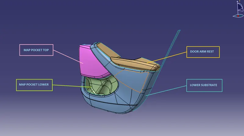
Master sections are the guides for design requirements which decide the component packaging after technical (Styling, Concept or Class-A) surfaces.
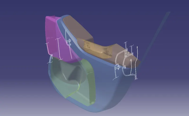
Design Methodology
Software used – CATIA V5
Sequential design procedure
CLASS-A surface Quality Check
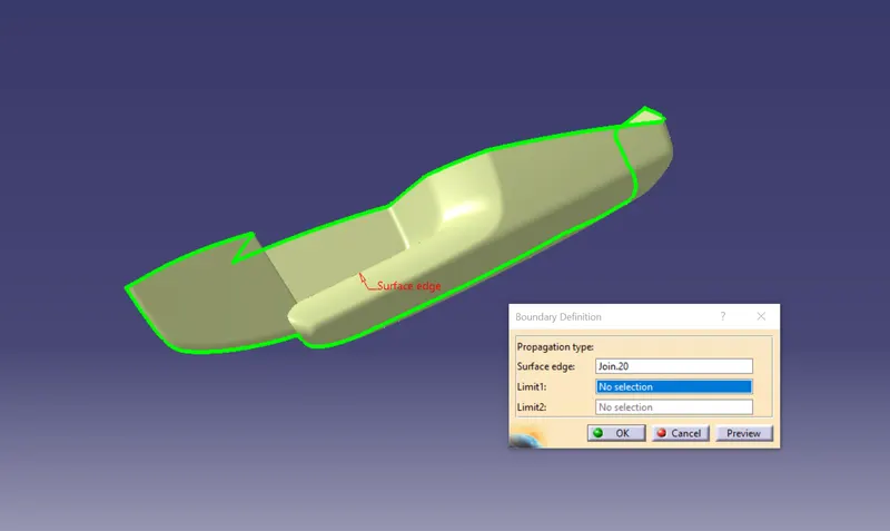
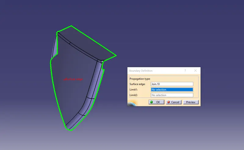
- Before starting designing we need ensure the quality of the given surface using the Join or Boundary commands.
- Lower substrate
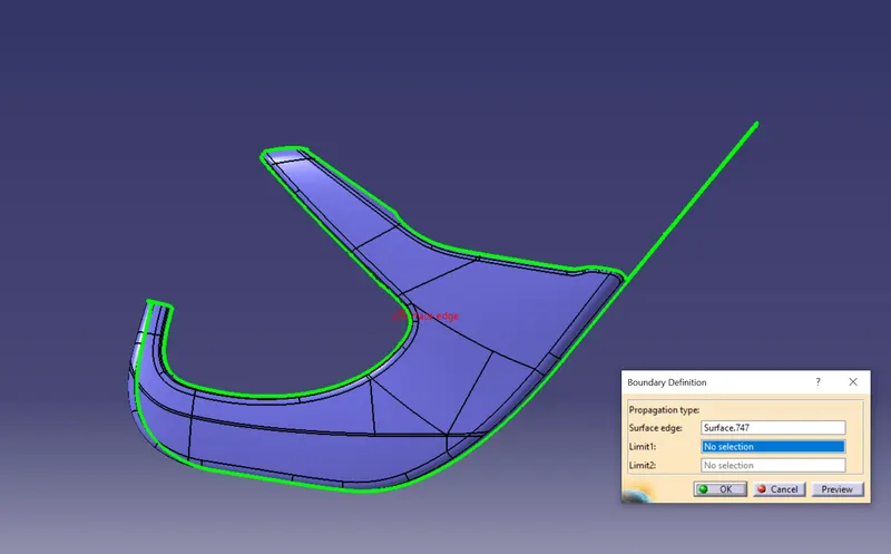
- Map pocket lower
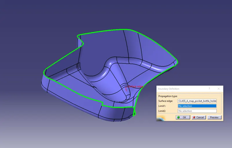
- Map pocket upper
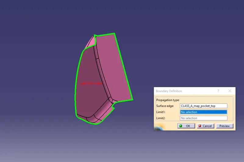
- Door arm rest
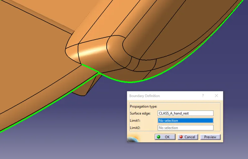
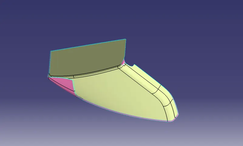
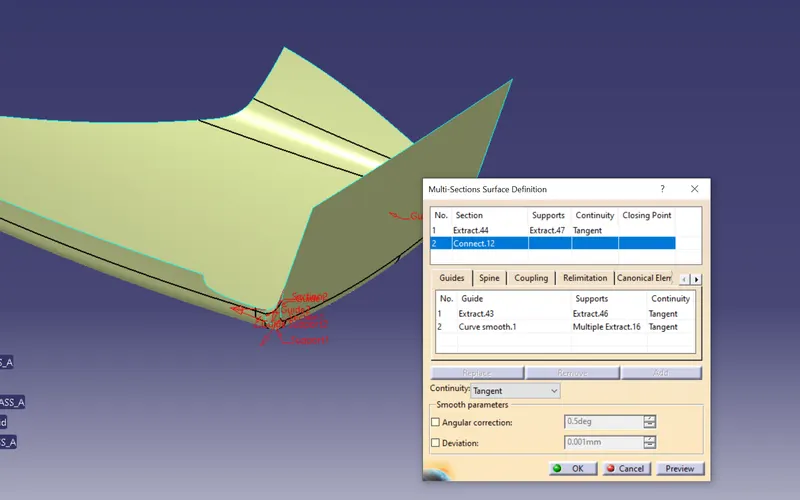
- Patch has been detected during the quality check and improved the class A surface using multi section surface command.
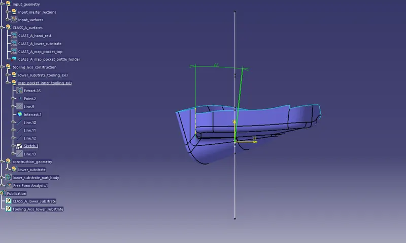
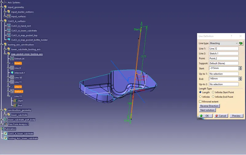
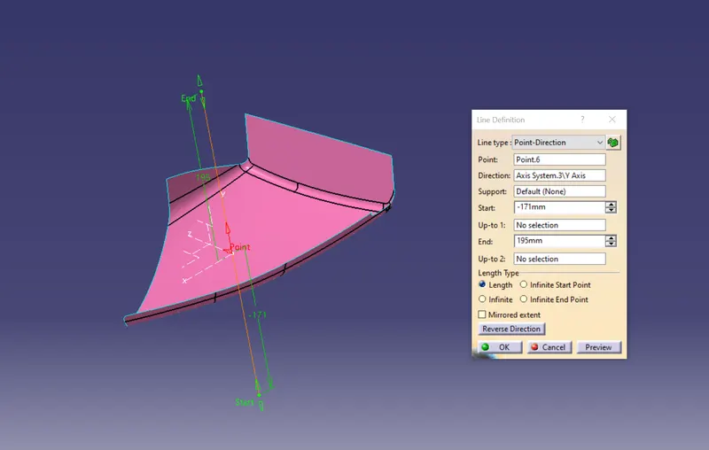
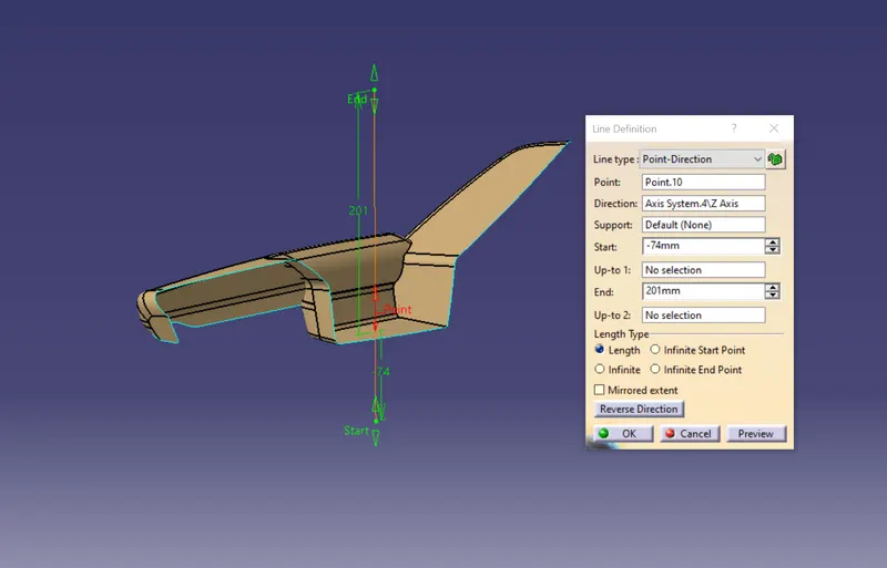
Tooling Axis Creation
Tooling axis represents the opening and closing of the mold core and cavity during the manufacturing of the components.
- Lower substrate
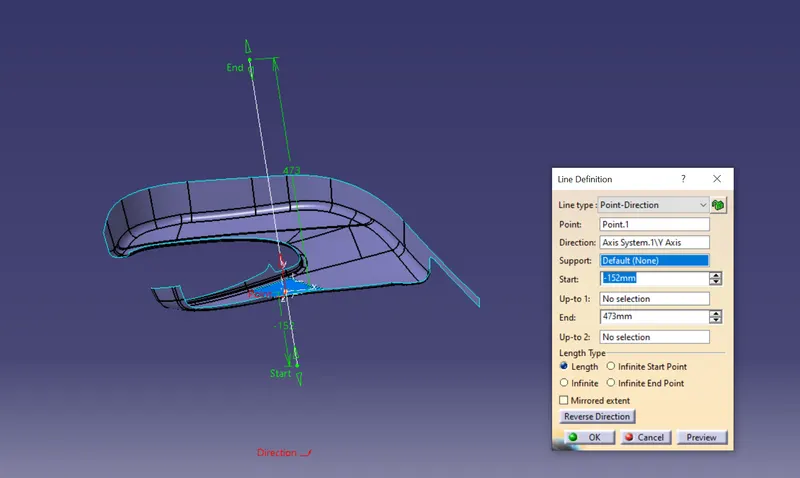
- Map pocket lower
Here intersection method is used for creating the tooling axis.
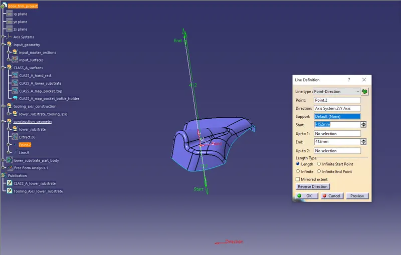
- Map pocket upper
- Door trim arm rest
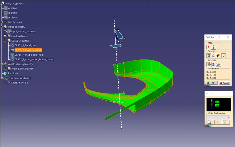
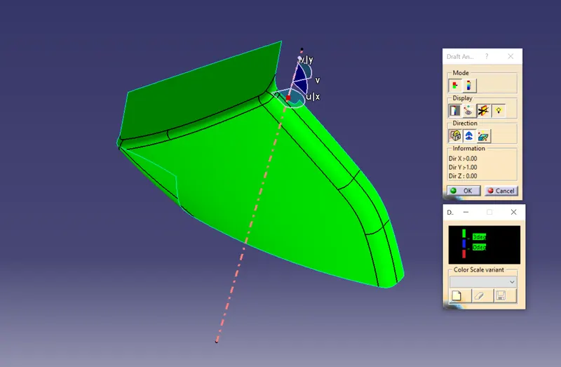
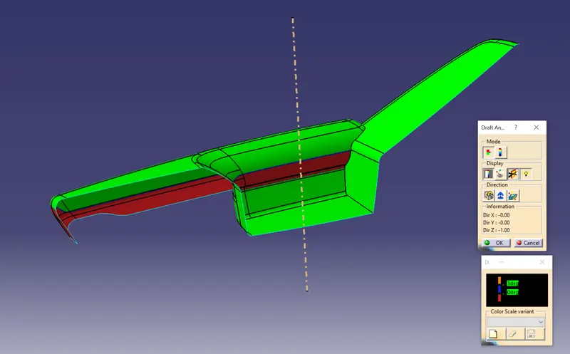
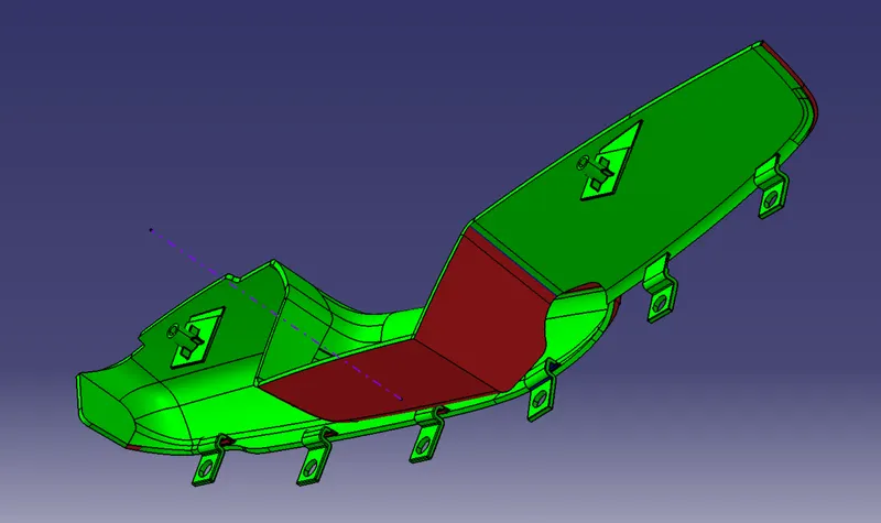
Perform draft analysis on given CLASS-A surfaces
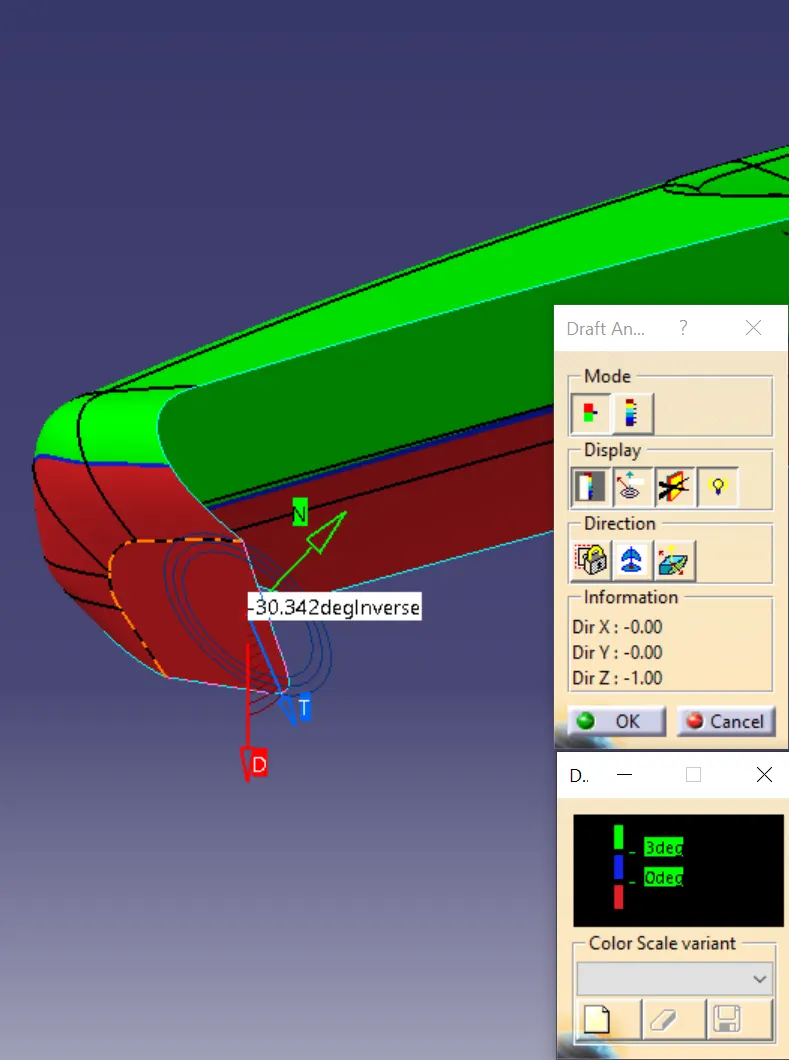
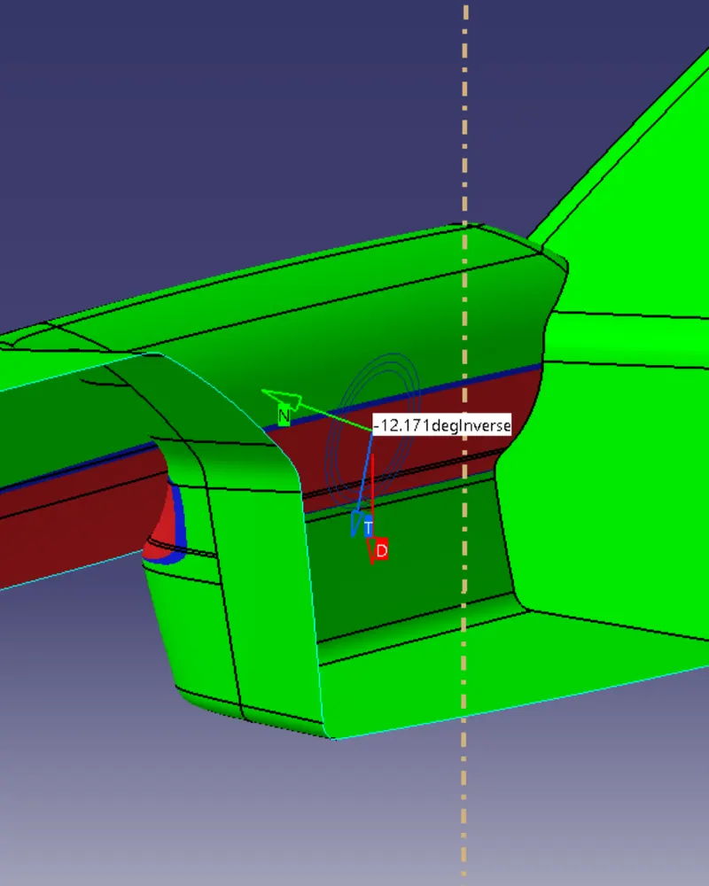
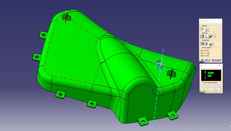
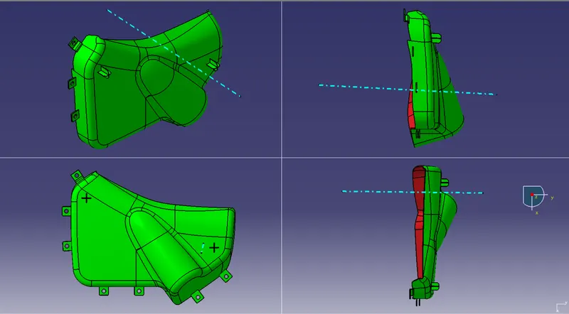
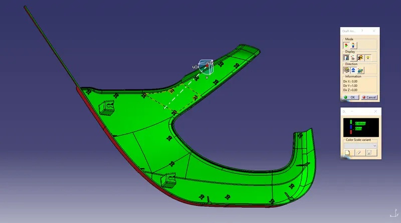
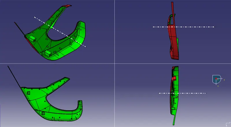
The Draft Analysis is a command enables you to detect if the part you drafted will be easily removed. This type of analysis is performed based on colour ranges identifying zones on the analysed element where the deviation from the draft direction at any point, corresponds to specified values.
As we know for injection molding the draft on the surface should be positive and greater or equal to 3 degrees. Areas with the draft less than 3 degrees are a bit difficult and costly to manufacture.
Procedure for performing the draft analysis are as follows
- Change the view mode of the component to be in customized parameter mode and then select the shading mode as materials.
- Then open the featured draft analysis tool from the insert menu.
- Then click on use the compass to define the current drafting direction and then drag and align the compass on the Tooling axis.
- Then lock the draft direction and perform draft analysis by clicking on the component.
- The green colour shows the positive daft tooling direction and the given surface passes the draft analysis.
- Click on the analyses under the running point to check the draft analysis on the individual faces. It shows how much draft on specific points when we move the cursor point.
- Colour representation
GREEN - positive draft (more than 3 degree)
BLUE - draft 0 to 3 degrees
RED - Negative Draft
- Lower substrate
- Map pocket lower
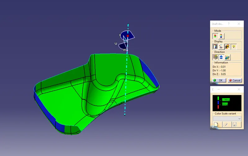
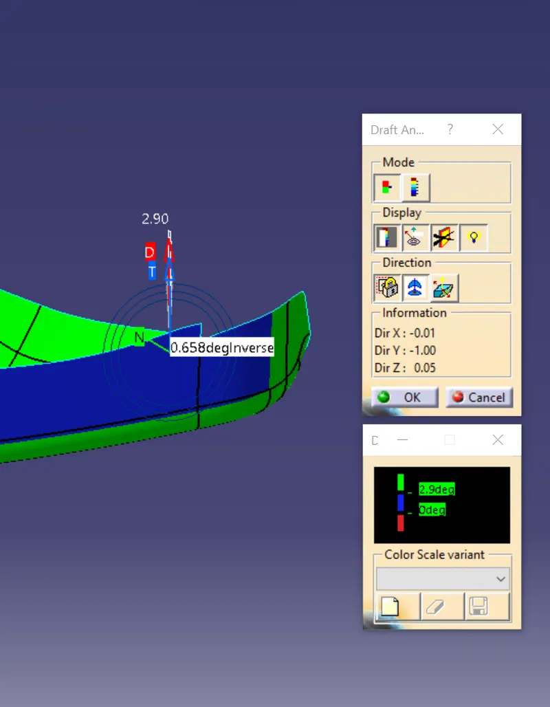
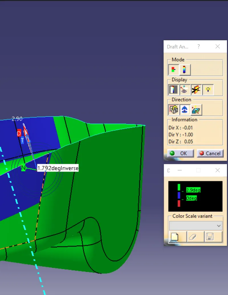
- Map pocket upper
- Arm rest
CLASS-B SURFACE creation
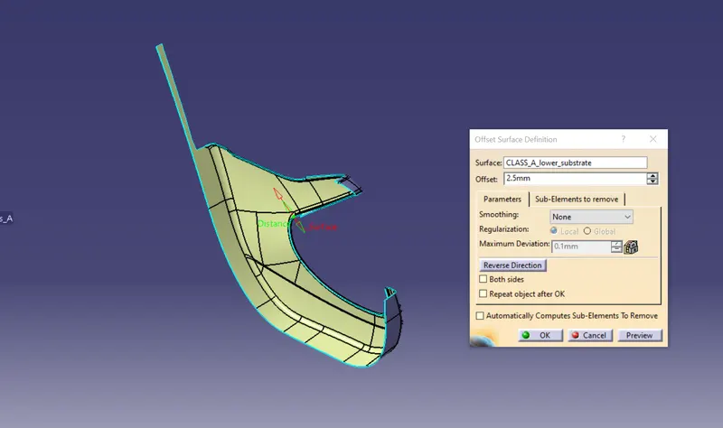
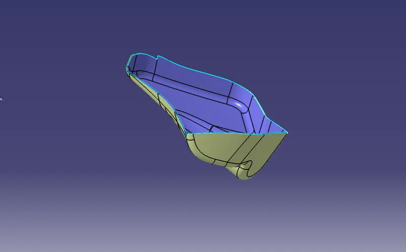
- Creating class B surface by offsetting class A surface about 2.5mm as per master section.
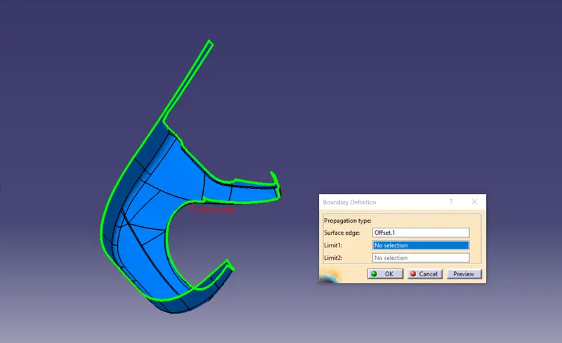
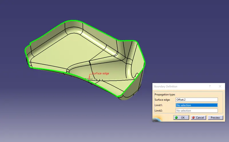
- Check for the discontinuity and patches.
- Use multi section surface and sweep commands for any patch’s reworks.
- Lower substrate
- Map pocket lower
- Map pocket upper
Patch rework on the offset surface
- Arm rest
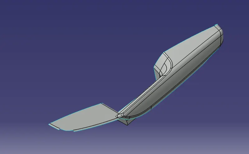
Class-B surface after reworking on the patches
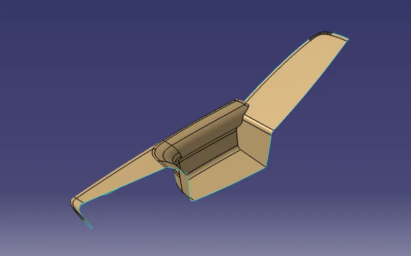
CLASS C SURFACE creation
- Creating Class-C surface using sweep and multi section surface commands.
- Lower substrate
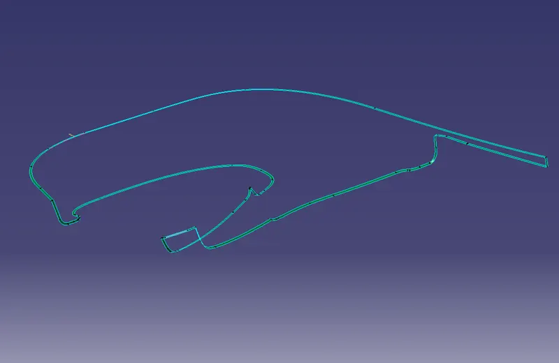
- Map pocket lower
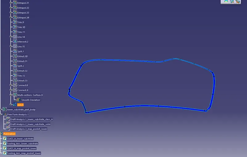
- Map pocket upper
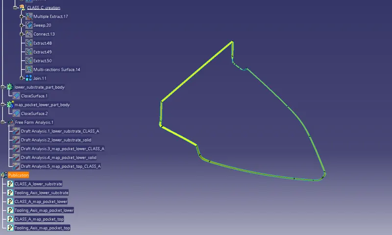
- Arm rest
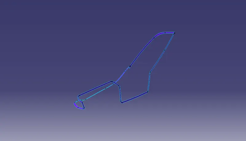
FINAL SURFACE creation
- For creating the Finals door trim surface, join the CLASS-A and CLASS-C surface together.
- Then Extrapolate the B surface little bit outward direction to make sure that there would not be any gap when trimming with joined surface.
- Then Join the extrapolated CLASS-B surface with Join surface (CLASS-A and CLASS-C)
- Lower substrate
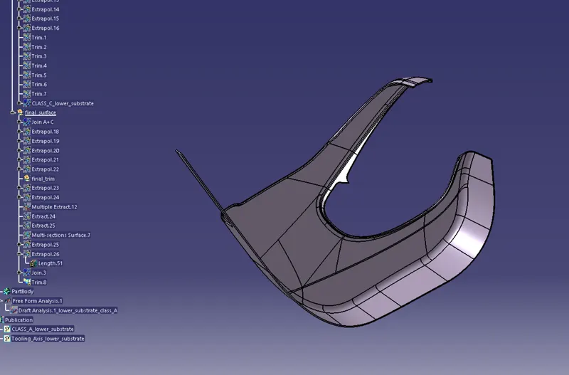
- Map pocket lower
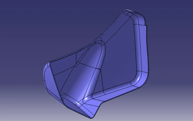
- Map pocket upper
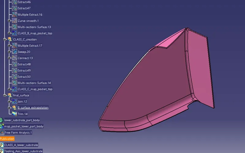
- Arm rest
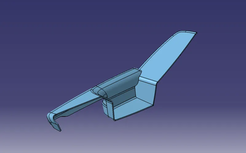
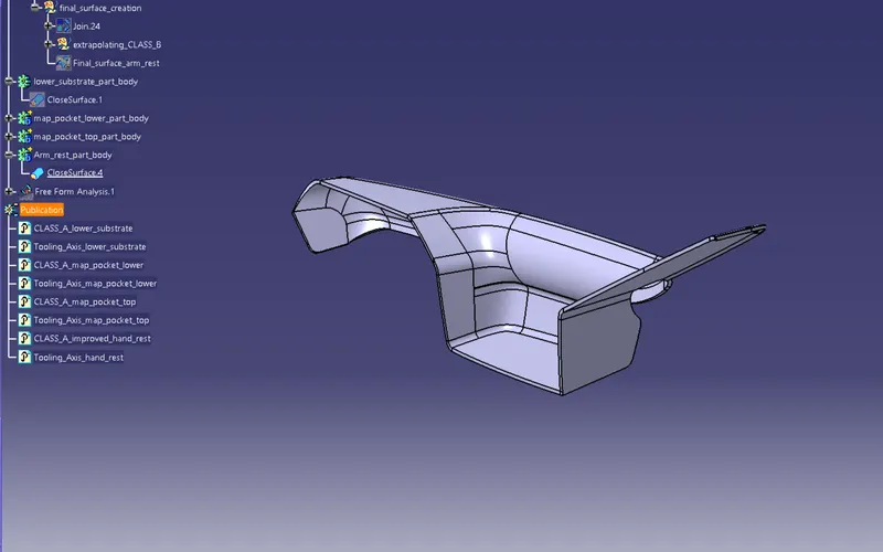
Make a solid part body using the close surface command in the part design workbench
- Lower substrate
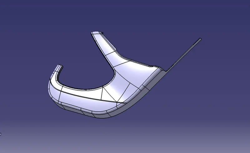
- Map pocket lower
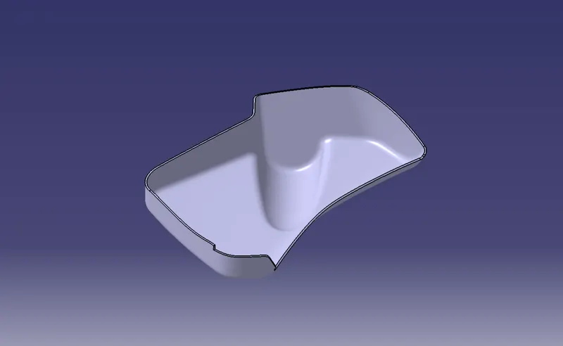
- Map pocket upper
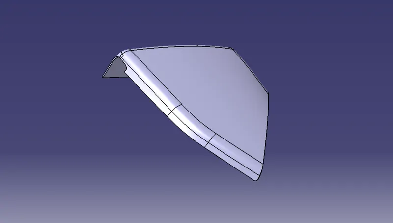
- Arm rest
ENGINEERING FEATURES creation
- HEAT STAKING
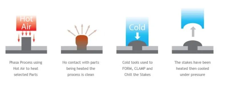
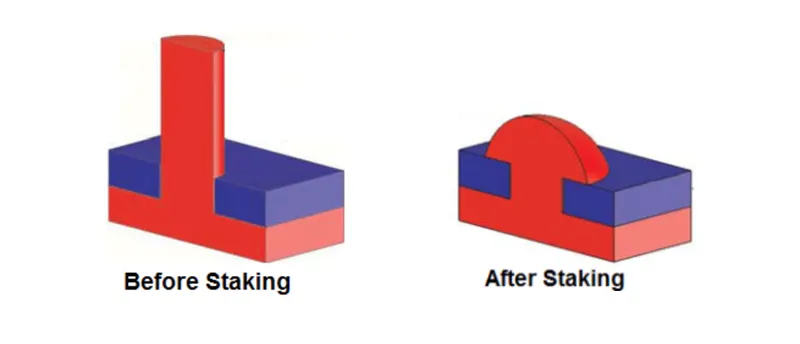
Heat staking also known as thermoplastic staking is the process of joining two dissimilar materials together. In heat staking we use local heating and cooling to raise the temperature of plastic components and allow plastic reforming to be carried out. This reforming can be used in a wide variety of applications.
Heat staking can be performed using wide range of thermoplastic materials including polypropylene, ABS, polycarbonate and many others. The integrity of a thermal staked assembly depends greatly upon the geometric relationship between the boss and the thermal tip.
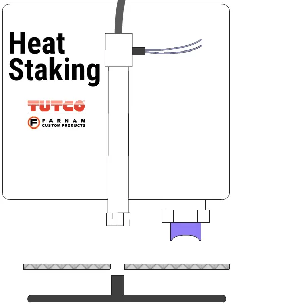
The heat staking tip is brought into contact with the thermoplastic part to be reformed. The heating tip is then heated by direct electrical heating within the tip for a short period of time. The heated tip softens the plastic material and forms the melted plastic into the shape of the tip.
Heat Staking Benefits:
- Similar and dissimilar materials may be joined: metal to metal, plastic to plastic, metal to plastic
- Accurate control operating within a small process window
- Local heating resulting in no damage to surrounding materials
- Processing of glass-filled materials
- No mechanical vibration
- Many heat-stake shapes are possible through custom designed tools.
General guide lines for bosses
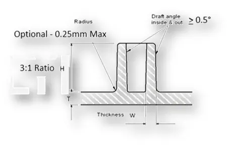
- Draft – 0.5 degrees on walls of boss
- Thickness – Typically 40% of the nominal wall thickness at base.
- Height to diameter ratio – 3:1
- Radii – 0.25mm maximum radii.
- Boss gussets must meet rib guidelines
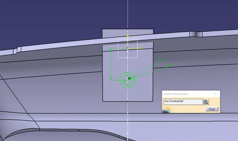
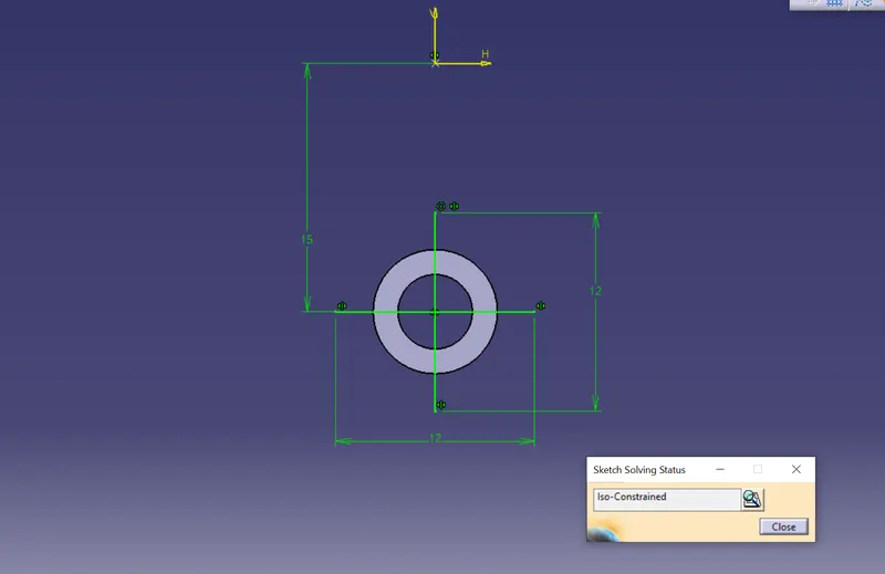
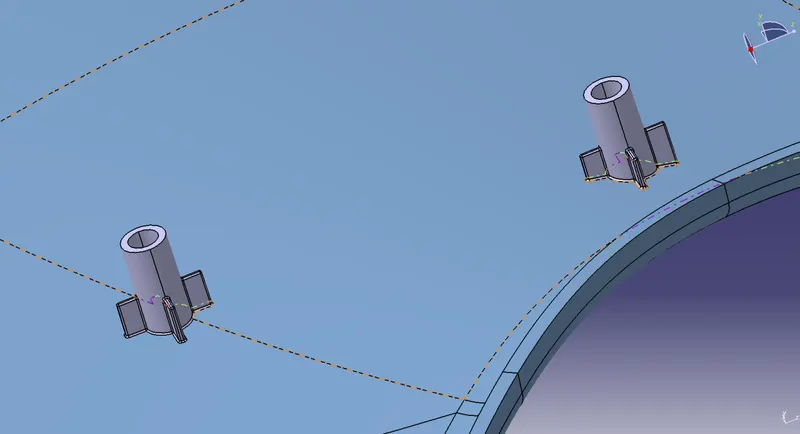
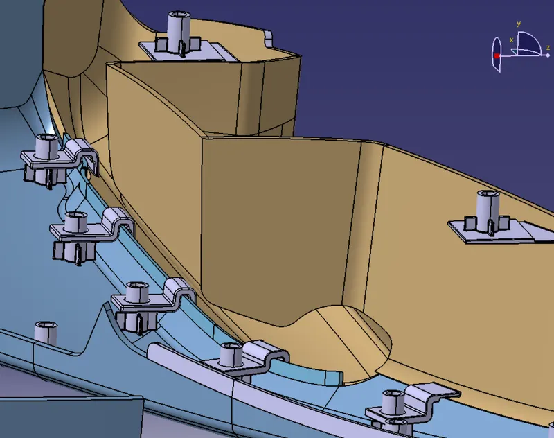
- COUNTER PART/MOUNTING FLANGES FOR HEAT STAKES
These are the flanges that’s going to mate with heat stakes to make a joint between two plastic components.
Referred master section for creating the heat stake counter flange.
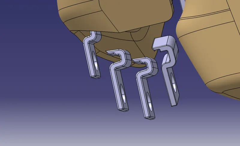
0.5 mm counter part clearance have been given for heat stake entry.
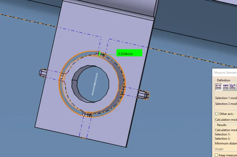
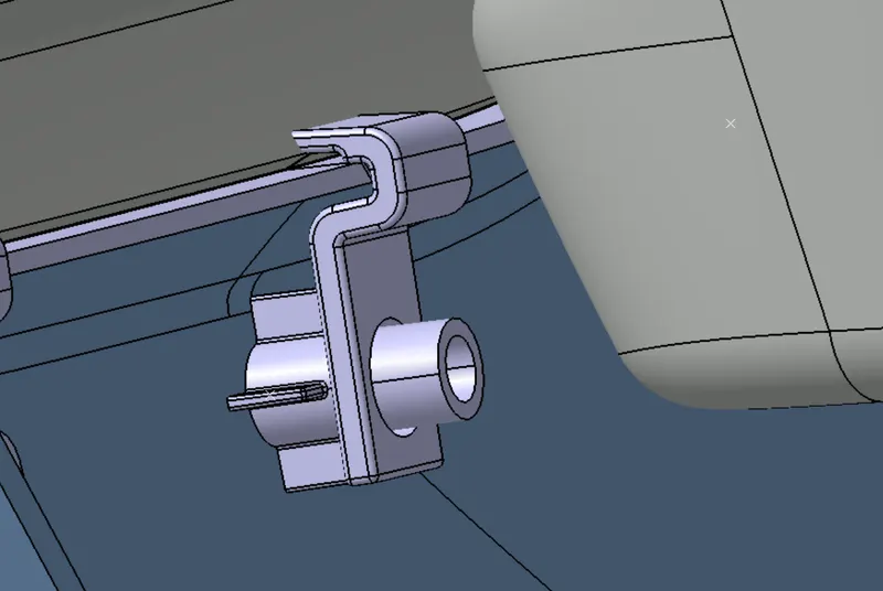
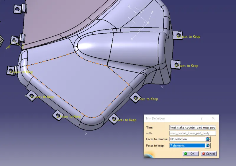
Counter Flanges are attached to the plastic components using Boolean operations
- DOG HOUSE
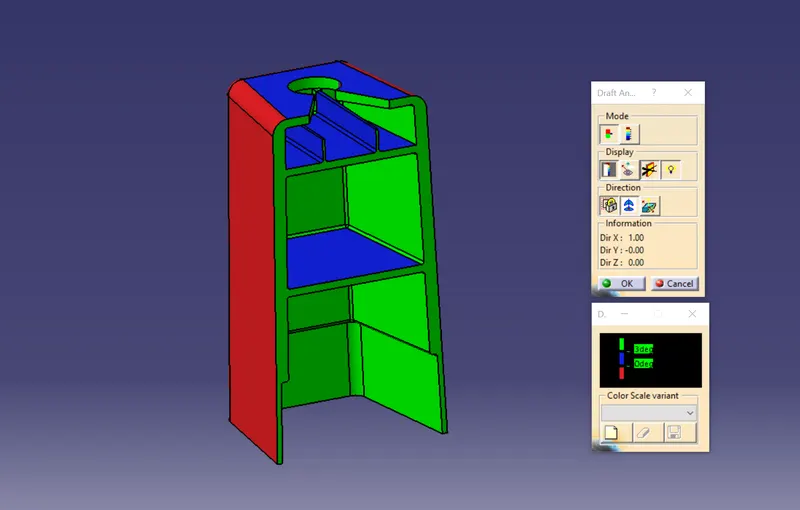
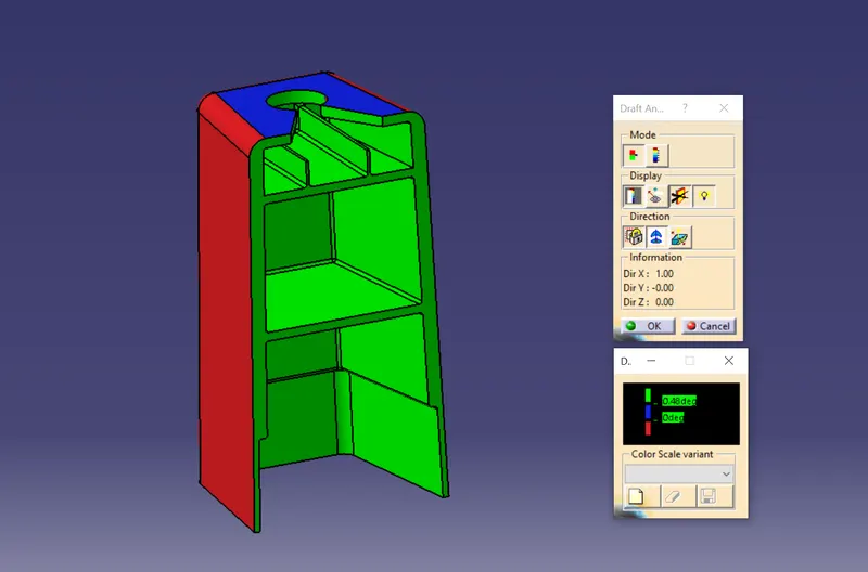
Dog house is an engineering feature used in plastic trim design. Dog houses are used as supporting features. Sometimes other engineering features like snaps; locators etc. are mounted on them to increase their strength. Dog houses are subjected to draft analysis to prevent breakage of the component during ejection from mould cavity. Dog house and other engineering components are built on a B-surface.
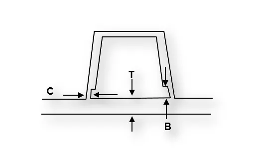
Dog house design guid lines
- Dog house wall thickness at intersection of part wall ( C ) should be 40% or less than main wall thickness ( T ) to avoid sink marts on the part A surface.
- Height of ( B ) should be between 3 to 6 mm.
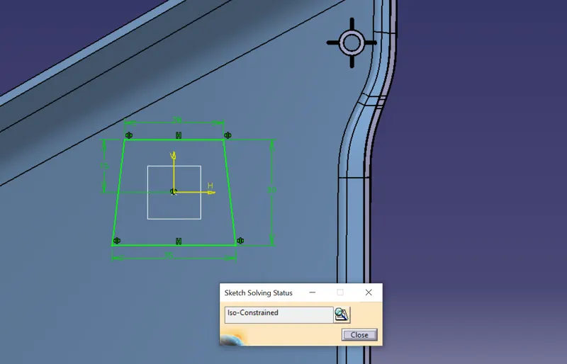
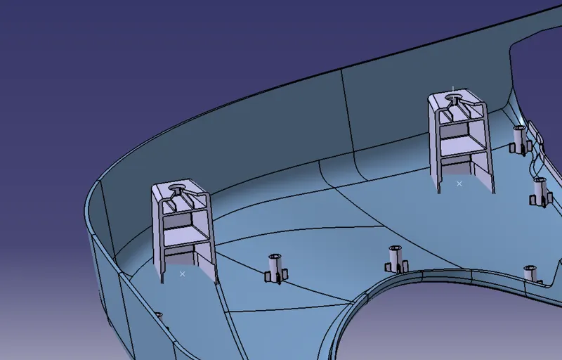
Side core Axis
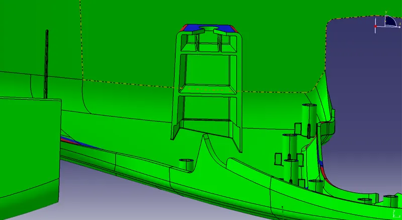
Since the dog house's inner walls will not be cleared in the main tooling direction, we need to create the tooling axis for the side core. A min of 0.5 degrees draft is provided on all the walls.
- Draft analysis of dog house using side core axis
- LOCATORS
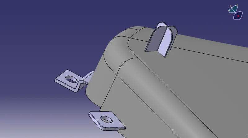
Locating pins are the rib like structures on the B surface which are used to position the child part with parent part while assembling and also helps to arrest the degrees of freedom of the part.
Design guidelines of ribs should be followed during the locator designing process.
- PUSH PINS
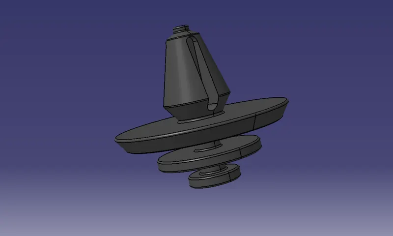
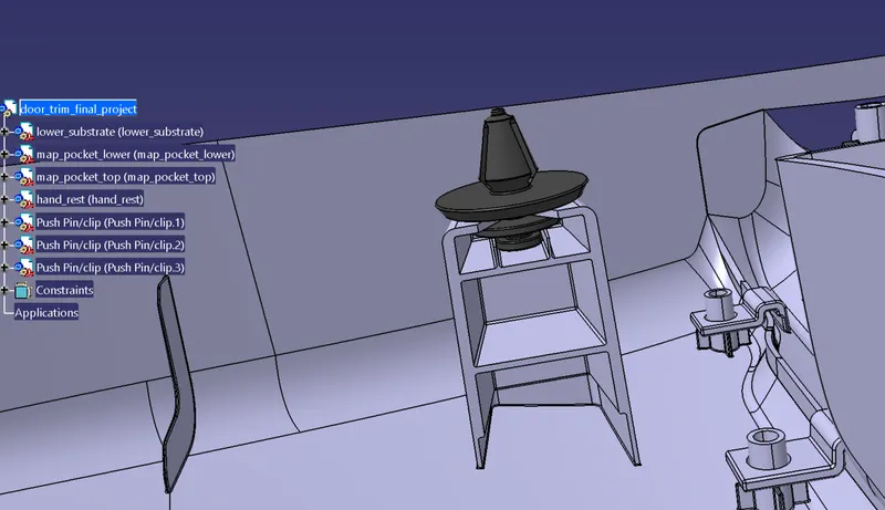
Push clips are used to attach plastic trims with the sheet metal components
- RIBS
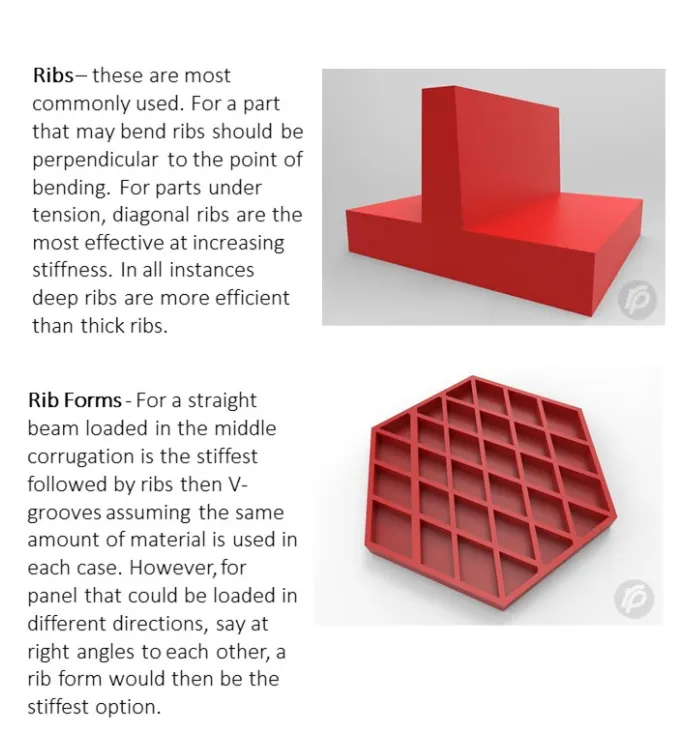
Ribs are a feature in plastic injection molded parts. They are thin extensions that run perpendicular from a wall or plane. They are commonly used to provide additional support and strength to a part. Thickness and location are essential to rib design.
Rules and regulations for create the ribs:
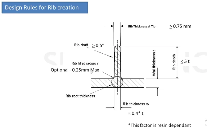
- Thickness of the rib t*0.4
- Height of the rib t*5
- Optimal radius 0.25mm
- Thickness on the top is greater than 0.75mm
- optimal draft angle for the faces is 0.5 degree
- For spacing for steel 3:1 and preferred 2:1
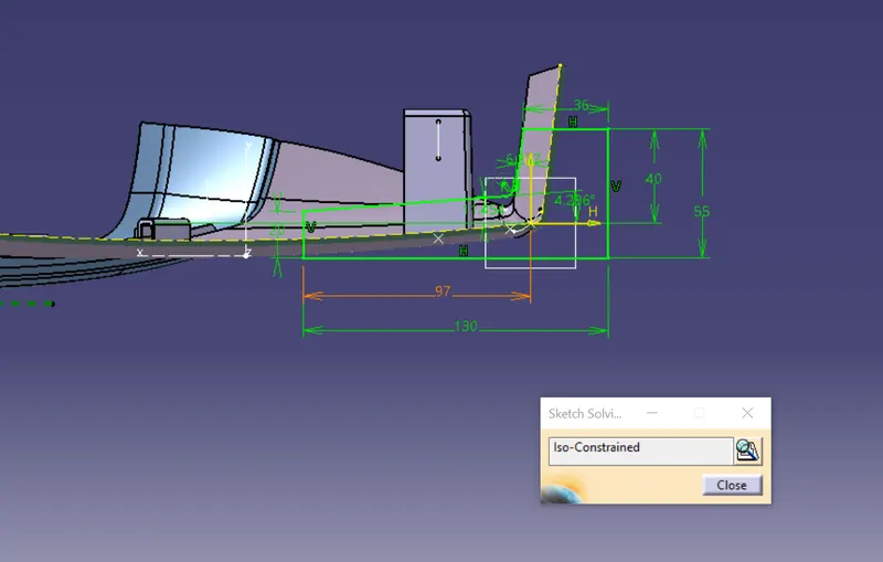
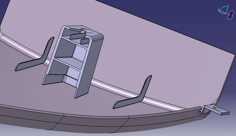
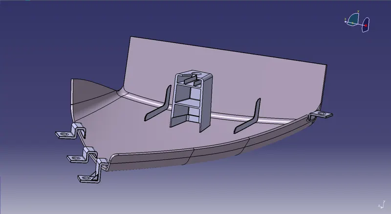
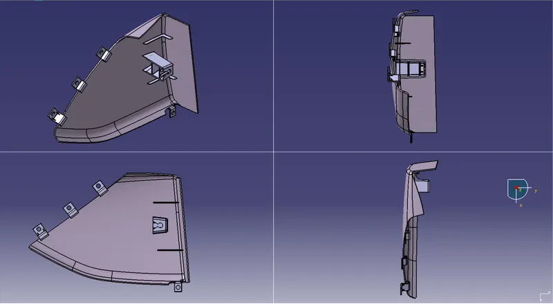
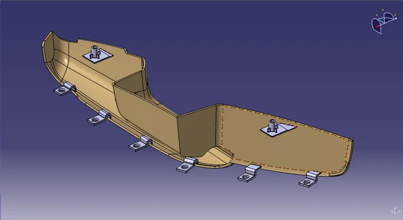
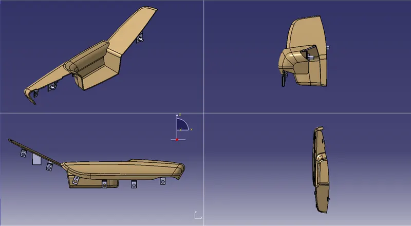
FINAL COMPONENTS WIH ALL THE ENGINEERING FEATURES ATTACHED
- Lower substrate
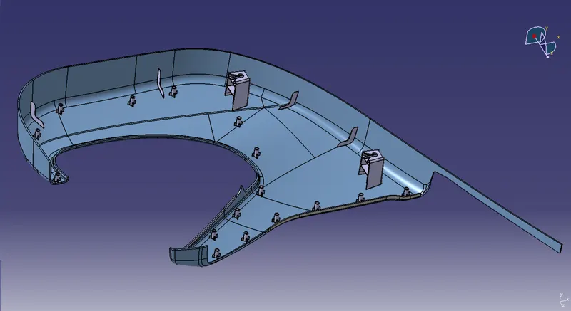
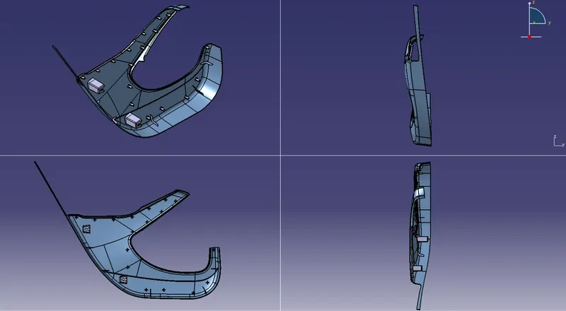
- Map pocket lower
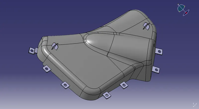
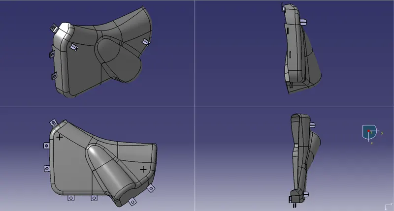
- Map pocket upper
- Arm rest
DRAFT ANALYSIS OF FINAL COMPONENTS
Draft angle is given 0.48 degrees considering the engineering features minimum draft angle
- Lower substrate
- Map pocket lower
- Using side core axis for dog house attachment
- Map pocket upper
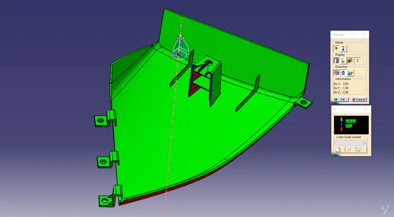
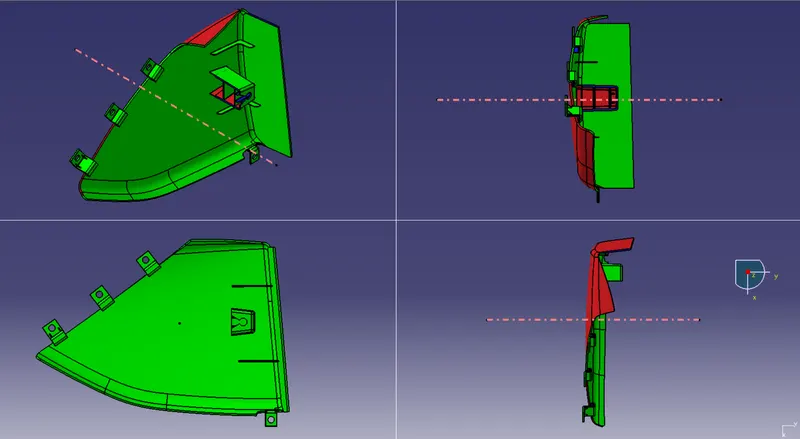
- Using side core axis for dog house attachment
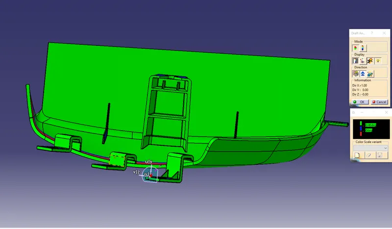
- Arm rest
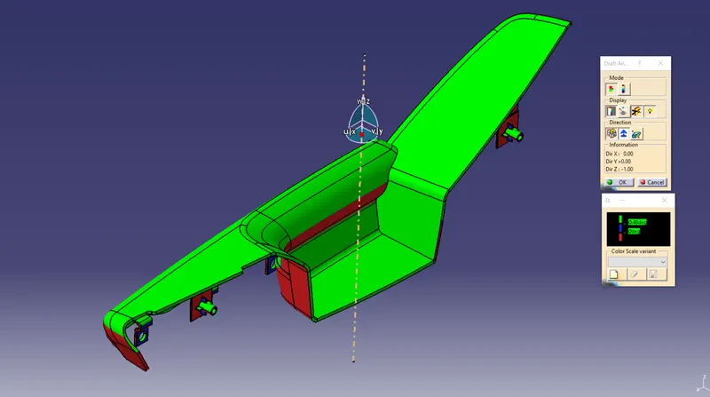
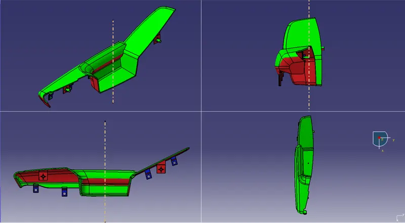
- Draft analysis using the side core axis
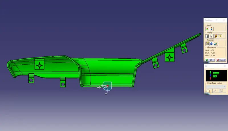
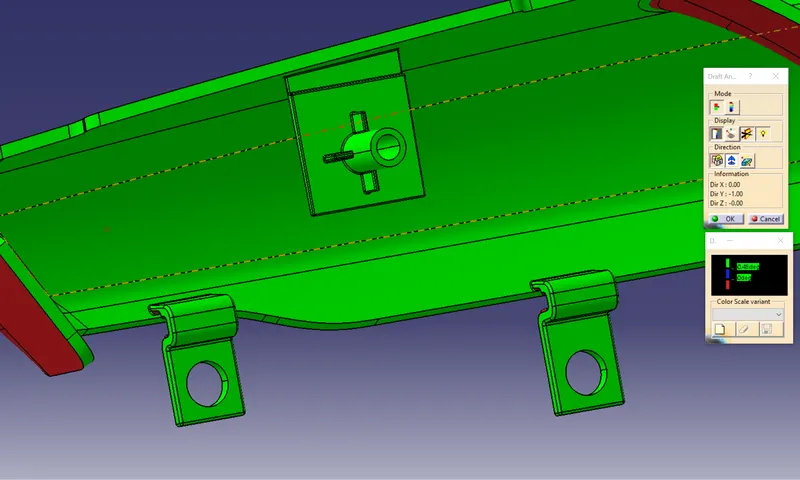
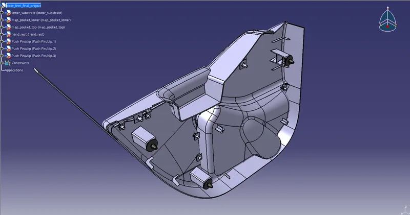
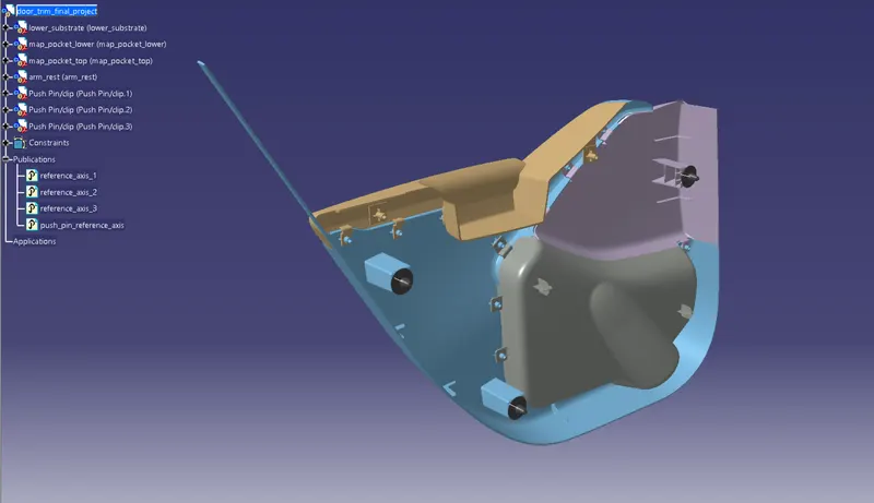
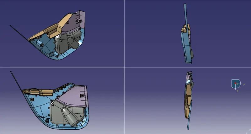
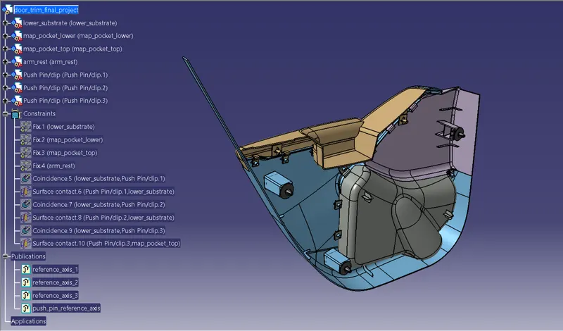
FINAL ASSEMBLY OF DOOR TRIM PANELS
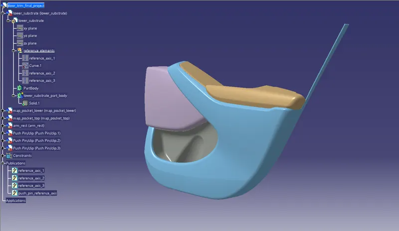
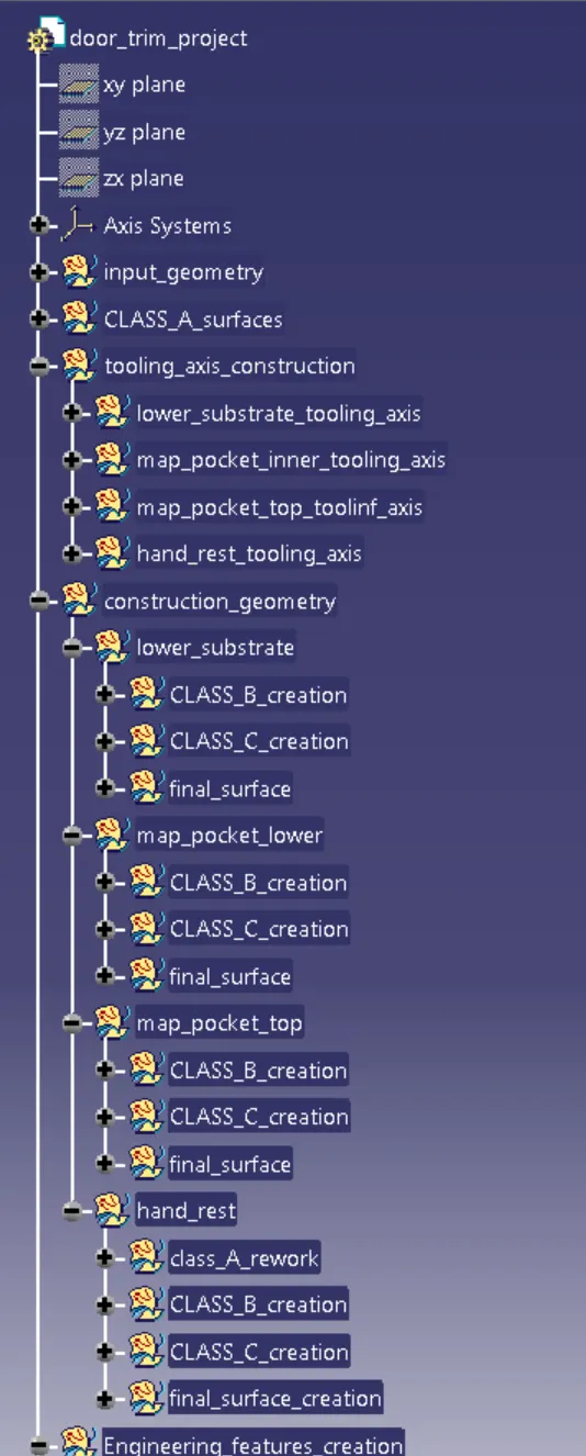
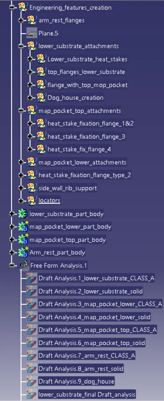
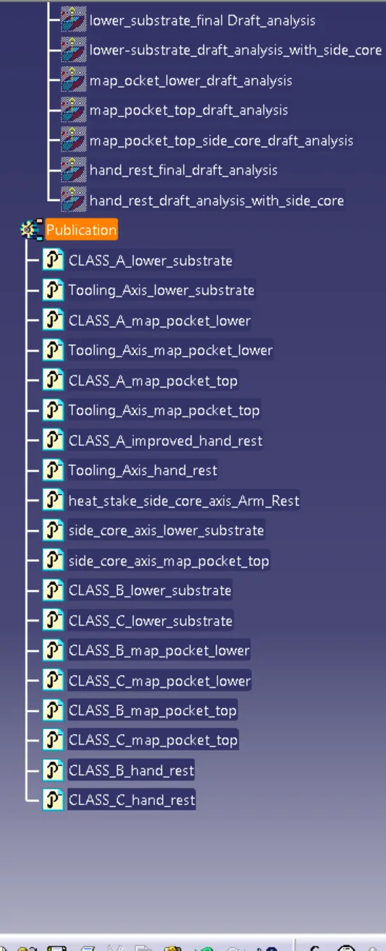
The expanded Tree Structure for the geometrical set and the Part Body
Conclusion
i hereby successfully completed the Door Trim final project using the given CLASS-A surfaces considering the OEM standards and engineering guidelines.