Roof challenge
ROOF CHALLENGE
An automobile roof or car top is the portion of an automobile that sits above the passenger compartment, protecting the vehicle occupants from sun, wind, rain, and other external elements.
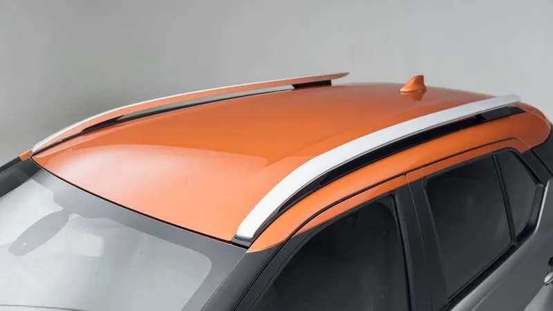
AIM - Design of an Automotive Roof
1. OBJECTIVES -
- To design Front Roof Rail
- To design Rear Roof Rail
- To design Centre Roof Rail
- To design Bow Roofs
- To find Moment of Inertia of Bow Roofs
- To perform Draft analysis on all the Rails and Bow Roofs
- To check the Roof for Heat Distortion criteria
- To check the Roof for Snow Load criteria
While designing the Roof, these following design considerations have to be taken into account
- Visibility Criteria
- Head clearance
- Curvature Study
- Heat distortion and Snow load Criteria
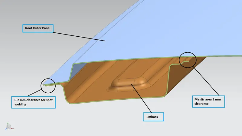
- Clearance of 5 mm should be present between outer roof rail and Front roof rail, Rear roof rail, bow roof, and Reinforcement centre where mastics are used for adhesion.
- Thickness for all sheet metal parts - 0.75 mm.
- All edges should have fillets and there should not be any sharp edges present.
2. Design of Roof and its main components using Siemens NX Cad software Are as follows
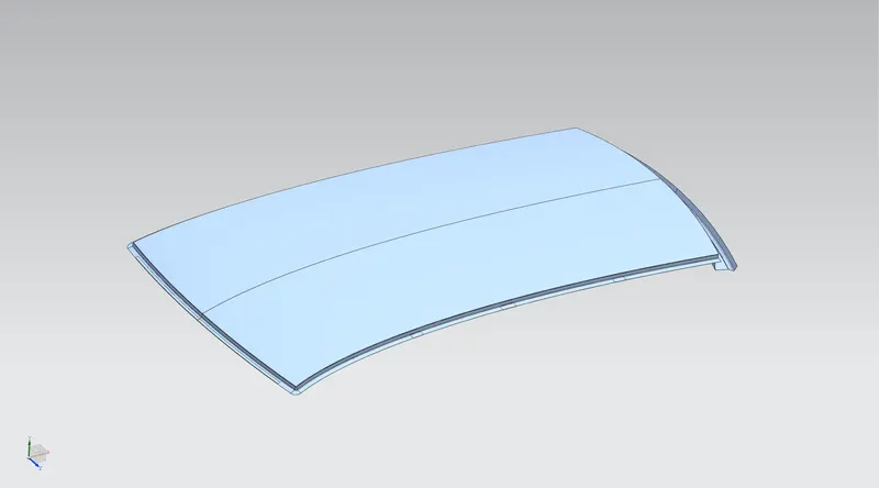
2.1 Roof Panel
The roof has an outer panel which is the styling part.
2.2 Front Roof Rail
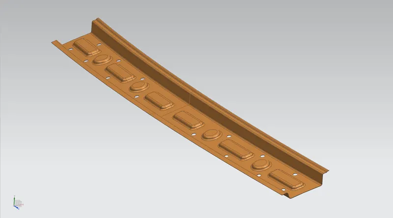
The front roof rail provides provision for the windshield glasses. Visibility criteria and headroom clearance have to be followed while designing the front roof rail.
Embosses are created to improve the strength of the component.
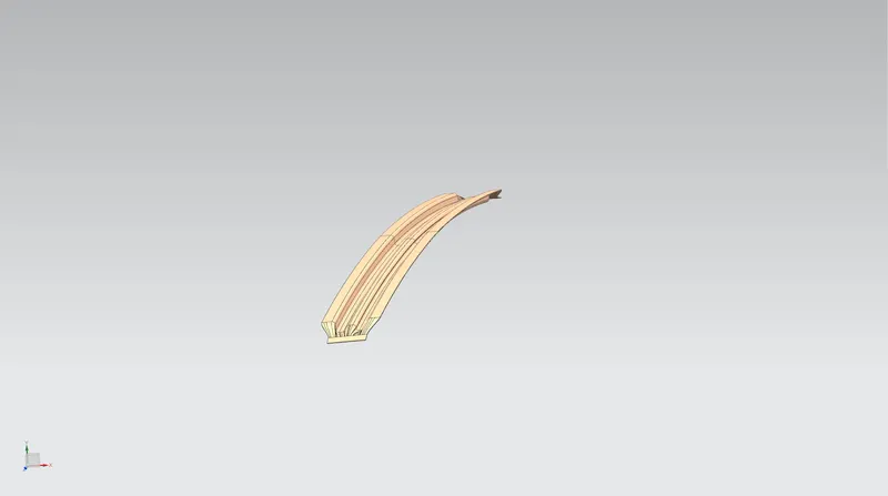
2.3 First Bow Roof
First bow roof is placed in between the front roof rail and centre roof rail. They are provided to enhance the localized strength and stiffness of the roof and are attached directly to the bottom of the roof with either spot welding or with the help of Mastics.
2.4 Centre Roof Rail
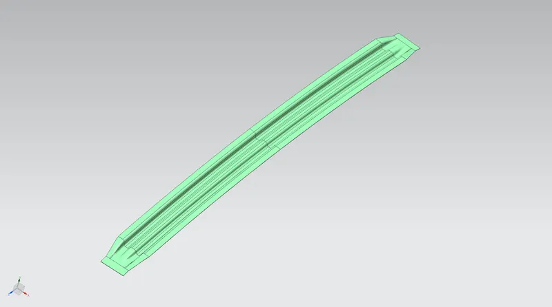
Centre roof rail is placed somewhat at the near centre of the roof to provide more strength and stiffness at the centre region.
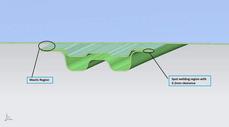
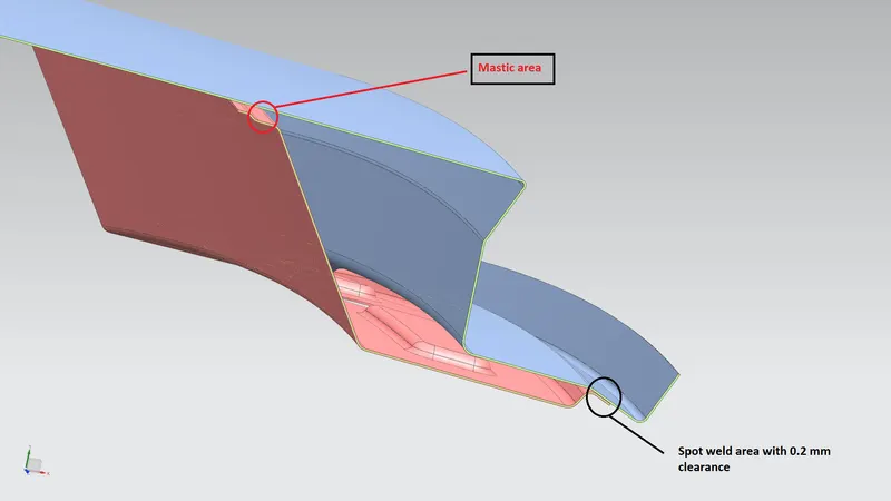
Overall length of the roof rail is 80 to 90 mm and 5 mm gap are provided for mastic region and 0.2mm for spot welding at the ditch area.
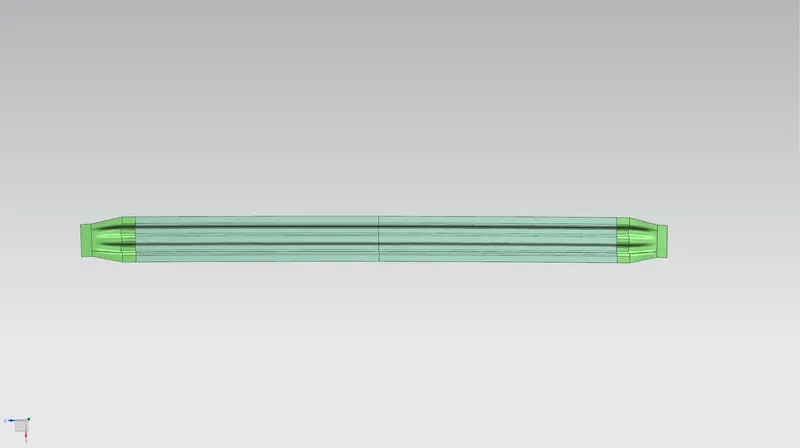
2.5 Centre Roof Rail with Reinforcement when sun roof is present
Here an additional reinforcement is provided on the centre roof rail which will be spot welded on it.
2.6 Second Bow Roof
This bow is provided in between the Centre roof rail and Rear roof rail to increase strength and stiffness of roof at the section.
These are attached directly below the roof panel with the help of mastic sealant and spot welding at the ditch area.
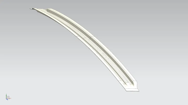
2.7 Rear Roof Rail
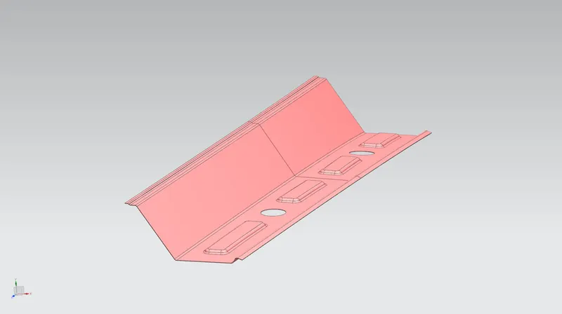
The Rear roof rail has hinge mounting for the back door. It is attached at the portion where the back door meets with the roof.
Embosses are created to improve the overall strength of rear roof ail.
5mm clearance provided between RRR and Roof outer panel for mastic implementation and 0.2 mm clearance given between the ditch area and RRR for spot welding process.
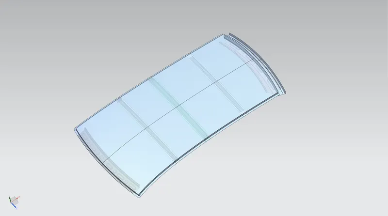
2.8 Roof Assembly
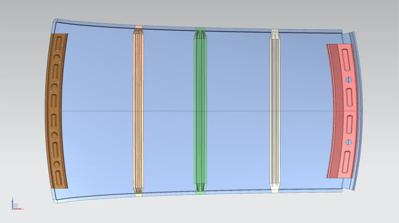
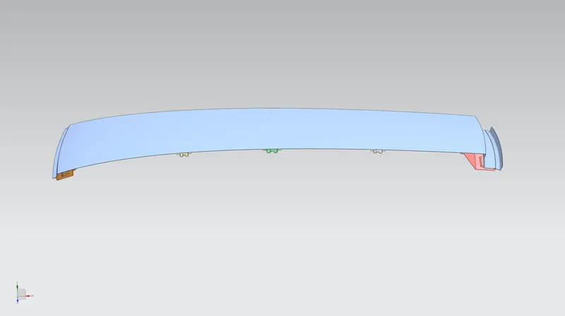
3. Draft analysis
Sheet metal parts are generated from a press tool or some forming tools, maybe the plastic parts which generally come out from the plastic moulds and maybe the casting parts, all such kind of parts required some face on the surfaces which are parallel to the tooling direction.
if we don't provide a draft on the surface then the tool will not come out and tool motion will destroy the surfaces or also reduced the finishing of surfaces.
Draught angles are designed in such a way that they will assist depart rejection. By doing so we have a reduced cycle time and improved productivity. Draft value for a particular part is mostly decided by the material used for making it.
- Draft analysis of Roof Outer Panel
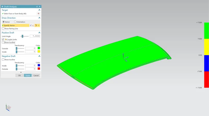
- Draft analysis of Front roof rail
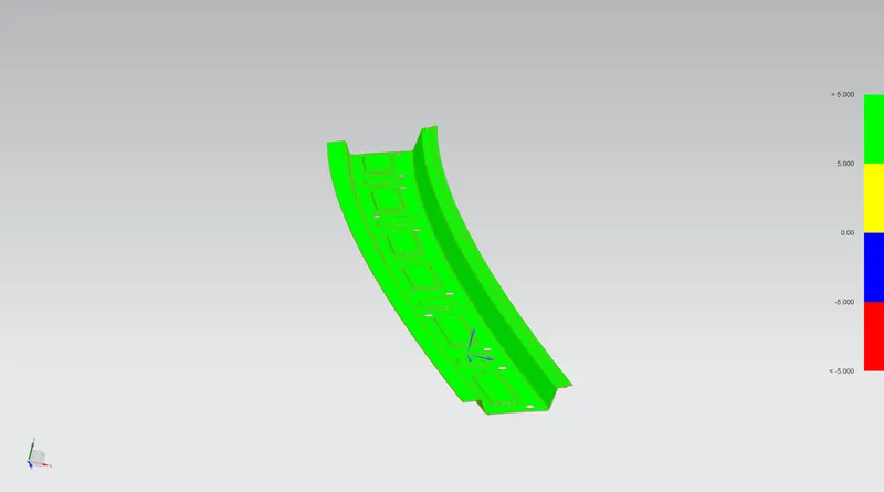
- Draft analysis of First bow roof
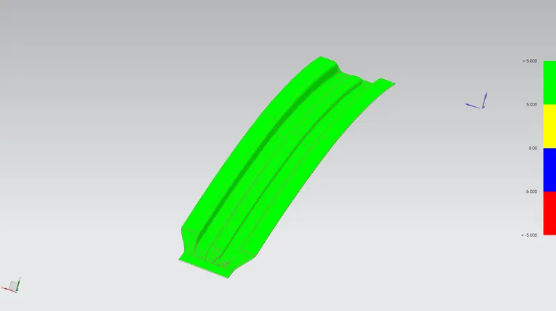
- Draft analysis of Centre Roof rail
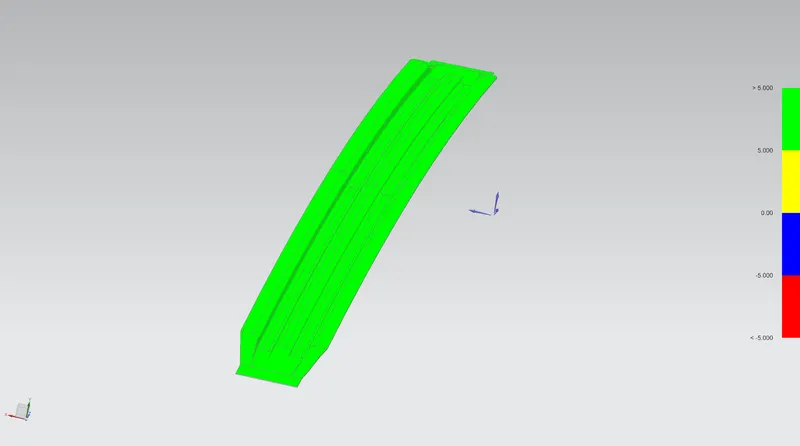
- Draft analysis of second bow roof
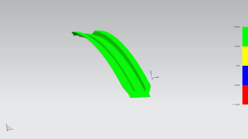
- Draft analysis of Rear roof rail
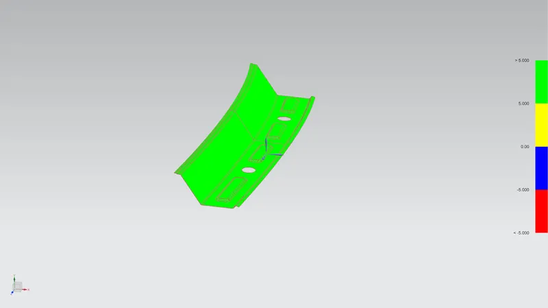
4. Some tests are conducted on Automobile Roofs in order to find out the capabilities of the component under various conditions.
4.1.Roll Crash test
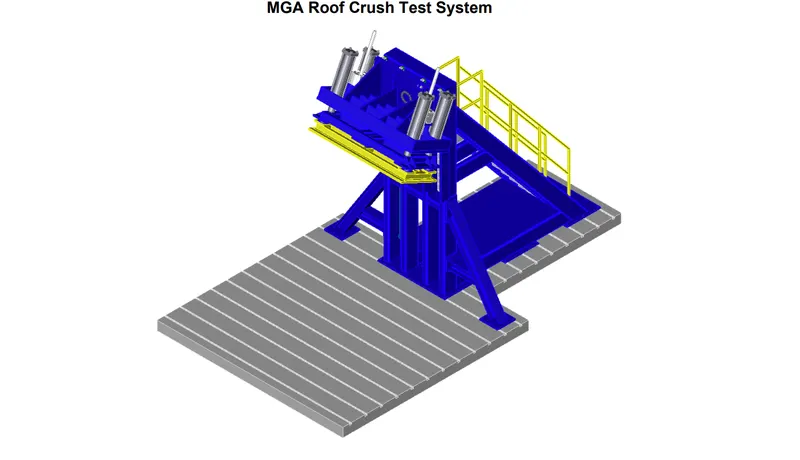
Roof strength evaluations are conducted on a quasi-static test system manufactured by MGA Research
The system consists of an upright assembly and an attached loading head that can
be fixed at varying heights from the ground as well as at pitch angles ranging from −5 to +5 degrees to
accommodate testing on the driver or passenger side. The roll angle is permanently fixed at 25 degrees.
Four hydraulic actuators control the movement of the platen along two linear guides. The entire system is
mounted on a T-slot bed plate anchored to the floor of the test facility.

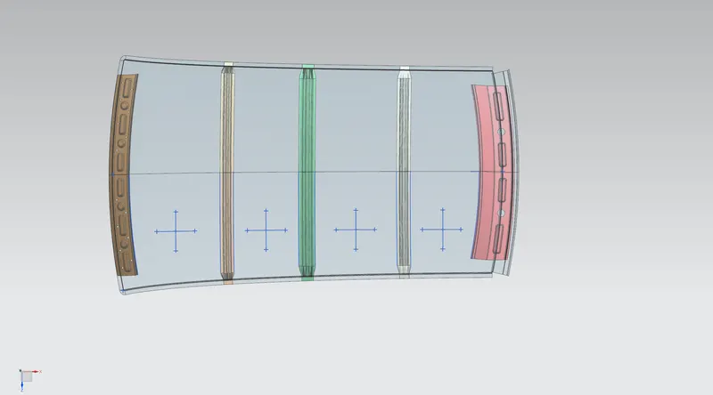
4.2.Heat Distortion Criteria
Heat distortion analysis plays a very important role in the strength of roof panel.
This study is used to predict the heat distortion temperature where the material starts to soften when exposed to a fixed load at elevated temperature.
To avoid any bending, damage or any other external effects due to temperature can be calculated using the heat distortion formula.
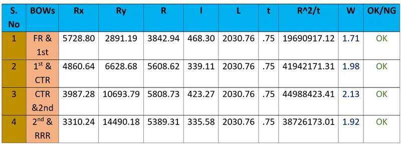
Bow–Roof Prediction Formula

Where,
L = Roof Length in X-Direction[mm](Roof dimension in 0-Y)
R = Roof curvature
R = 2(Rx*Ry)/(Rx+Ry)
Rx = X curvature
Ry = Y curvature
t = Roof plate thickness [mm]
l = Bow Roof Span [mm]
Judgment Condition
OK< 2.7
4.3. Snow Load Prediction
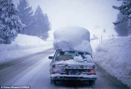
The purpose behind this analysis is to check the strength of the roof when snow is present on it acting as a load.
A roof should be designed in such a way that it should rebound to its original shape after the removal of snow.
Here is the formula for calculating the snow load

Where,
α = My x Lx2 x 10-12, My = Y(Ly-Y)
t = Roof plate thickness [mm]
Ly = Distance between the front and rear roof Rails on the Vehicle along with 0Y[mm]
Length of Roof panel with the centre point between Roof rail Front /Rear as the front and rear reference point.
Lx = Distance between the Left and Right end of the roof on the Roof BOW [mm]
The width of the roof panel is exposed on the surface.
Y = Distance from Front Roof Rail to Roof BOW [mm]
s = Distance for which Roof BOW bears divided load [mm]
s = L1/2 + L2/2
Iy = Geometrical moment of inertia of Roof BOW (Y cross-section) [mm4]
Rx = Lateral direction curvature radius of roof panel Y cross-section on Roof BOW [mm]
Roof panel curvature Radius of the Length Lx in Front view
Ry = Longitudinal Direction curvature radius of the Roof panel X cross-section on Roof BOW [mm]
Roof panel X curvature radius of length s in Side view
Judgment condition
Qr ≥ 3.1


As from the above analysis, it is clear that the roof design has not satisfy the Snow load criteria. To achieve the Snow load criteria, we may opt to have some changes in the design. Some possible changes that may take to pass the snow load criteria are as follows,
- Redesigning the Bows to improve the overall strength and Moment of inertia.
- Adding more Bows to reduce the distance between the bows provided.
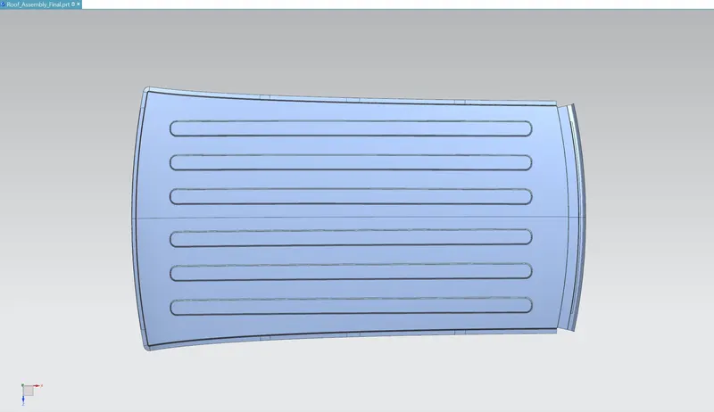
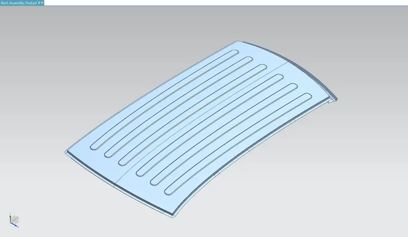
- Make some emboss structures on the roof panel which can drastically improve the strength of the outer panel and can withstand the snow load conditions.
- Communicate with the styling team to improve or change the radius of curvature for the styling part.
Action Taken to improve the Snow load criteria is adding some embosses on the roof panel, which will improve the strength and stiffness and results in better snow load condition.
Conclusion
I have successfully designed the car roof by considering all the design aspects, heat distortion criteria and snow load analysis using siemens NX CAD software.