Wiring harness design in CATIA V5 - 3D modeling Week 2 Challenge
Wiring harness design in CATIA V5 - 3D modelling Week 2 Challenge
AIM
To define the given connectors & Connector clip cad data as Electrical Connector using Electrical Part design Workbench. Define all the necessary properties of Connectors & Clip.
INTRODUCTION
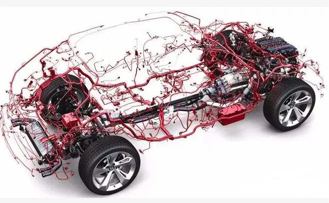
Wire harness connectors and terminals are basic components found in a wire harness. A wire harness, sometimes referred to as a wire assembly, is a set of multiple wires or cables in their own protective covers or jackets that are bundled into a single wire harness. Wire harnesses keep electronic or electrical systems organized to transmit signals, relay information, or electrical power.
Automobile wiring harness is the main part of automobile circuit network. As people on car safety, comfort, economy and emission requirement, car appliances configuration, function more and more, so a connect the electrical wiring harness is becoming more and more complex, become a link with contemporary car trouble, and therefore in car design and manufacturing is more and more attention. How to improve the comprehensive performance of automobile wiring harness has become the focus of attention.
The function of wire harness in the whole vehicle is to transmit or exchange the power signal or data signal of the electrical system to realize the functions and requirements of the electrical system.
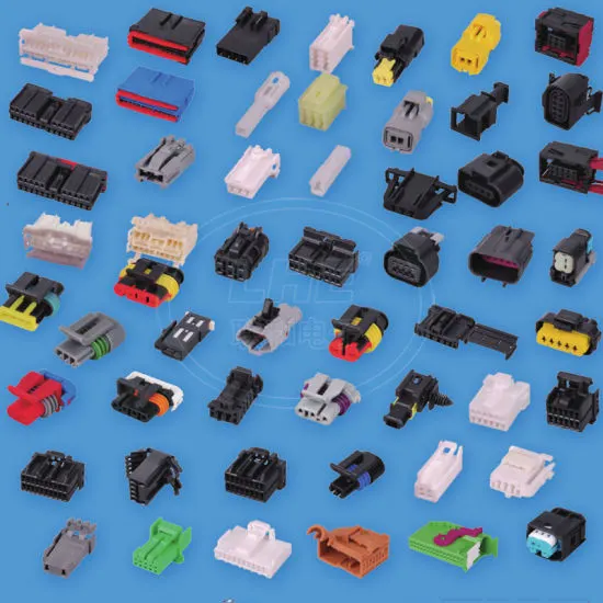
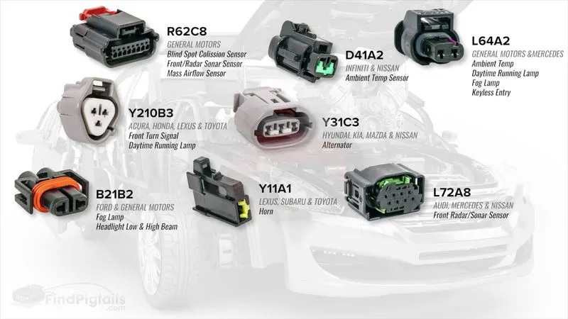
Connectors are the electro-mechanical devices used to form a continuous electronic signal to connect wire harnesses to a power source or circuit. On a basic level, connectors consist of male-ended plugs and female-ended jacks that can be joined together to relay an electronic signal. They are the familiar mating pair of polarized multi-pin connectors with wire leads. A male-ended plastic housing with release fits into a snap-mounted female-ended chassis mounting. The pair can be connected or disconnected easily and come in a variety of sizes, shapes, materials, quality, and dimensions—circular, header, pin, crimped, multitap—which are dependent on the application.
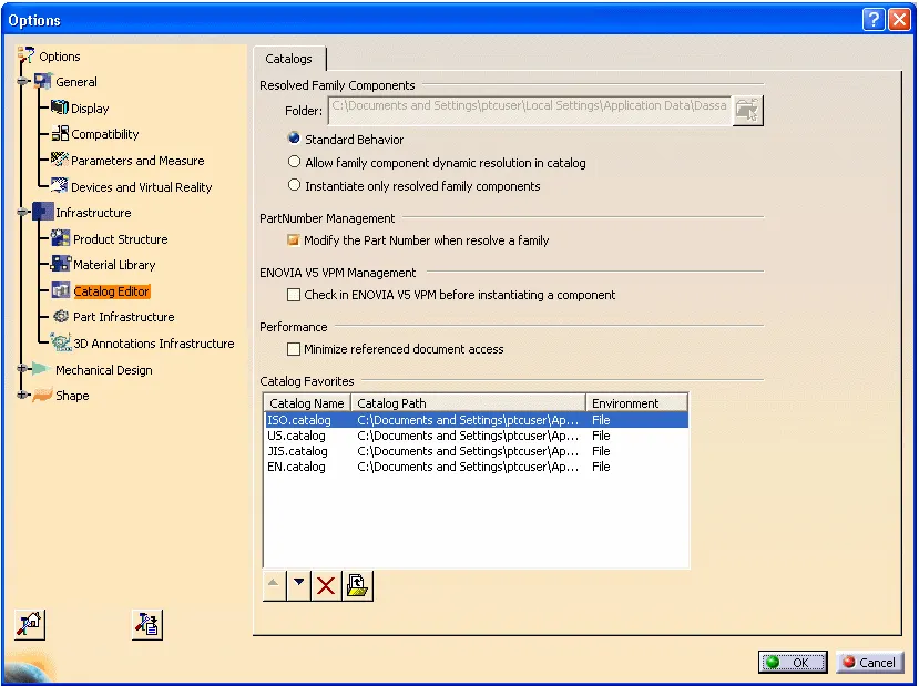
A catalogue is a CATIA V5 document that keeps a list of references to other CATIA parts and features. A typical CATIA document is a generic family table with specific instances within a library context, with a
Use catalogues to insert their parts and features into other CATIA V5 documents. Catalogues provide the ability to manage and access their part standards in a centralized location, such as Windchill. Catalogues are tightly integrated with most of the CATIA V5 workbenches, including but not limited to assembly design, electrical design, electrical harness, and piping design.
OBJECTIVE
- Download the required part files from the given source link.
- Define the CAD data as electrical connectors using the electrical part workbench.
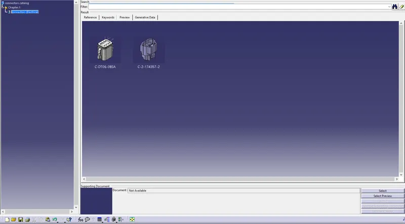
- Add the electrically defined parts to the Connector catalogue file for future reference.
- Using electrical Assembly Design workbench, create assembly of connector housing with the mounting clip.
DESIGN METHODOLOGY
Procedure of the connector for defining it electrically.
- First download the connectors and mounting clip from the given link source.
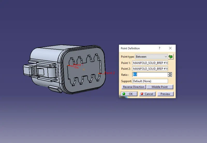
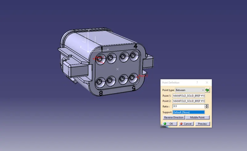
- Get into the mechanical part workbench to create required geometrical parameters. Create connector connection point and bundle connection point on the required sides of the CAD part.
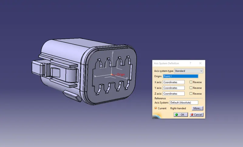
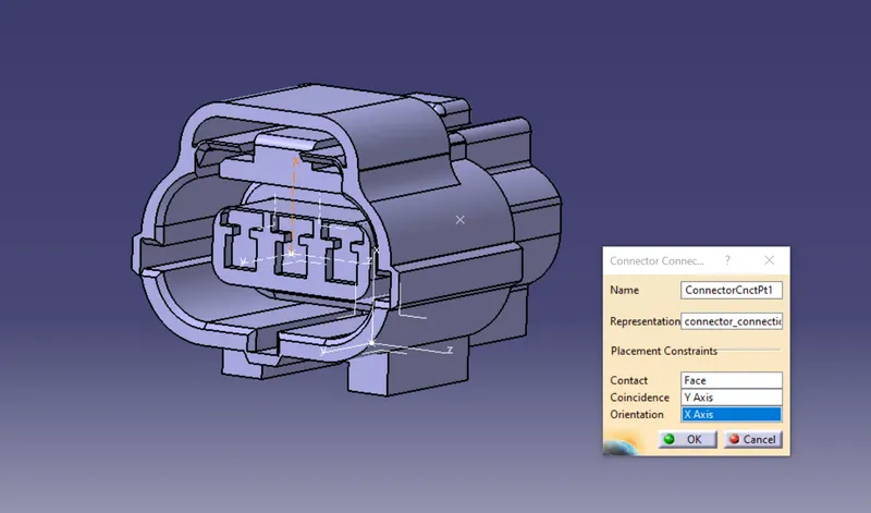
- Create axis system on the connector connection point such a way that the Y coordinate facing normal to the connector face, X coordinate facing towards the locking mechanism and Z coordinate facing to the top.
- Create cavity connection point for connectors having the cavity for mounting clips
Using the geometrical parameters created,
- Define part as electrical connector.
- Define bundle connection point.
- Define connector connection point.
- Define cavity connection point.
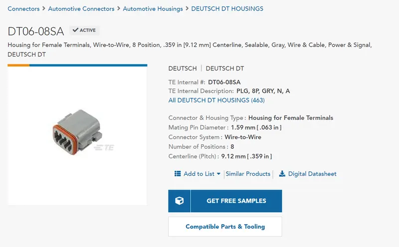
Connector Model 1
Deutsch DT06 – 08SA
( https://www.te.com/usa-en/product-DT06-08SA.html)
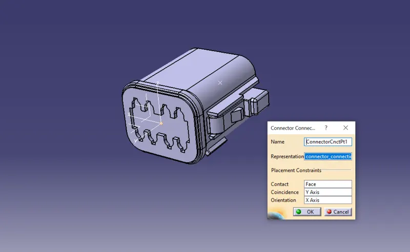
- Create connector connection point
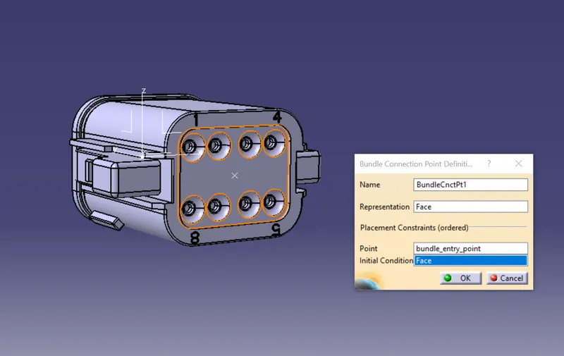
- Create bundle connection point
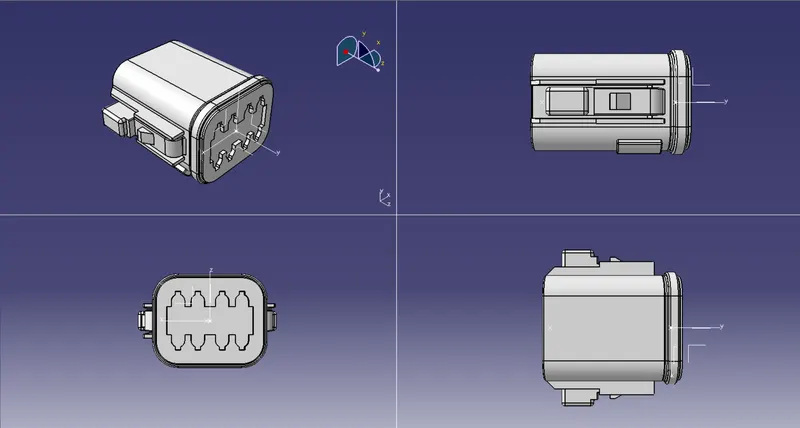
- Create connector connection axis system
- Define connector as electrical part
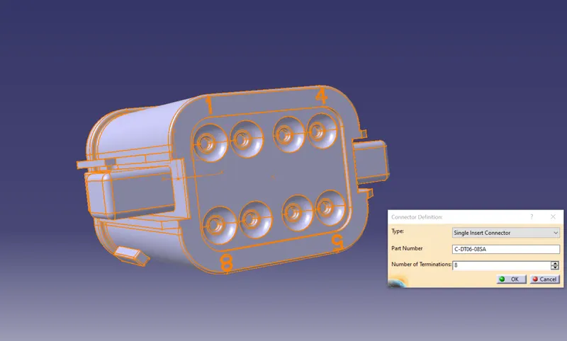
- Defne connector connection point
- Define bundle connection point
3D Part model in various orientations (Isometric, Front, Side, and Top View)
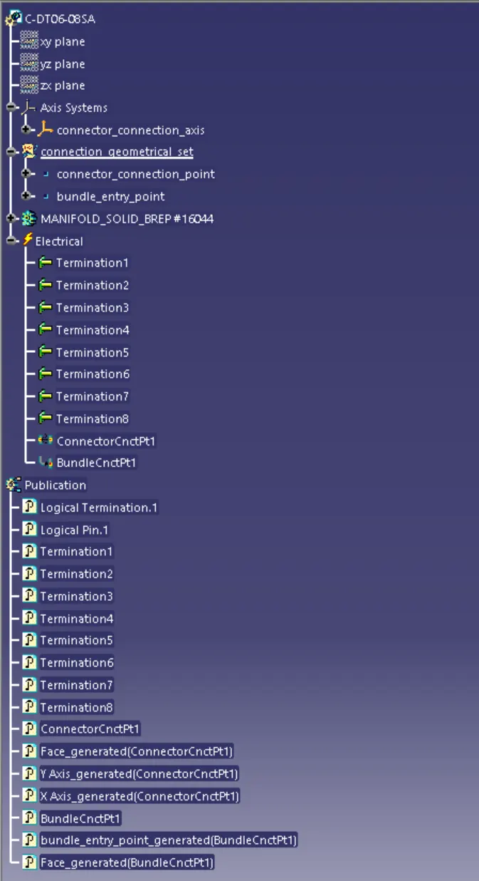
The expanded Tree Structure for the geometrical set and the Part Body
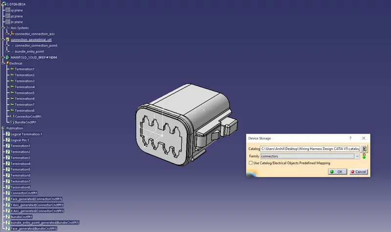
Connector added to the catalogue file.
Connector model 2
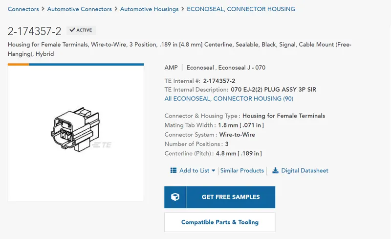
Tyco 174357-2 (https://www.te.com/usa-en/product-2-174357-2.html?source=header-match)
- Create connector connection point
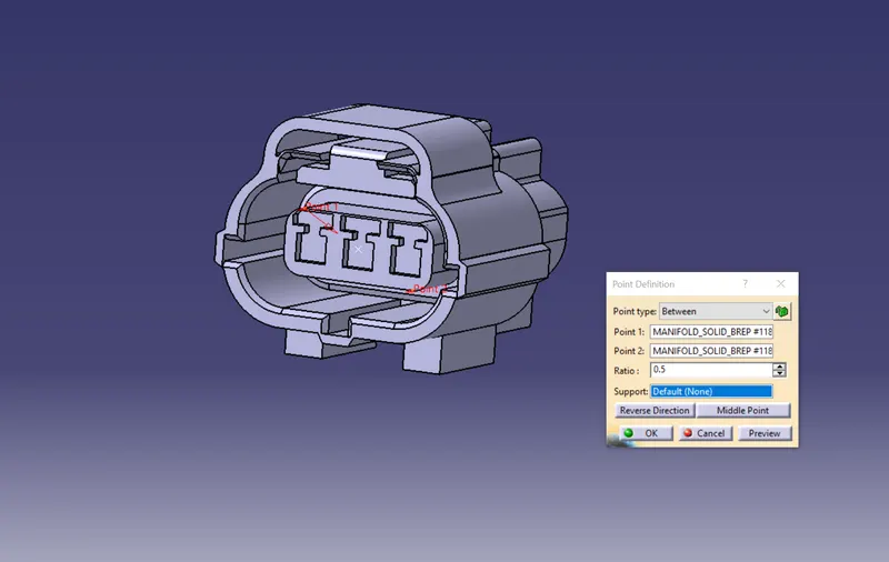
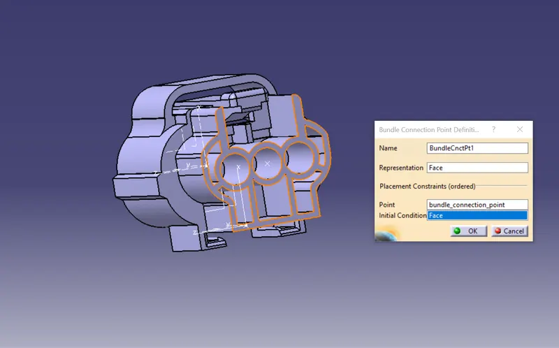
- Create bundle connection point
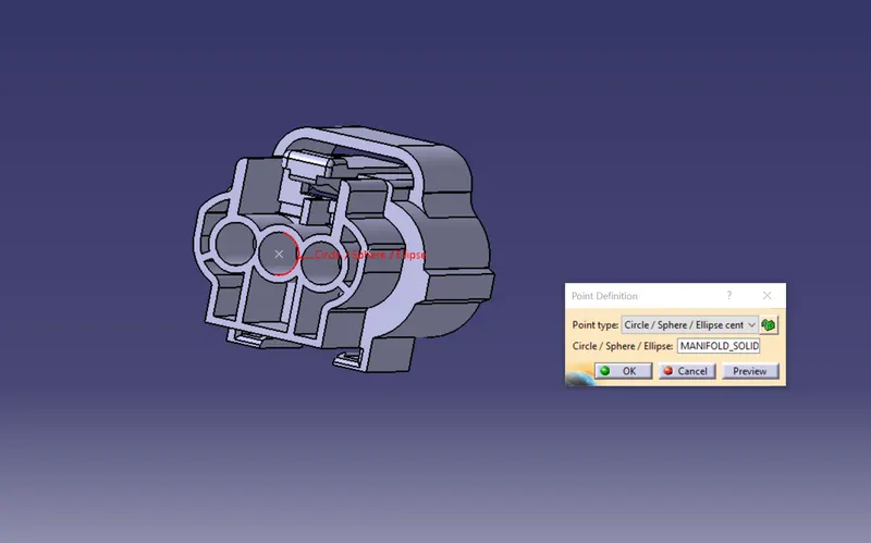
- Create connector connection axis system
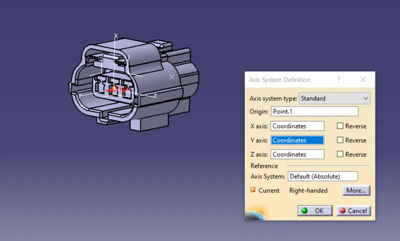
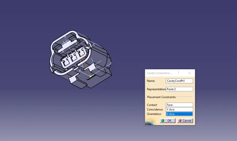
- Create cavity connection point
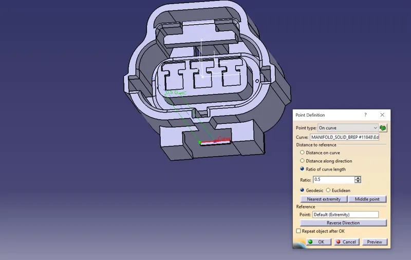
- Create cavity connection axis
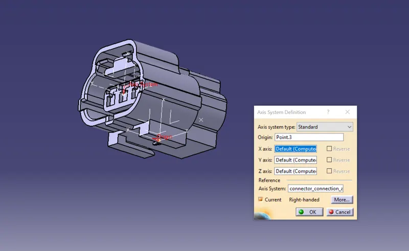
- Define connector as electrical part
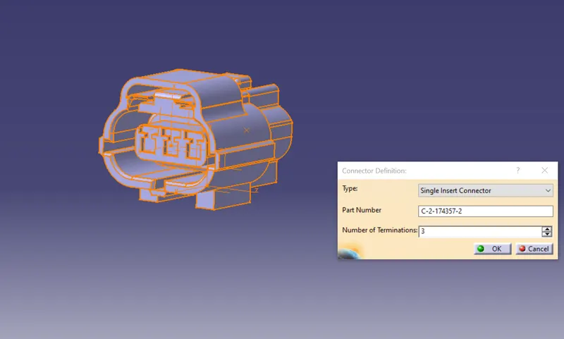
- Defne connector connection point
- Define bundle connection point
- Define cavity connection.
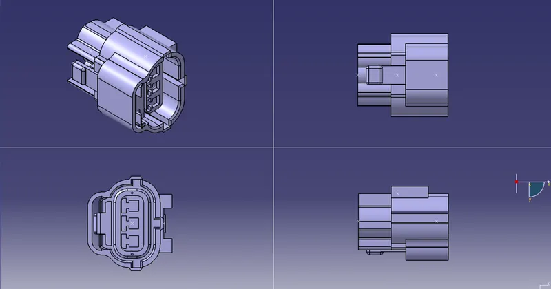
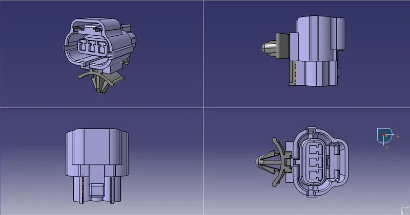
3D Part model in various orientations (Isometric, Front, Side, and Top View)
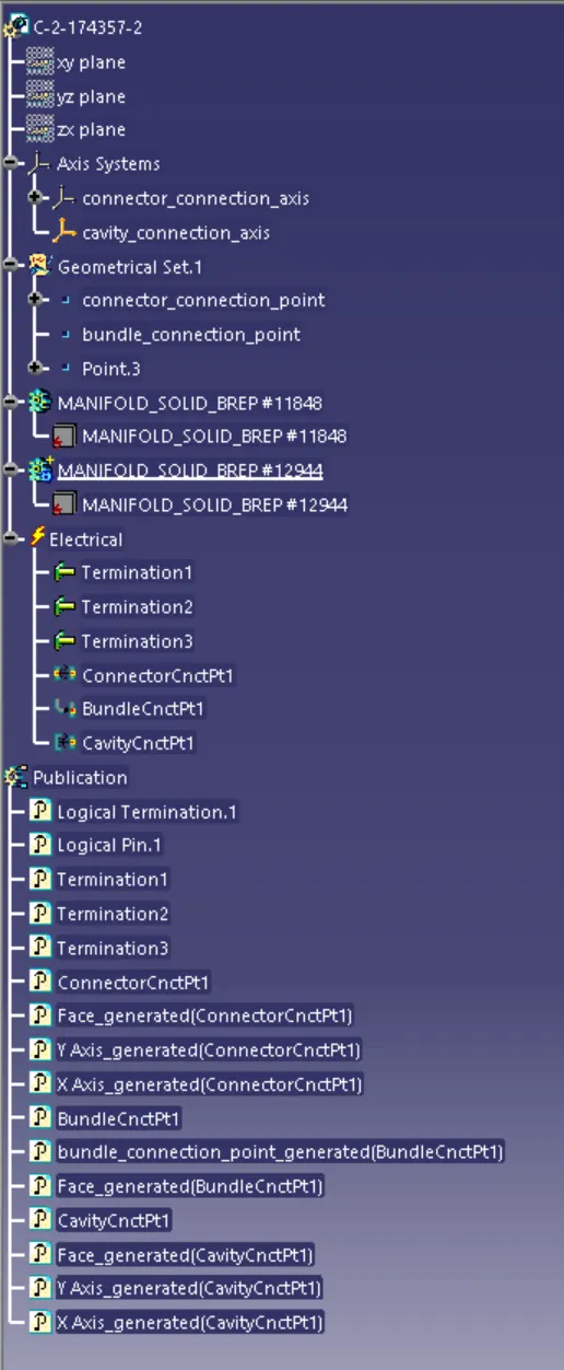
The expanded Tree Structure for the geometrical set and the Part Body
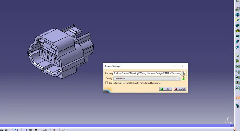
Connector added to the catalogue file.
Mounting Clip part
Procedure for mounting clip
- Download the required mounting clip CAD part from the given link.
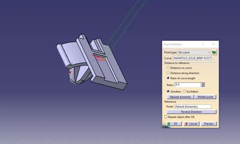
- From mechanical part design workbench, create cavity connection point on the required face.
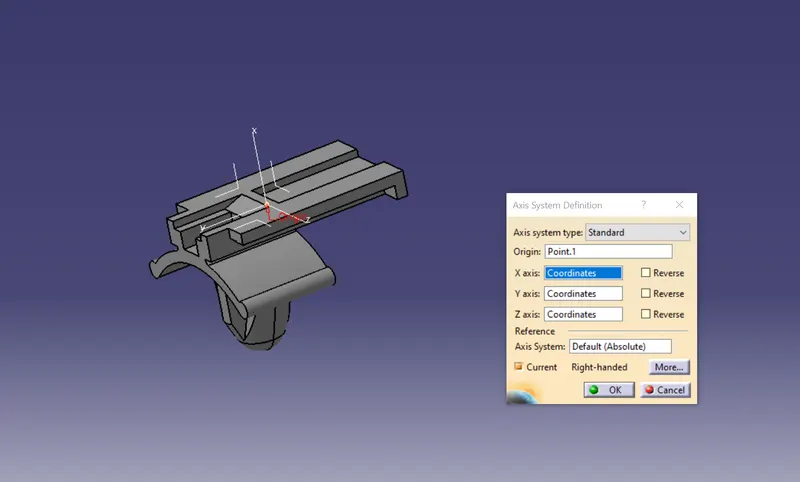
- Then create Axis system orientation same as the axis system on the connector housing.
Go to the electrical part workbench,
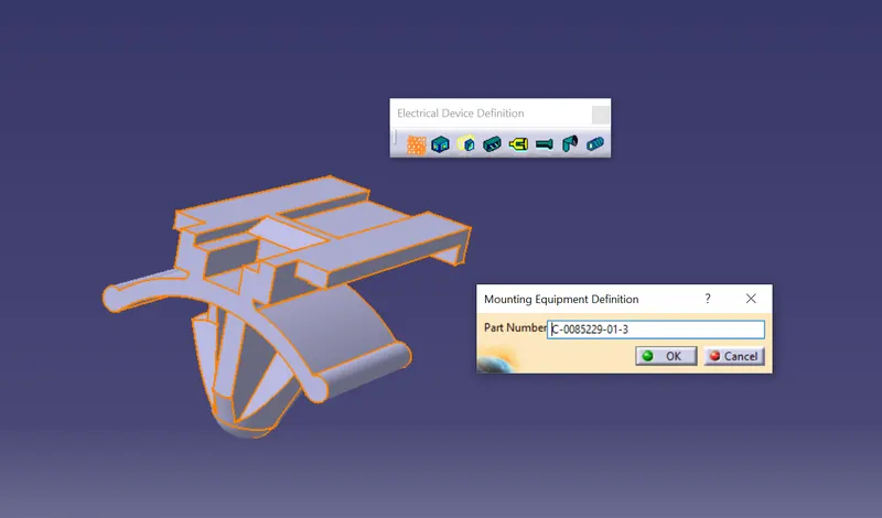
- Define mounting equipment
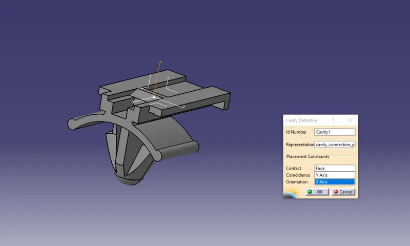
- Define cavity
Tyco 85229-1 – (https://www.te.com/usa-en/product-85229-1.html?q=85229&source=header)
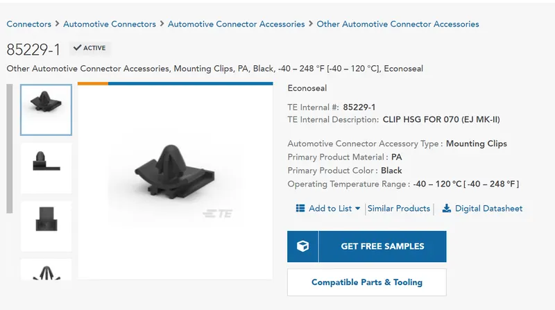
- Creating the cavity connection point
- Creating the cavity connection axis
- Defining mounting equipment
- Defining part as cavity
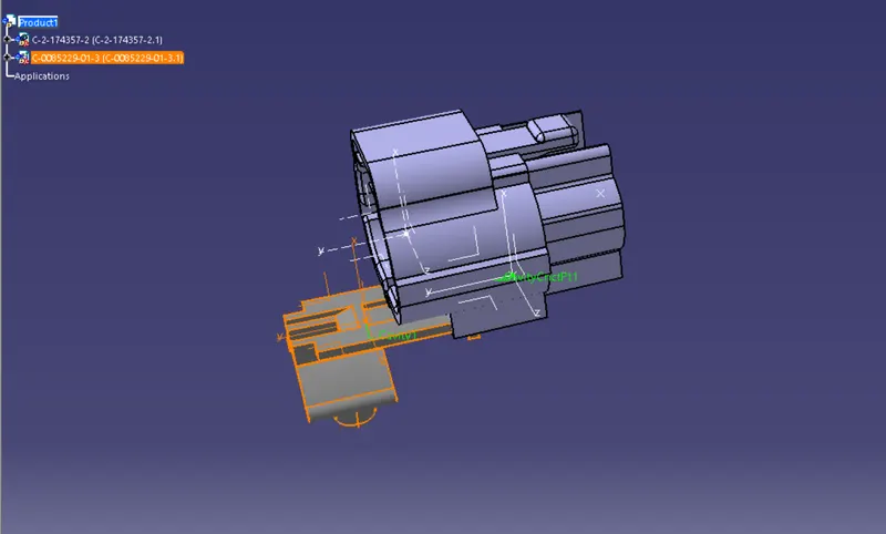
Assembly of connector and mounting clip
- Copy and paste the connector and mounting clip into the electrical assembly design workbench.
- Either using the compass in electrical assembly design or move manipulation option in the mechanical part design, re arrange the position of components to the desired positions.
- Using Connect electrical device option, assemble the connector and mounting clip.

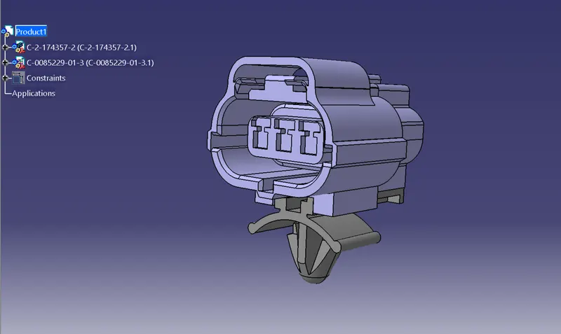
3D Part model in various orientations (Isometric, Front, Side, and Top View)
Connector Catalogue file
Conclusion
The given connectors and mounting clip are defined as electrical parts with the help of required geometrical parameters and assembled together. Also connectors are added to the calatog file for future reference and use.