Week 8 - Challenge 2 - Switch Bezel Design
SWITCH BEZEL DESIGN- CHALLENGE 2
AIM
To create the Switch Bezel Plastic component using the given Class-A surface. To begin with, the tooling axis for the given Class-A Surface should be created meeting the requirements of the draft angle and at the end perform the Draft analysis on the model.
1. INTRODUCTION
A switch bezel panel is nothing but a part which consists of the switch panels for the power windows and also has some place to rest the passenger’s hand on it. It is assembled on the main door trim panels.
2. DESIGN CONSIDERATIONS
CLASS-A Surface
Class-A surface means visible surface. It gives the aesthetic of the component which is created by the styling team and gives to the part design engineer to create the part with all engineering aspects.
CLASS-B Surface
Class-B surface means thickness of a part it is not visible and is inside part. In other words, Class-B surface is a surface below a certain thickness from the class-A surface. This is the surface that contains engineering aspects of a model.
CLASS-C Surface
Surface that joins class-A and class-B surfaces is class-C surface. Class C is often specified for interior surfaces not readily visible, surfaces that will be covered by another part when assembled
3. THE DRAFT ANALYSIS AND THE TOOLING AXIS CREATION.
The Draft Analysis allows the user to easily analyse a part for proper draft angle. A Draft Angle describes the amount of taper for molded or cast parts perpendicular to the parting line.
Every part should clear the draft analysis test to ensure the feasibility and easy manufacturability of the component.
General guidelines for giving draft angle to a part are
- 0.5 degrees on all vertical faces is strongly advised.
- 1 to 2 degrees works very well in most situations.
- 3 degrees is minimum for a shutoff (metal sliding on metal).
- 3 degrees is required for light texture (PM-T1).
- 5 or more degrees is required for heavy texture (PM-T2).
Most of the parts require a minimum of 0.5 to 1 degree of drafting in order to eject from the mold without any difficulties, however 3 degree is widely accepted as the Norm.
Procedures to follow when performing the Draft analysis of the given Class-A surface are as follows
3.1 DESIGN PROCEDURE
The first thing to create the tooling axis is to analyse the class A surface through visual inspection.
To make sure that the given surface has no gap in between them. We can check it also with the help of Join or boundary commands.
Here the given surface has only one boundary which means the given surface has no patches or irregularities and it is good to go for further design procedures
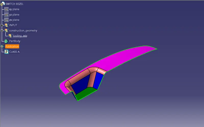
Procedure for creating the tooling axis
Tooling axis represents the opening and closing of the mold core and cavity during the manufacturing of the components. A plastic product designer should consider the best tooling direction to cutdown the cost of the component very less.
- Check the best tooling direction for the given surface.
- We can find out the best tooling direction by cross checking all the three axes.
- The ejection from the mold after manufacturing the interior trim must have the nominal 3-degree draft angle.
- Hence the tooling directions created by considering the above factor and bisecting method is used.
- Using the given class-A surface, extract the base surface of the pocket and create a midpoint on the extracted surface.
- create an axis system with respect to the point created.
- By looking the A-surface, we can say the best tooling direction can be made along the z axis.
- Hence, we need to check whether all the faces of the walls clearing the tooling direction. For that,
- create a positioned sketch on the y-z plane and using the project 3D element, project the wall faces on the y-z plane.
- Then create 2 lines and make it coincide with respective projected faces. And then with the lines created, a bisecting line can be made.
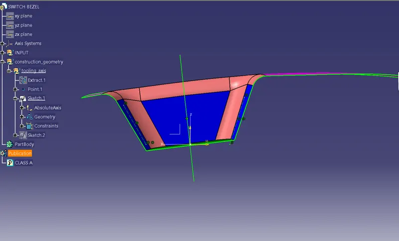
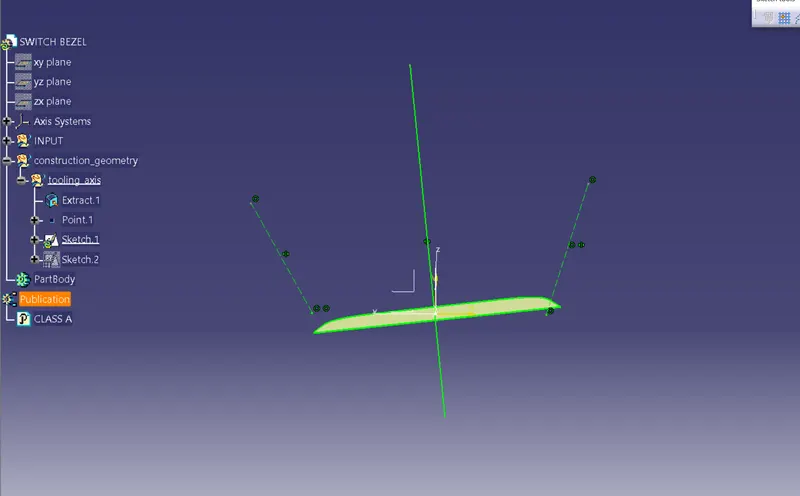
- Now considering the wall face on the x direction, create a sketch on the x-z plane and now we have face only on one side. Create an intersection or project the surface and create on line on it which coincide with wall.
- Now for the other wall create a line on the point we created earlier and make it at an angle 6 degree with the face.
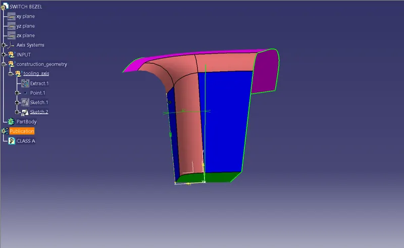
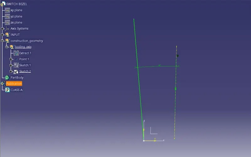
- By doing this procedure we get the second line for creating the Main Tooling axis.
- Creating a bisecting line with the two lines created above will get the desired Tooling Axis for the switch bezel component.
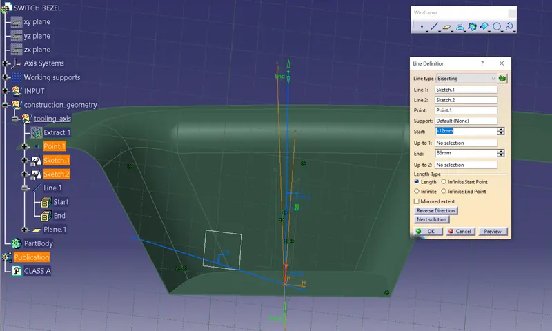
- The figure shows the Class-A surface with Tooling Axis
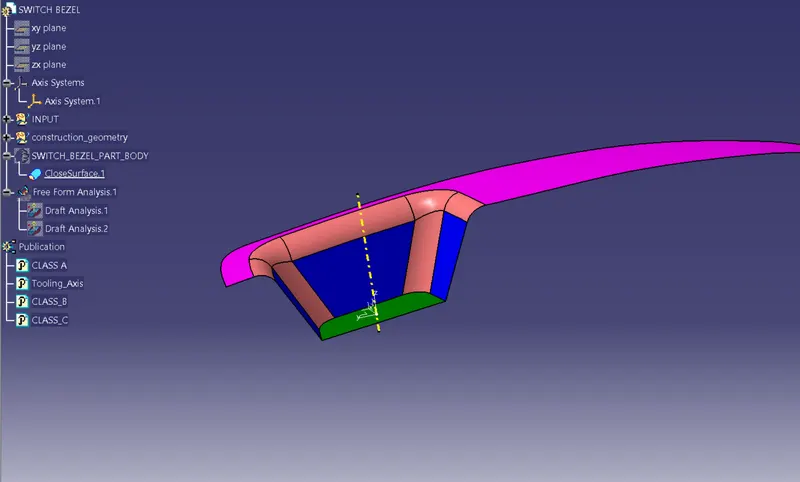
Draft analysis for the given CLASS-A surface
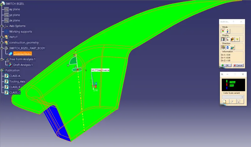
The Draft Analysis command enables you to detect if the part you drafted will be easily removed. This type of analysis is performed based on colour ranges identifying zones on the analysed element where the deviation from the draft direction at any point, corresponds to specified values.
Draft analysis is done after determining the tooling axis, draft analysis is used to check whether the minimum draft (3 degrees) is maintained or not.
Procedure for performing the draft analysis are as follows
- Change the view mode of the component to be in customized parameter mode and then select the shading mode as materials.
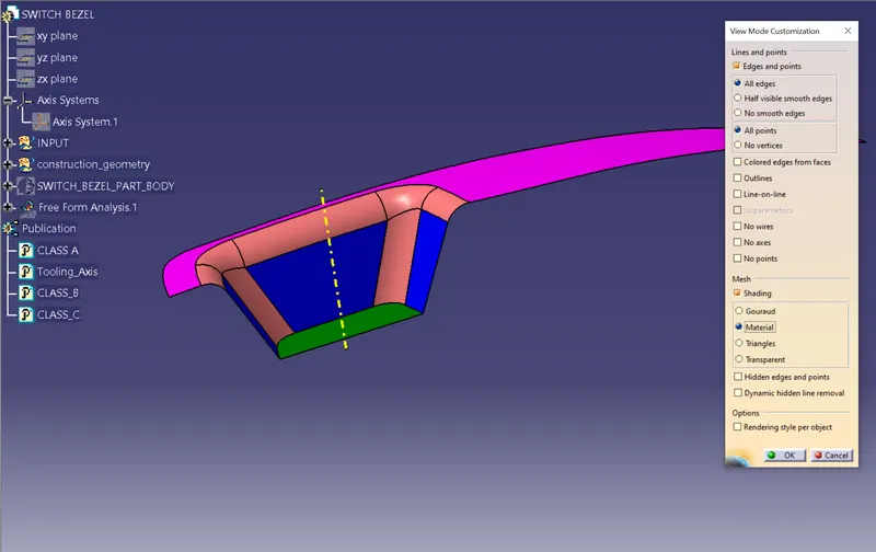
- Then open the featured draft analysis tool from the insert menu.
- Then click on use the compass to define the current drafting direction and then drag and align the compass on the Tooling axis.
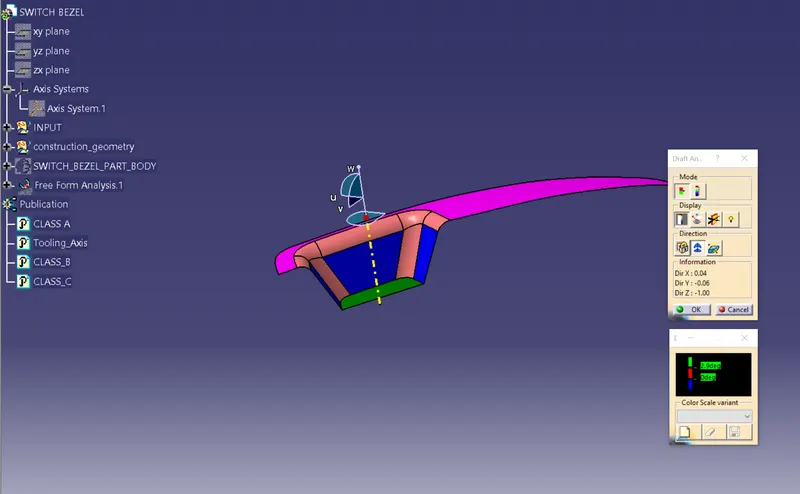
- Then lock the draft direction and perform draft analysis by clicking on the component.
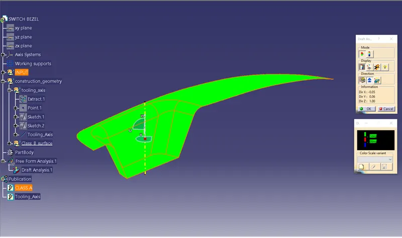
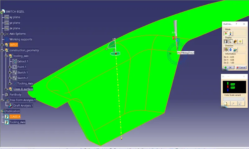
- The green colour shows the positive daft tooling direction and the given surface passes the draft analysis.
- Click on the analyses under the running point to check the draft analysis on the individual faces. It shows how much draft on specific points when we move the cursor point.
4. SURFACE-B CREATION
- Extract the top surface, wall faces and the base surface from the CLASS-A surface
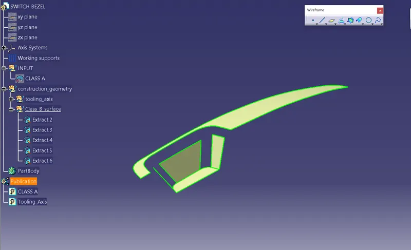
- Untrim the extracted surfaces one by one
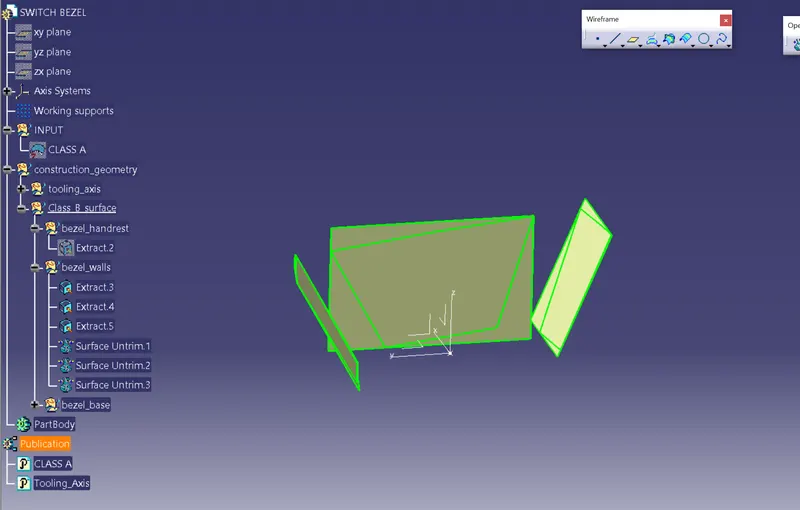
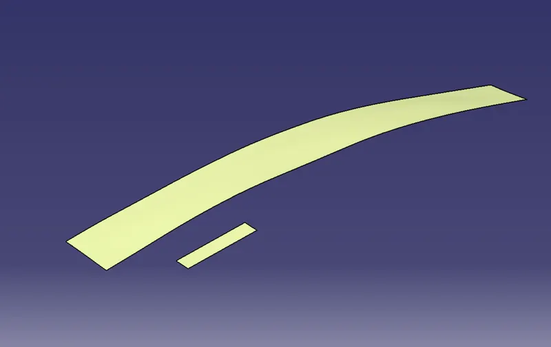
- Extrapolate the untrimmed surfaces to a required length
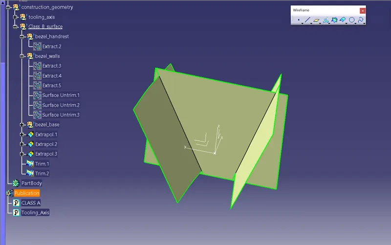
- Trim the extrapolated surfaces with each other to get the required shape.
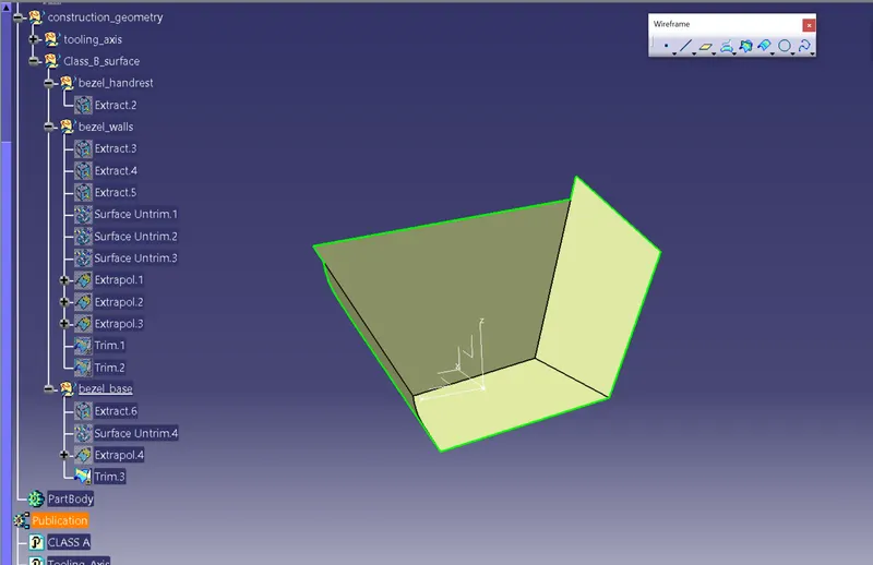
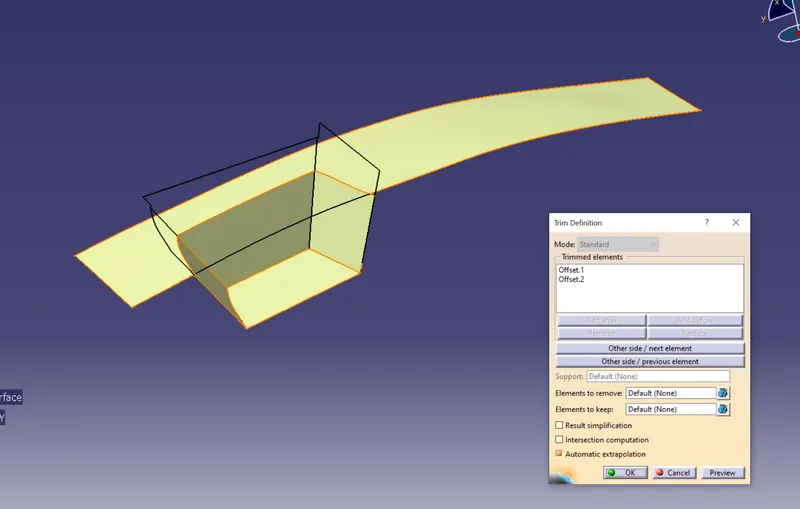
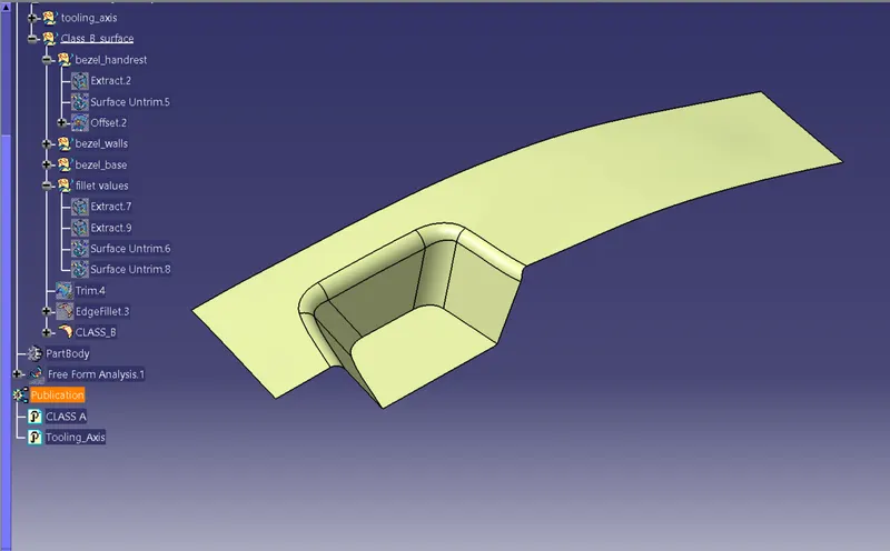
- Offset the trimmed surfaces to 2.5mm below the CLASS-A surface and then apply the required edge fillet values to the walls and the CLASS-B surface is created.
- Fillet radius for class B surface = fillet radius of class A surface ± wall thickness.
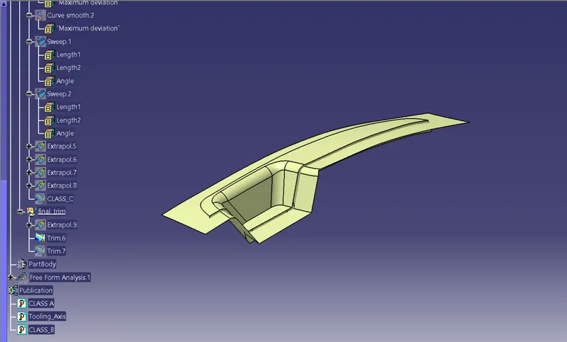
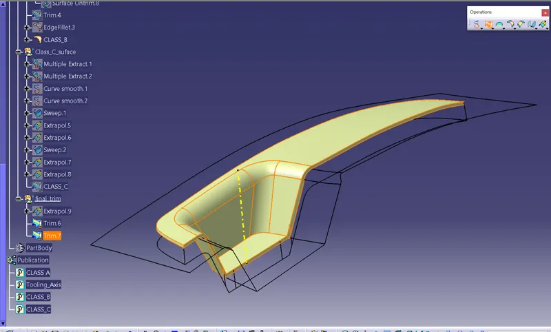
5. CREATION OF CLASS-C SURFACE
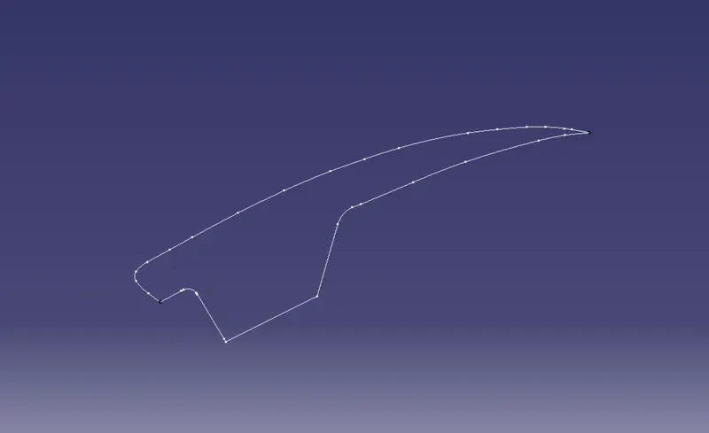
- First step is to create the boundary of the CLASS-A surface using the boundary command.
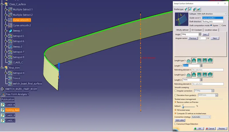
- Here we created the edge curves using the multi extract command and make the curves smooth using the smooth curve command
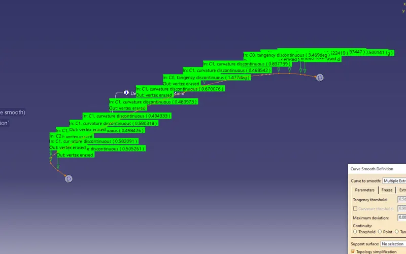
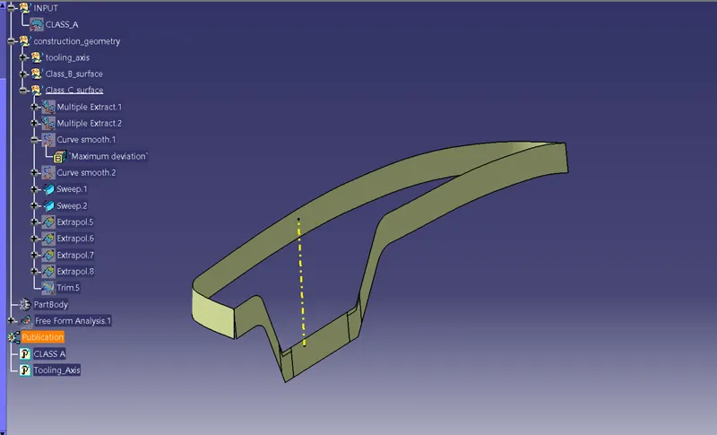
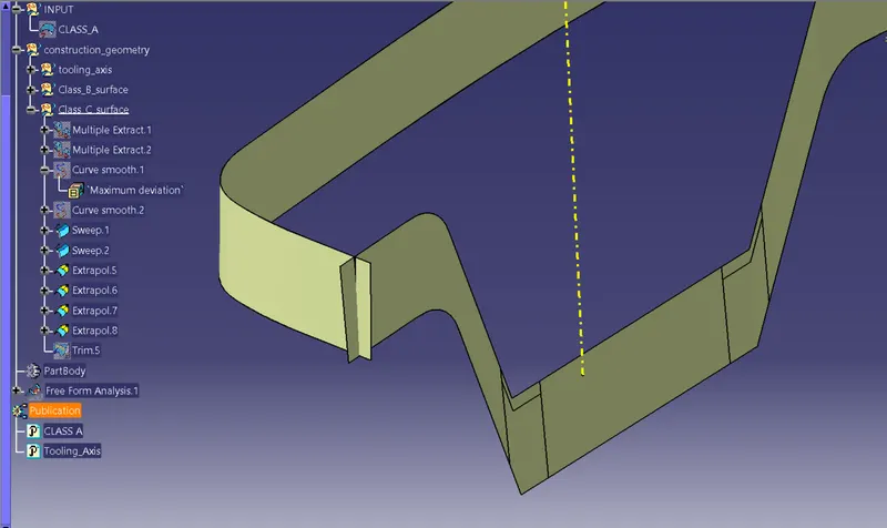
- Then use the sweep command to create the sweep profiles of the two curves created. The sweep surfaces are joined together by extrapolating it and trim with each other. Now the CLASS-C surface is Created.
- Always give draft to the outward direction(away from the tooling axis ), doing this would lead the intersection of parting line with class B surface boundary and hence the class A surface will come out to be a smooth surface without any extra material around it.

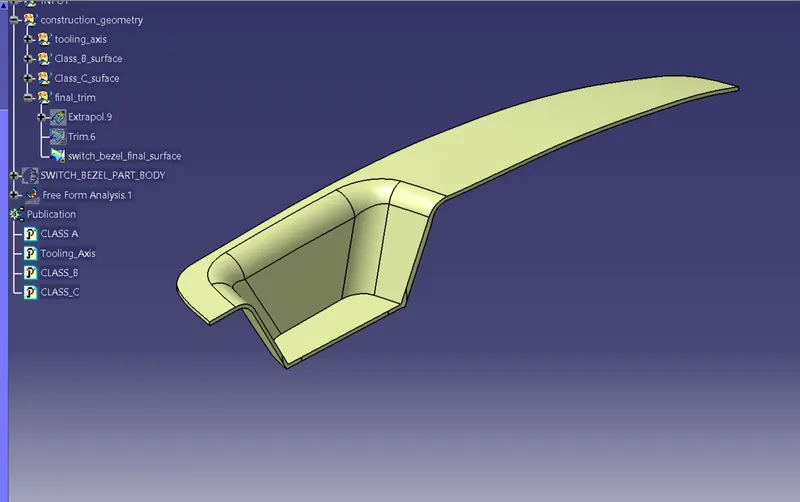
6. Creating the final surface of the switch bezel
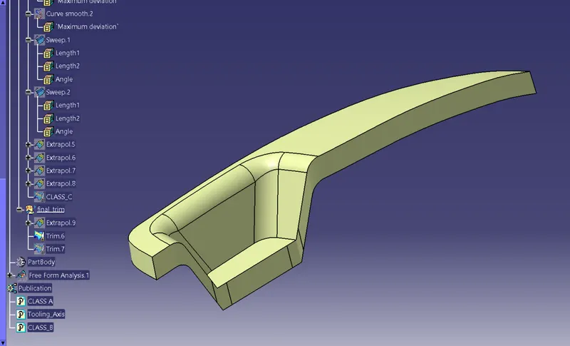
- Join the Class-A surface with Class-C surface and then trimming it with Class-B surface creates the required switch bezel final surface.
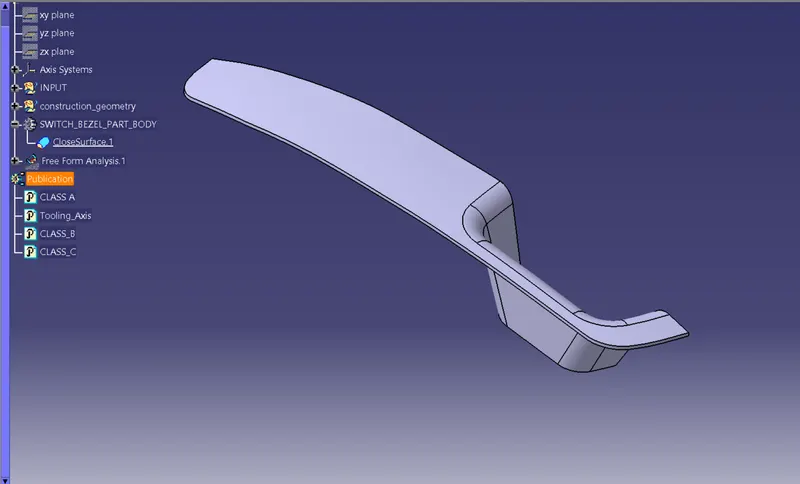
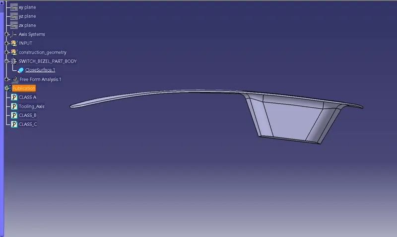
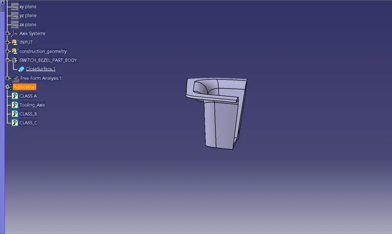
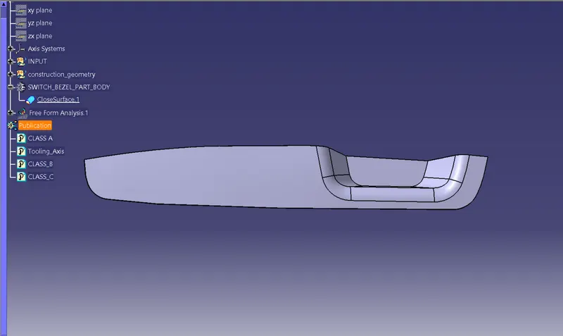
7. Go to the part design work bench and using the close surface command create the base bracket solid part body
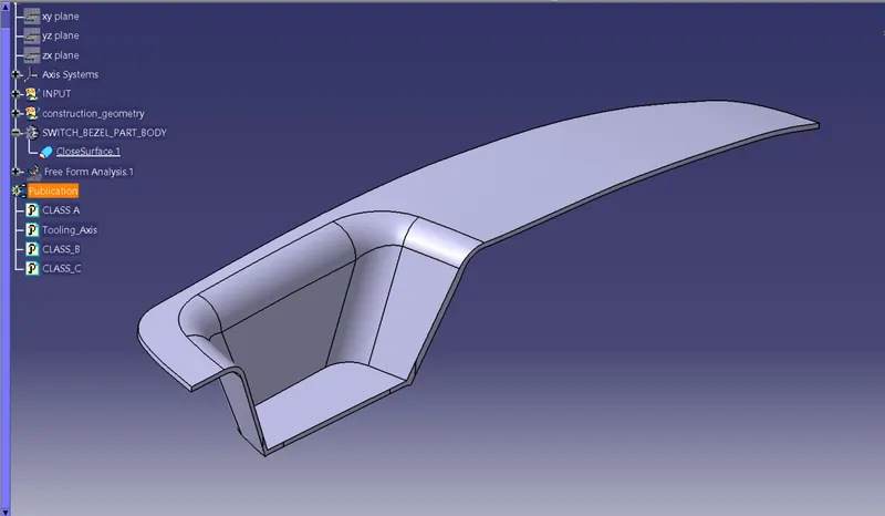
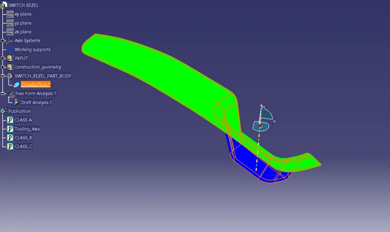
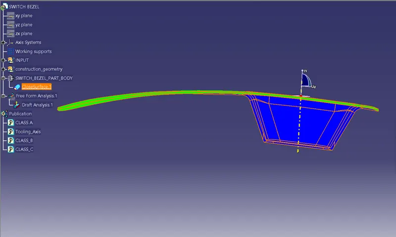
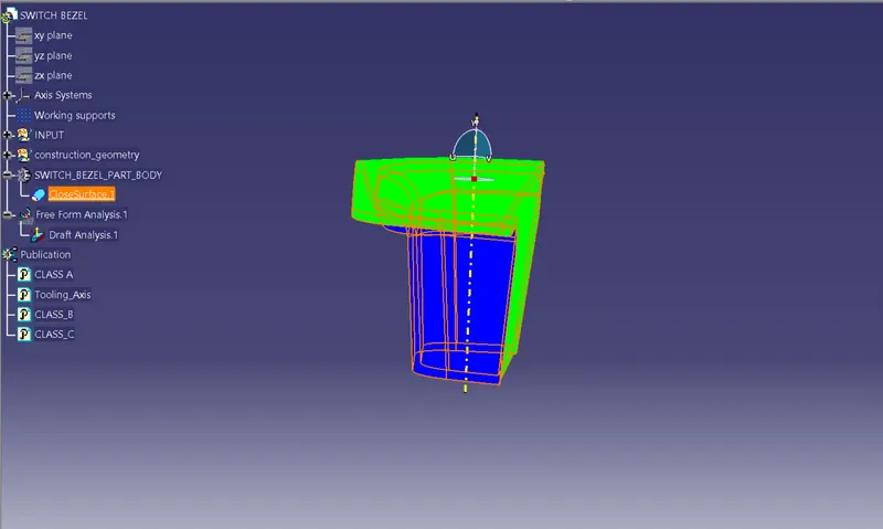
7.1 3D Part model in various orientations (Isometric, Front, Side, and Top View)
7.2 The expanded Tree Structure for the geometrical set and the Part Body
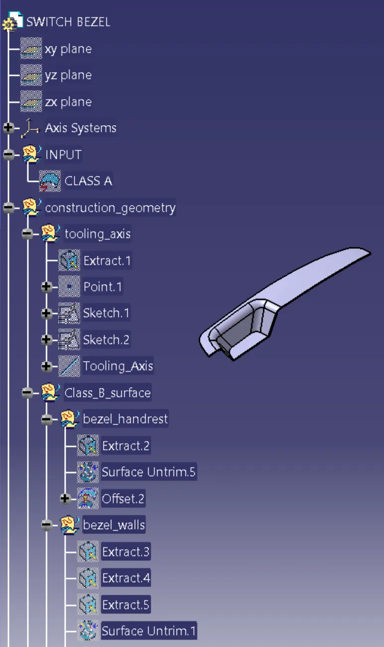
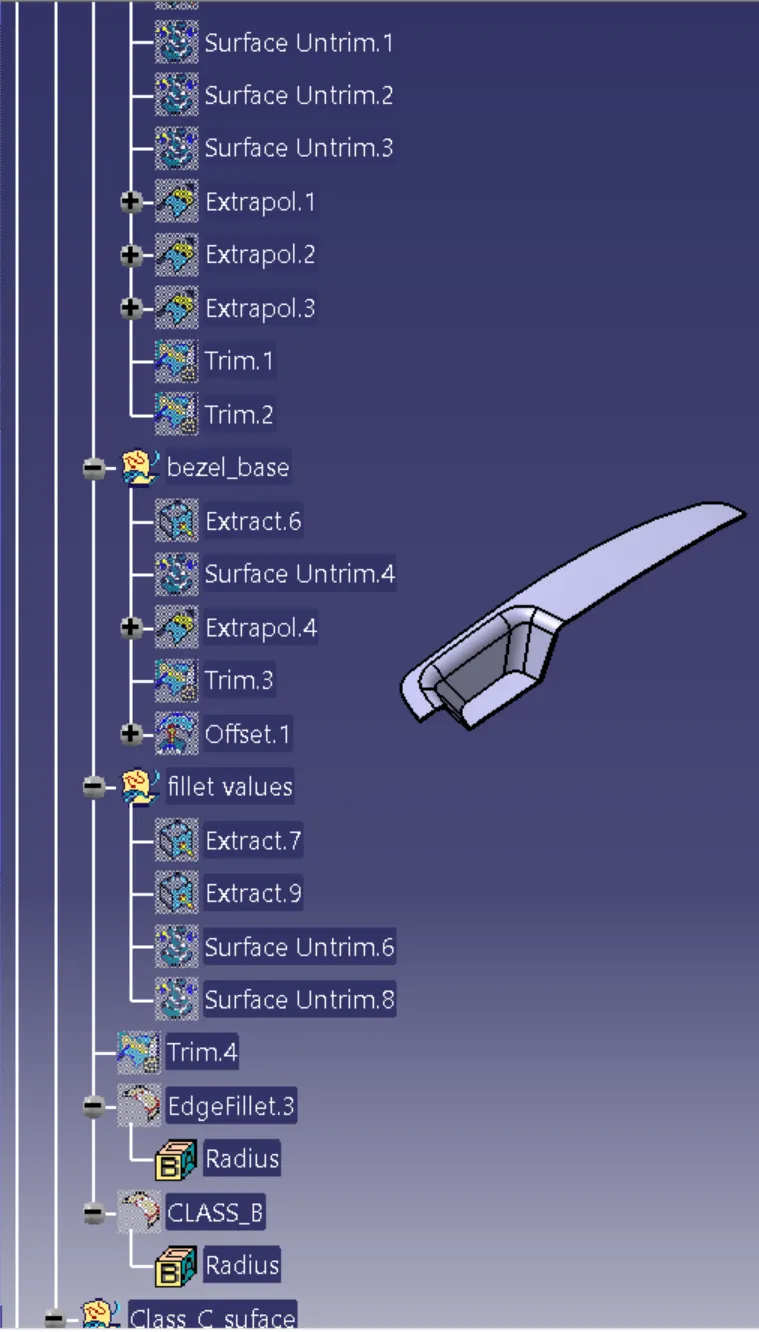
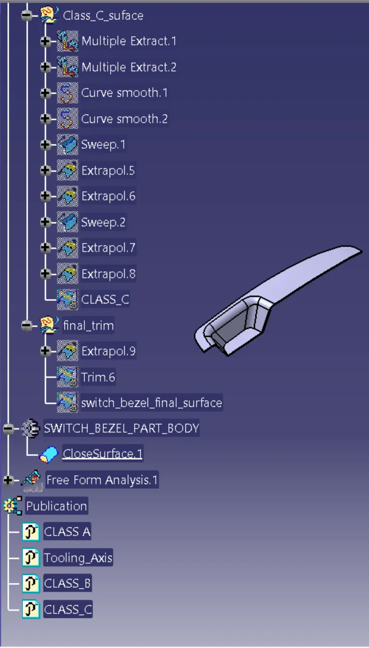
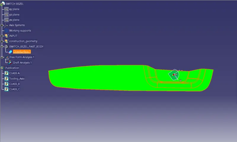
7.3 Draft analysis of the Final part body
Same procedure for the draft analysis of CLASS-A surface is followed.
- Change the view mode to material shading
- Align the Compass with Tooling axis.
- Lock the draft direction and perform the Draft analysis.
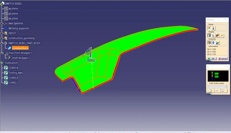
- The Draft analysis shows the Switch bezel Component is Feasible for manufacturing since it Cleared the Draft analysis.
Conclusion
I have successfully created the class-B and Class-C surfaces of Switch Bezel using the given Class-A surface along with the tooling axis in the CATIA surface workbench. And also created the final part body using the close surface command in the part design workbench and performed draft analysis for the same.