Week 8 - Challenge 6 - Core & Cavity Design
CORE & CAVITY DESIGN - CHALLENGE 6
AIM
To create the Core and cavity blocks for the switch bezel design.
INTRODUCTION
Switch Bezel
A switch bezel panel is nothing but a part which consists of the switch panels for the power windows and also has some place to rest the passenger’s hand on it. It is assembled on the main door trim panels.
Core and Cavity design
The Mould Core & Cavity are the shaped sections in either half of the mould tool which give the plastic product its final shape. The hot molten material is injected into the core & cavity and then sets hard into shape. The design of the core & cavity is essential in the correct formation of the product.
OBJECTIVE
- Perform the Draft analysis for the switch bezel part model
- Design core and cavity block for the switch bezel component.
Procedure for creating the tooling axis
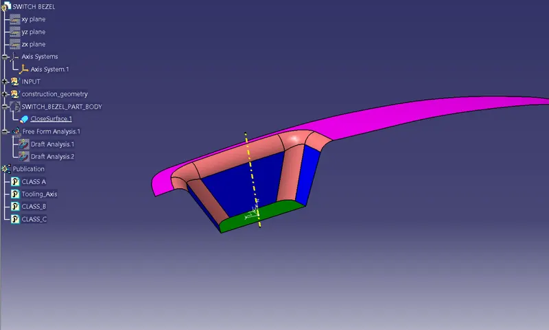
Tooling axis represents the opening and closing of the mold core and cavity during the manufacturing of the components.
- check the suitable direction for the tooling axis with the x, y and z directions.
- Using the given class-A surface, extract the base surface of the pocket and create a midpoint on the extracted surface.
- create an axis system with respect to the point created.
- By looking the A-surface, we can say the best tooling direction can be made along the z axis.
- Hence, we need to check whether all the faces of the walls clearing the tooling direction. For that,
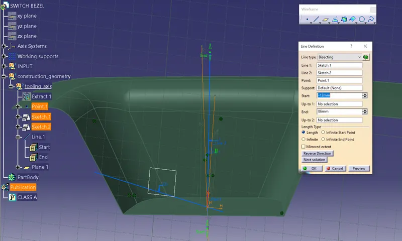
- create a positioned sketch on the y-z plane and using the project 3D element, project the wall faces on the y-z plane.
- Then create 2 lines and make it coincide with respective projected faces. And then with the lines created, a bisecting line can be made.
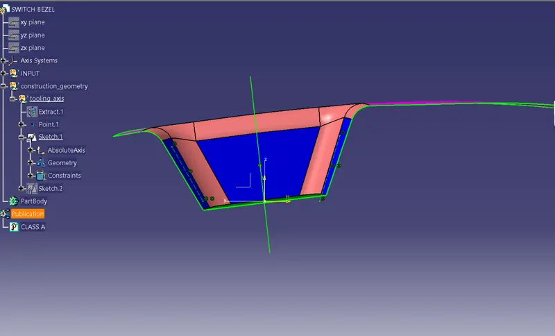
- Now considering the wall face on the x direction, create a sketch on the x-z plane and now we have face only on one side. Create an intersection or project the surface and create on line on it which coincide with wall.
- Now for the other wall create a line on the point we created earlier and make it at an angle 6 degree with the face.
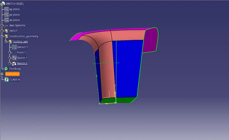
- By doing this procedure we get the second line for creating the Main Tooling axis.
Draft Analysis
Draft is a taper applied to the faces of the part that prevent them from being parallel to the motion of the mold opening. This keeps the part from being damaged due to the scraping as the part is ejected out of the mold.
The Draft Analysis allows the user to easily analyses the proper draft angle and manufacturability of the designed component.
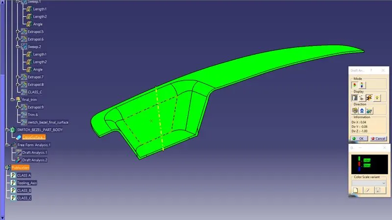
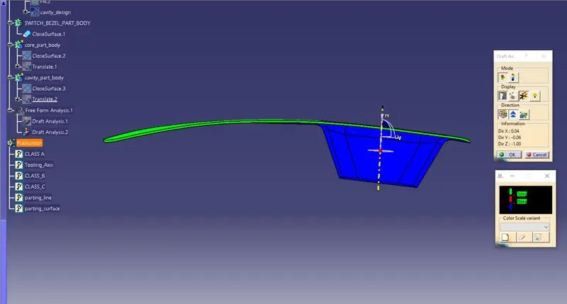
Draft analysis is done after determining the tooling axis, draft analysis is used to check whether the minimum draft (3 degrees) is maintained or not.
Procedure for performing the draft analysis are as follows
- Change the view mode of the component to be in customized parameter mode and then select the shading mode as materials.
- Then open the featured draft analysis tool from the insert menu.
- Then click on use the compass to define the current drafting direction and then drag and align the compass on the Tooling axis.
- Then lock the draft direction and perform draft analysis by clicking on the component.
- The green colour shows the positive daft tooling direction and the given surface passes the draft analysis.
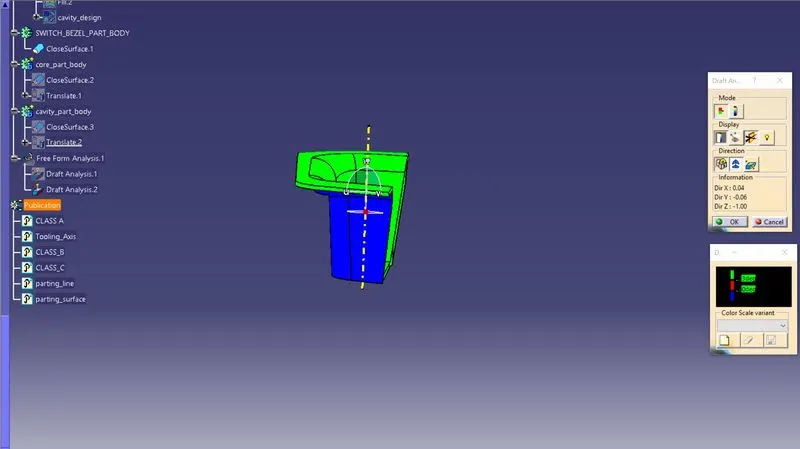
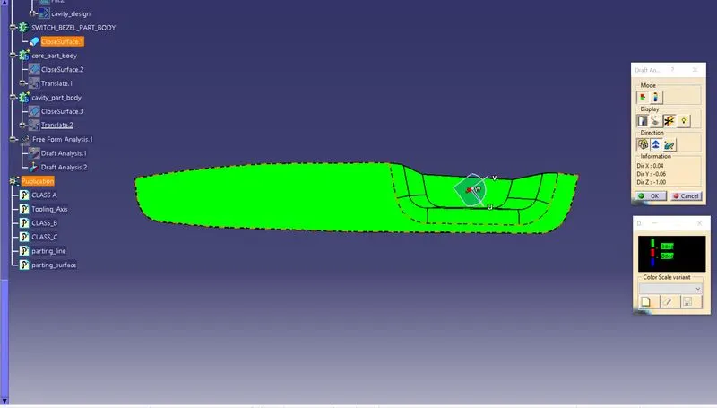
CORE BLOCK DESIGN
The design methodology for creating the core block are as follows
- Extract the class-A surface with some adequate value.
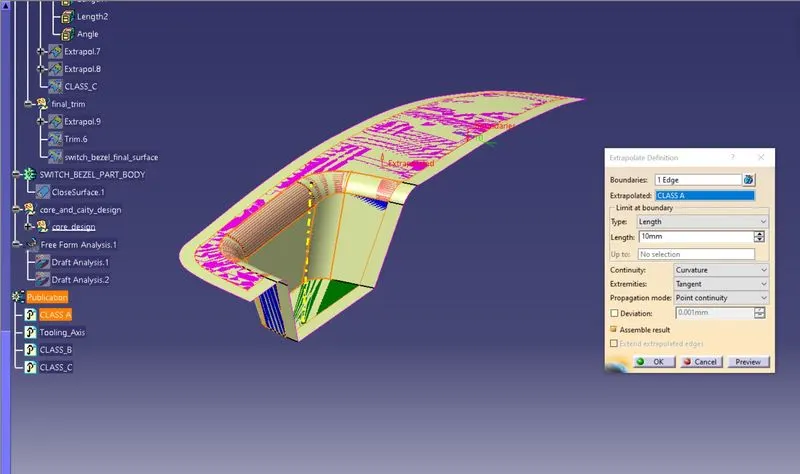
- Then trim the extrapolated surface using the class-C surface and then trim it with the class-B surface.
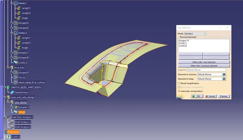
- Create a sketch with rectangular shape which should not exceed the trimmed surface created for core design.
- Extrude the sketch along the tooling axis and trim it with the other surface.
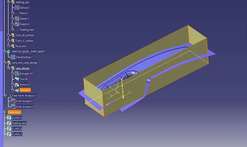
- Close the extruded surface using fill command and the final core block surface is created.
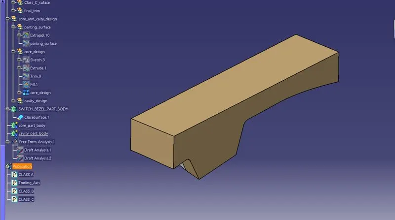
- In the part design workbench, create solid core block using the close surface feature.
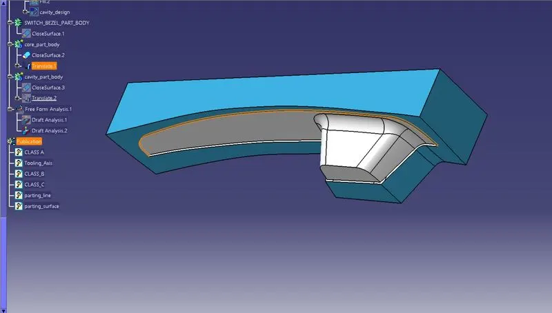
CAVITY BLOCK DESIGN
Same procedure for creating the core block is also followed here.
- First, Extrapolate the class-b surface.
- Extrude the sketch along the tooling axis direction.
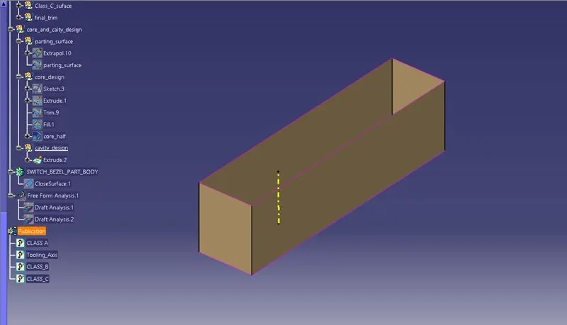
- Trim the extrude surface with the extrapolated class-B surface.
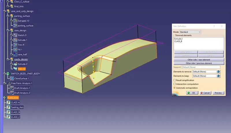
- Fill the other side of the surface using fill command.
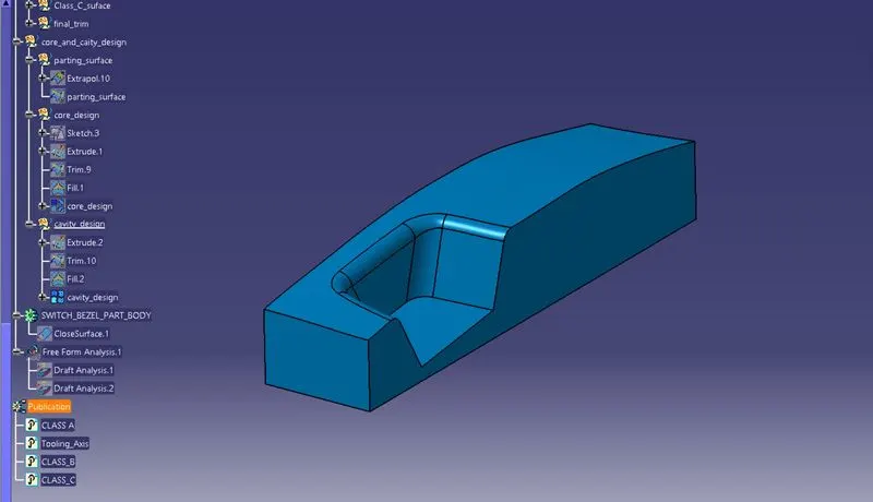
- Convert the final surface into solid body using close surface command in the part design workbench.
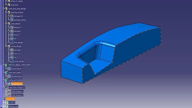
PARTING SURFACE
During the injection molding process, the core and cavity blocks are pressed tightly and form a sealed hollow mold cavity, the pressed surface is called the parting surface. In other words, it is a surface that separates the mold block into two parts – the core and the cavity. Usually parting surface are the biggest projection outline of the part.
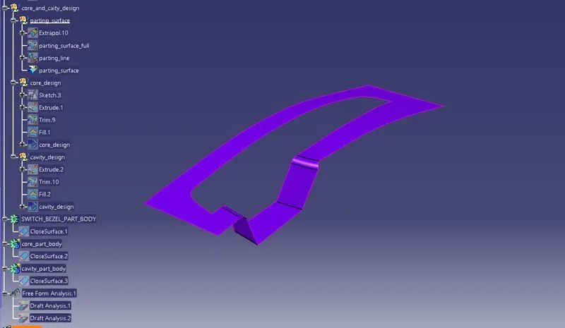
PARTING LINE
It is the junction between component and parting surface. Parting line should always lie on the B surface of the component.
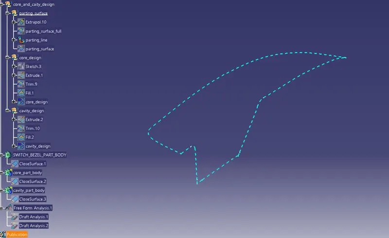
CORE and CAVITY part model in various orientations (Isometric, Front, Side, and Top View)
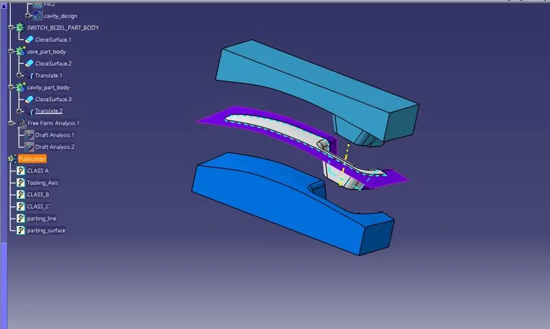
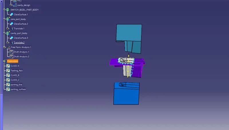
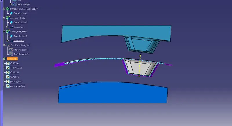
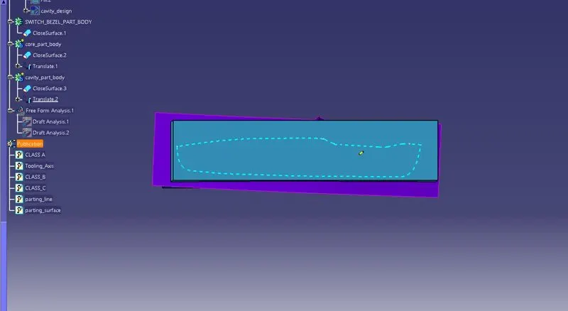
Section view
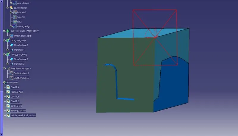
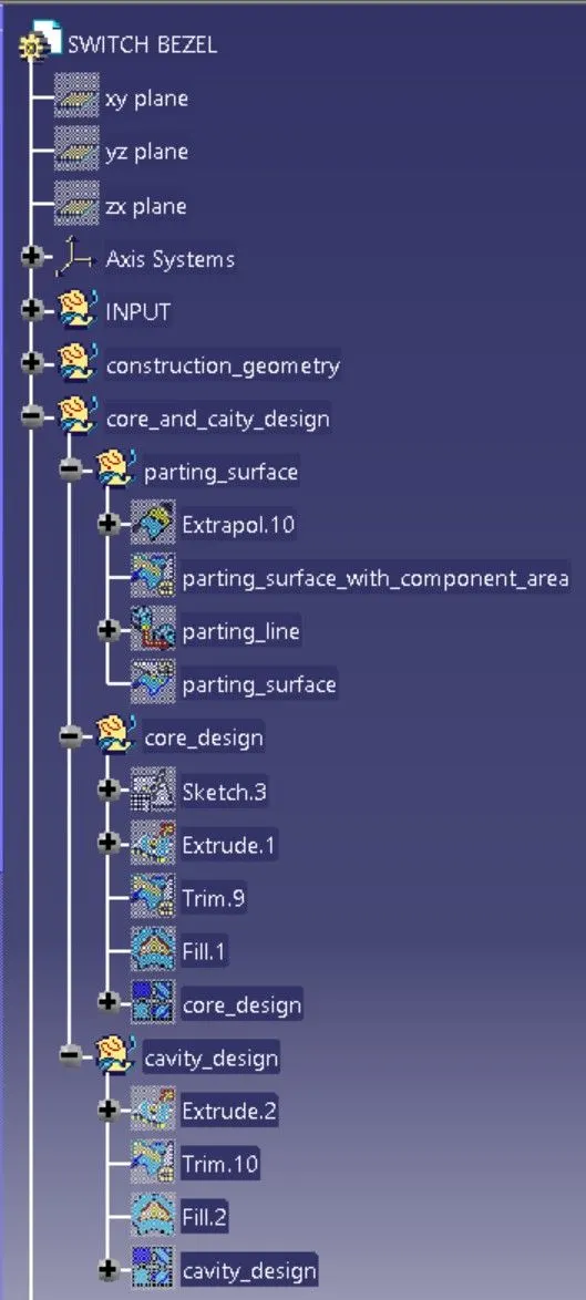
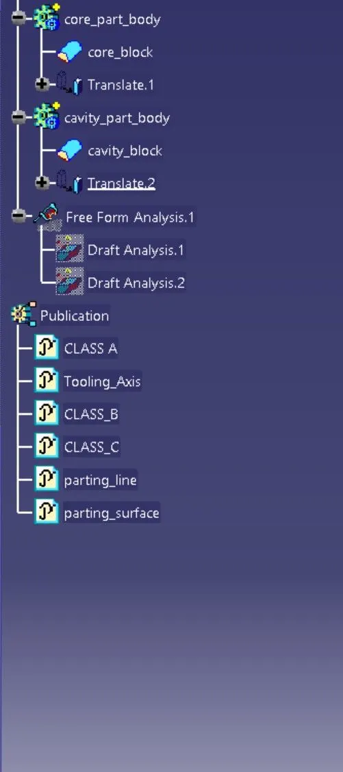
The expanded Tree Structure for the geometrical sets, part body and the publications