Wiring harness routing & packaging Rules Week 3 Challenge
Wiring harness routing & packaging Rules Week 3 Challenge
AIM
Define the mechanical components electrically and create COT tubes. Prepare the catalogue for the same.
INTRODUCTION
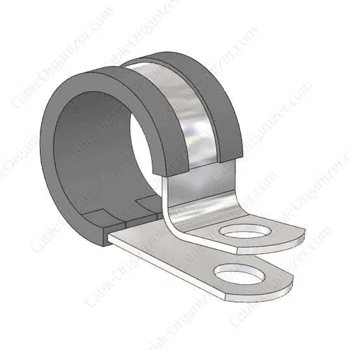
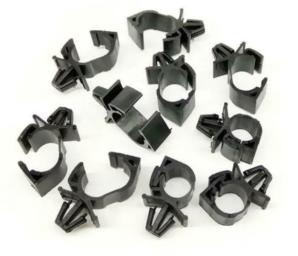
Cable clamps are accessories for wire and cable. They are used to bundle, clip, clamp, label, guide, and protect wires and cables. Clamps play an important role in the installation and maintenance of cable systems. Cable clamps are used in home construction, automotive, rigging, and many more industrial and manufacturing applications. The clamps are available in a wide variety of types and sizes.
The shape and size of the item or system being secured. The maximum diameter refers to the maximum diameter of the bundle of wires and cables. If the clamp is larger than the conduit foreign matter can enter the space between the two pieces can cause damage due to abrasion. If the conduit is larger than the clamp deformation and strain can occur on the mounting foot of the clamp and potentially break the clamp.
BACKSHELLS
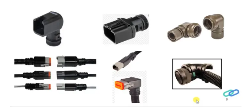
In general, connector back shells fall under the classification as ‘connector accessories. Back shells are the components that attach to the back of connectors often designed to guide the wires and cables that are terminated at the connector. The back shells are often mated with strain relief components, environmental seals, the shielding. The back shell may be made from metal or moulded using a rubber or neoprene covering over the back shell of the connector.
In other words, backshells are plastic moulded parts used at the wire entry side of the connectors either for protection or to improve the aesthetics/appearance of the harness. These are not mandatory parts of wiring harness and are always optional and driven by cost.
Corrugated tubes
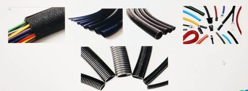
Corrugated tubes, convolutes, sleeves and many other types of coverings ae used to protect the wiring harness. Graphical representation of coverings is applied on bundles.
Corrugated conduits and protective hoses with various properties, from heat resistance through abrasion protection and impact strength to noise reduction, protect valuable cables against all unfavourable external influences.
OBJECTIVE
- Download the CAD data from the given source, create required geometrical parameters and define all the necessary electrical properties to the cad model.
- Download the back shell cad model from the given source and define it as electrical in the electrical part design workbench.
- Create the Corrugated tubes & add them to the Catalogue under the " Slit COT " family.
DESIGN METHODOLOGY
1. P-CLAMP
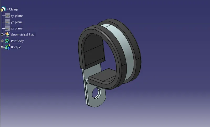
process:
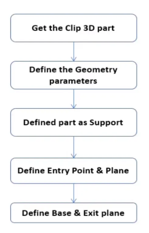
- From mechanical part design workbench create entry point and exit point for the p clamp
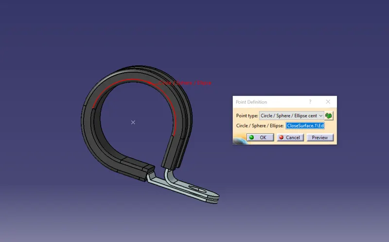
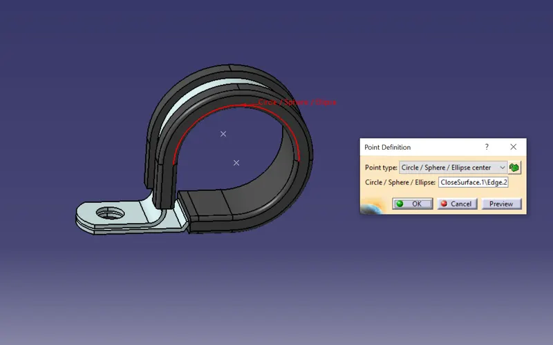
- create planes on the entry and exit points created and also create a base plane.
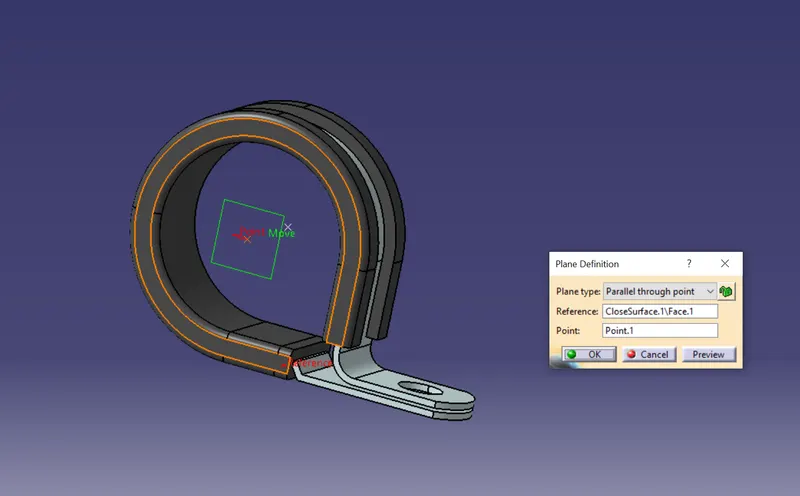
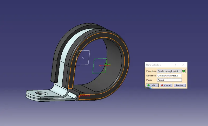
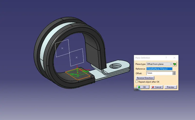
- Switch to Electric part design
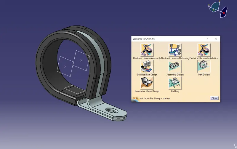
- Click on support definition on both sides - select part - select entry point - select entry plane, exit and base plane.
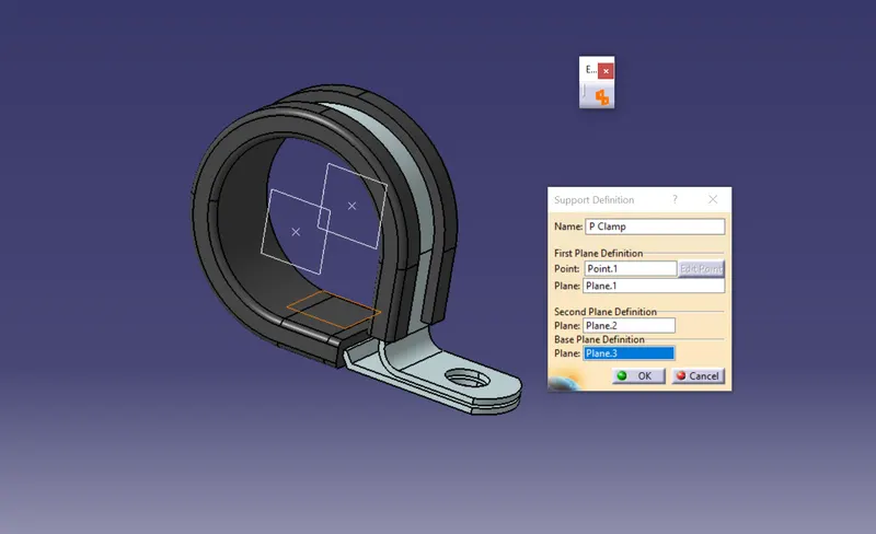
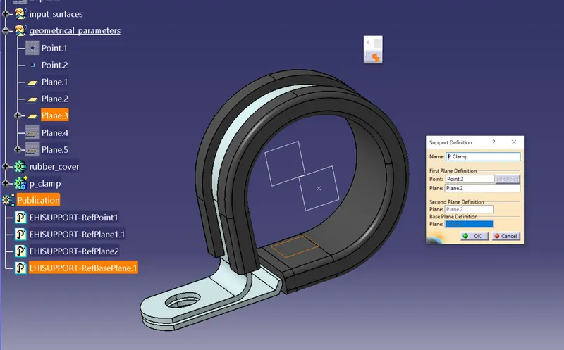
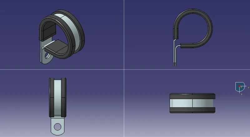
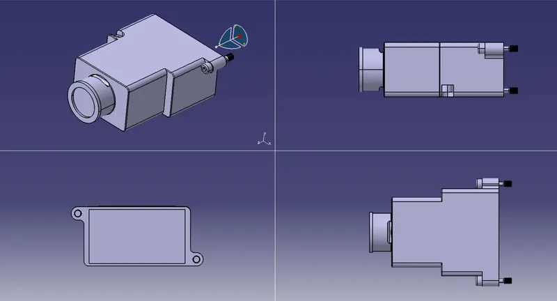
3D Part model in various orientations (Isometric, Front, Side, and Top View)
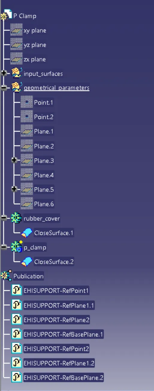
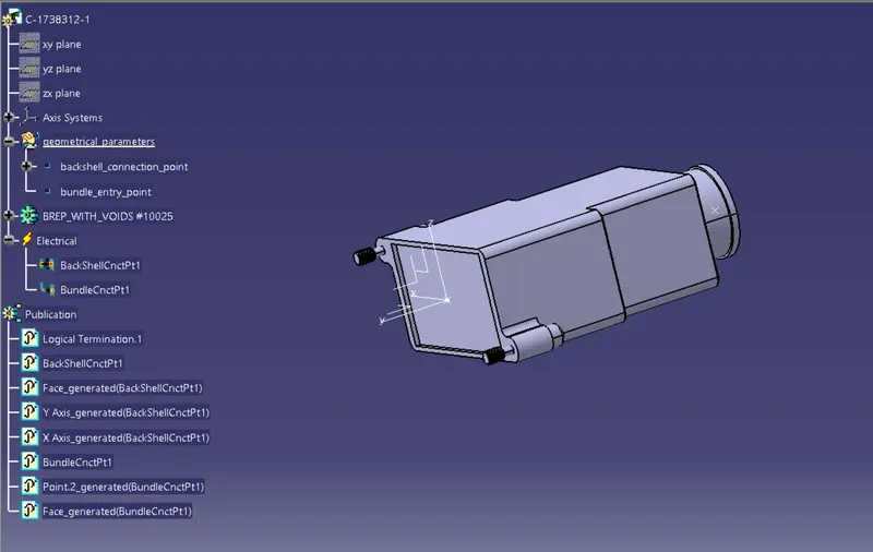
The expanded Tree Structure for the geometrical set and the Part Body
CATALOG document
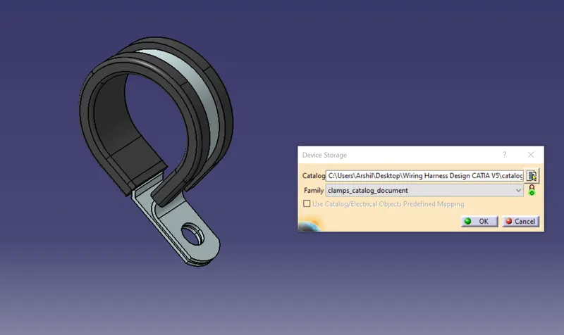
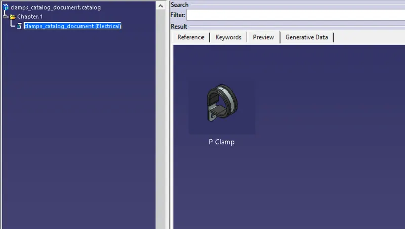
2. BACKSHELL
Process:
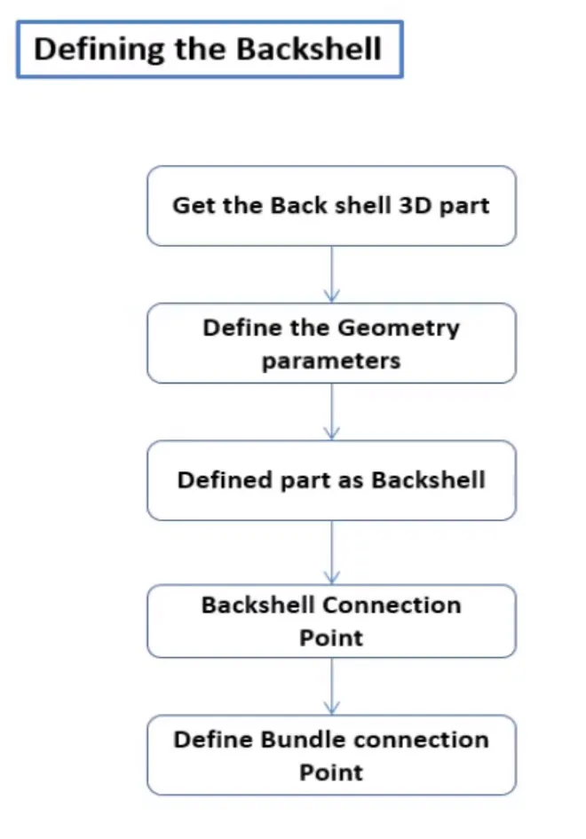
- create Back shell connecting point
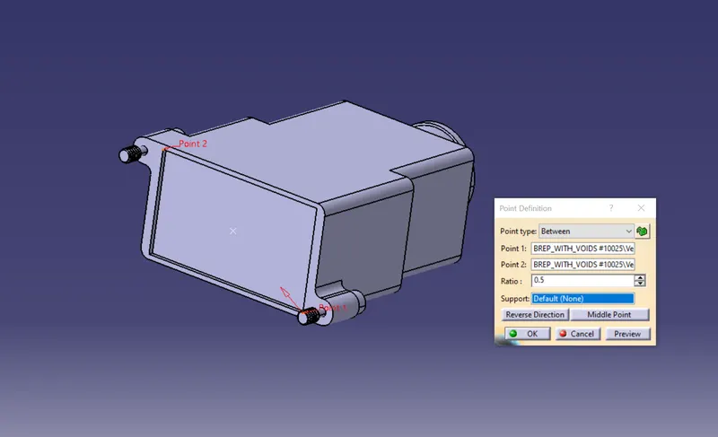
- create bundle connection point.
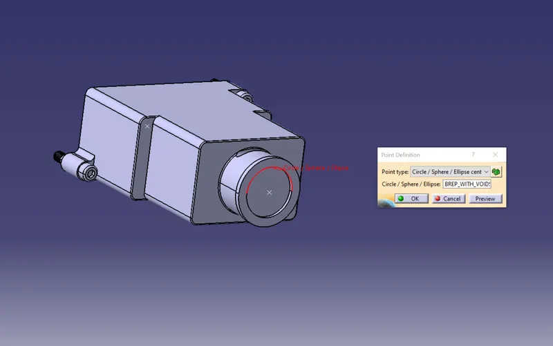
- create axis system for the back shell connection point
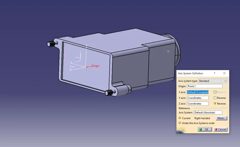
switch to Electrical part design.
- Apply electrical property to the part using define back shell command
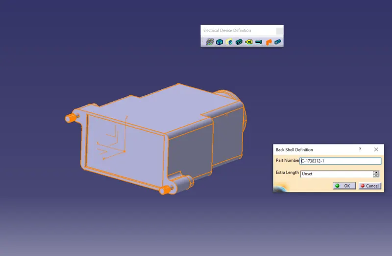
- Define Back shell connection point.
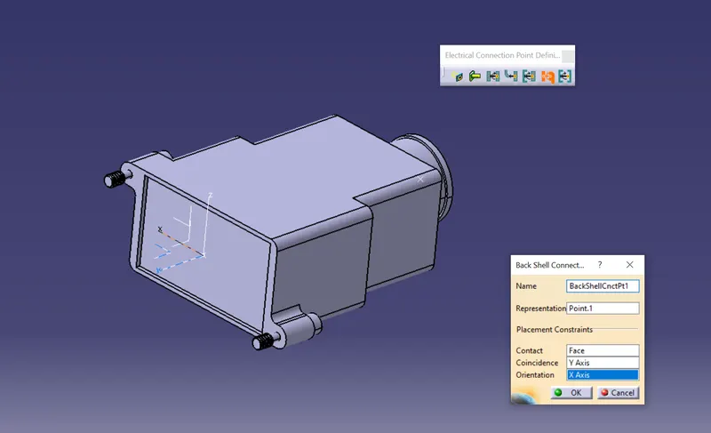
- Define bundle connection point.
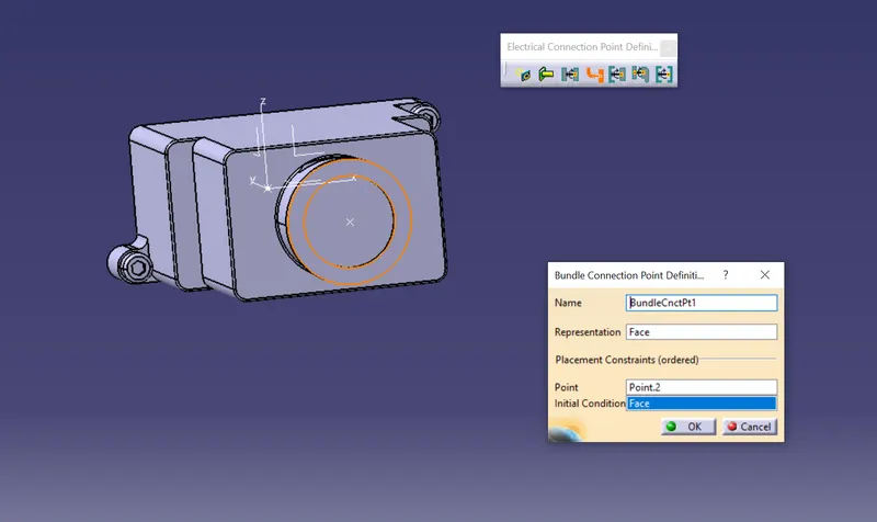
3D Part model in various orientations (Isometric, Front, Side, and Top View)
The expanded Tree Structure for the geometrical set and the Part Body
CATALOG
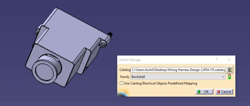
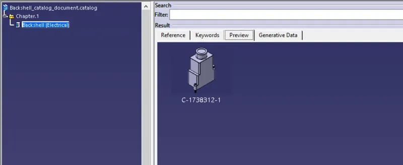
3. COT Tubes
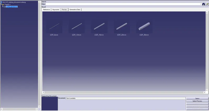
Create Following Corrugated tubes & add them in Catalogue under “Slit COT” family.
Process:
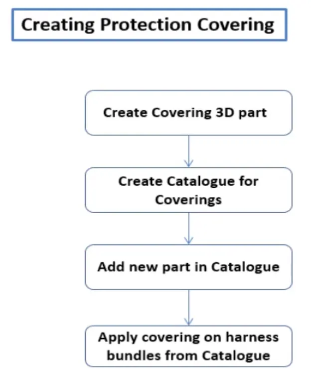
- Switch to Electrical part design
- Select Define protection Part
- Click on part on the design tree.
- Provide required dimensions to the create the part.
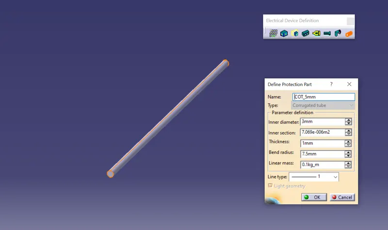
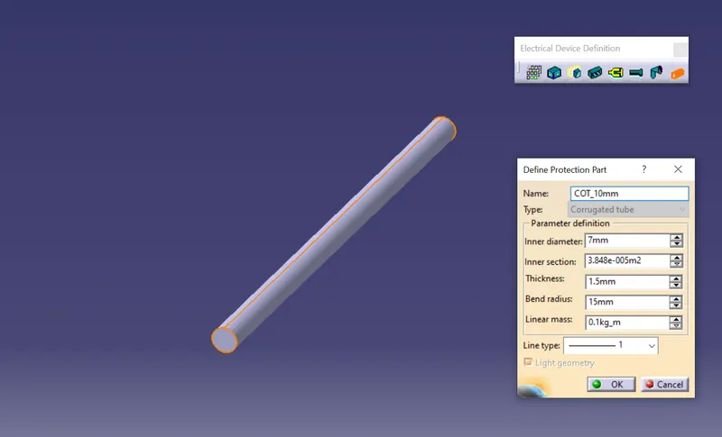
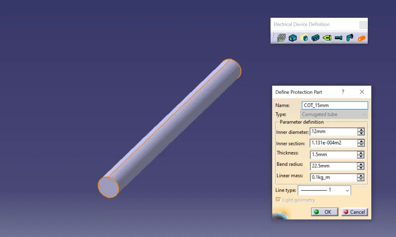
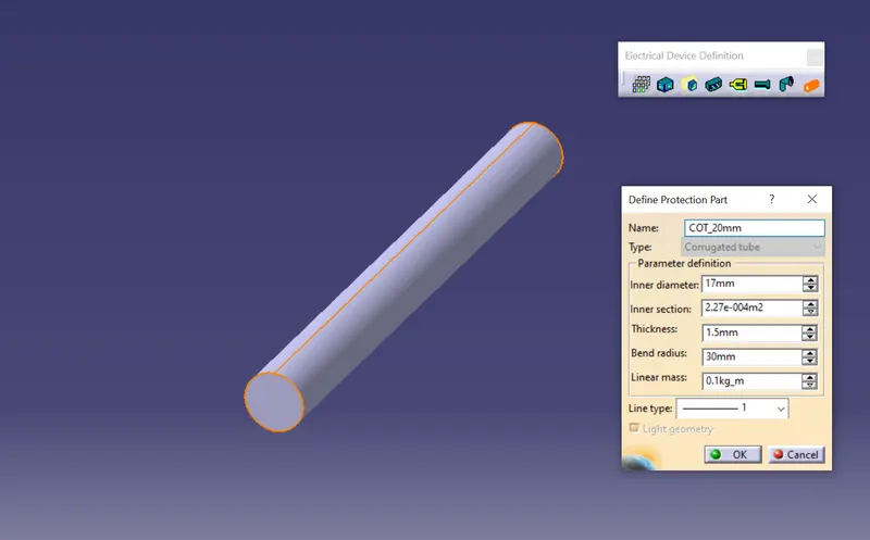
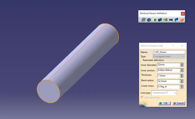
Catalogue under “Slit COT” family.
- created a new catalog document with name Slit_COT
- define family as conduit
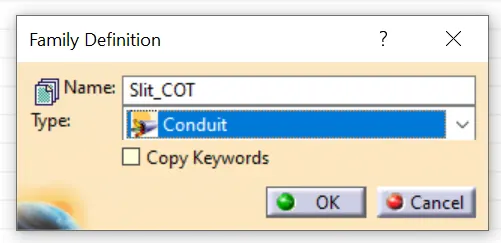
- added all the COT tubes into the catalog document
Conclusion
CAD parts have been successfully given electrical properties and COT tubes are created with required dimensions and also added every parts to respective catalog documents for future accessibility.