Fender Design - Wheel Arch Challenge
Fender Design - Wheel Arch
- Definition
- The wheel arc is an integrated part of a fender assembly. It is a semi-circular part which is positioned above the wheel of a vehicle. In some countries, it is also called as an inner fender.
- The most important body change was that the front wheel arch was cut higher into the fender. Its primary purpose is to prevent sand, mud, rocks, liquids, and other road spray from being thrown into the air by the rotating tyre which in terms protects the passenger cabin of the car as well as the pedestrians on the road from these types of thrown particles by rotating tyres.
For every region there are different standards and regulations follows for fender design. They are,
- Japanese Standard
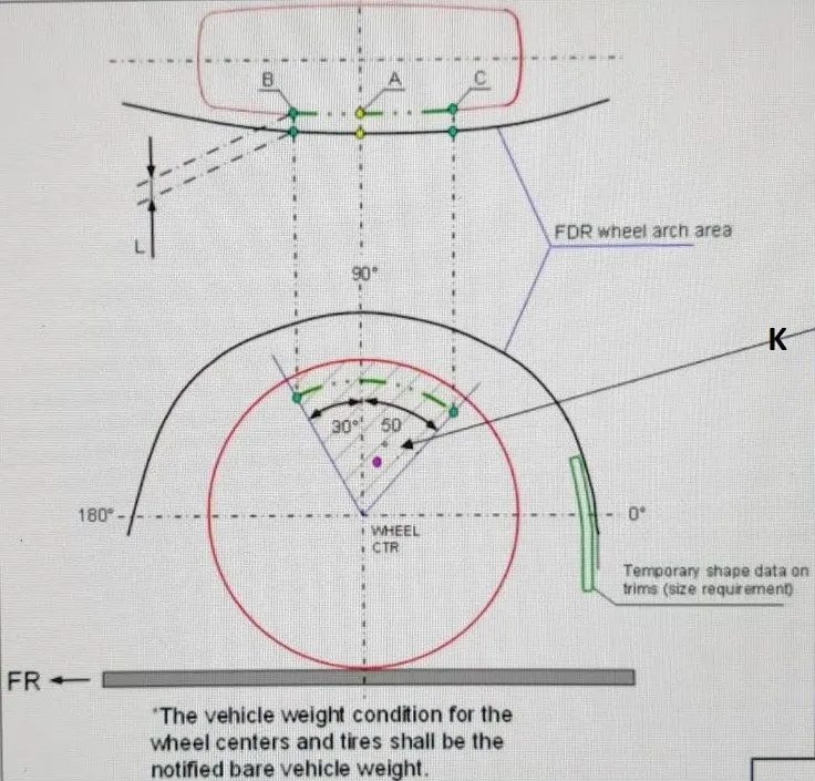
- Measure clearance L of tyre, hub, cap and fender in three different positions with area K and produce clearance check chart to validate.
- Clearance must be greater than 5 mm in all the three positions.
- Wheel guard requirement: The value of ‘a’ shall be more than 5 mm at a line 30 degree forward and 50 degrees backward from the central vertical axis of wheel.
- American Standard
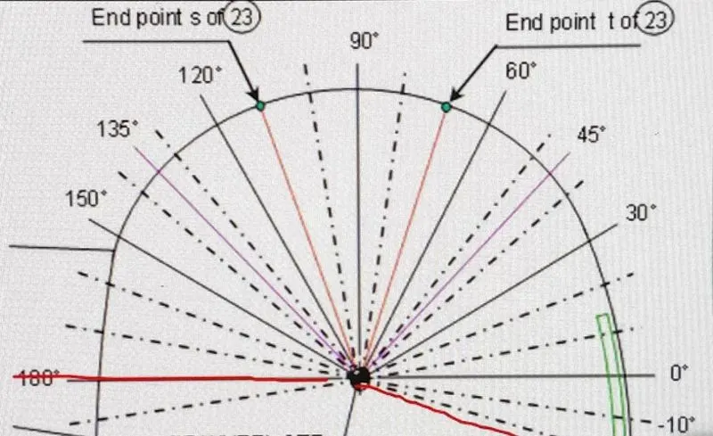
- Make clearance check details on all positions from -100 degree to 100 degree and make the clearance check chart.
- All values should be greater than 5 mm to satisfy the regulations.
- The value of ‘a’ shall be more than 5 mm at a line 30 degree forward and 50-degree rearward from the central vertical axis of wheel.
- European Standard
- Objective of Wheel arch challenge
To calculate the Wheel Arch gap at required points based on the European regulations and check whether the given wheel arch of the car passes the European standard.
- European Standards for the Wheel Arch design
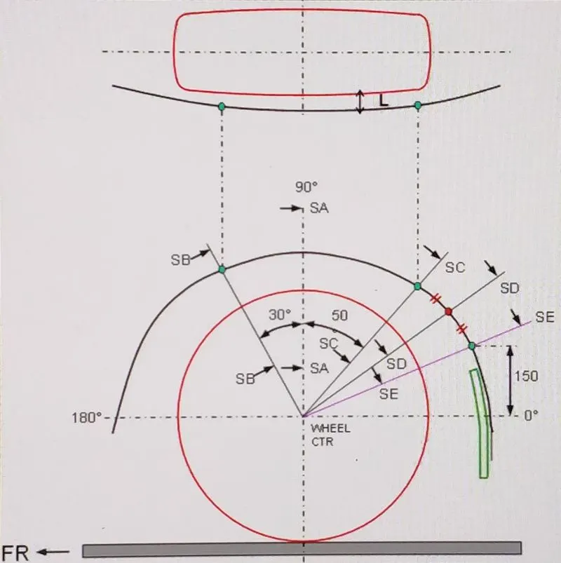
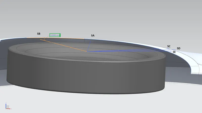
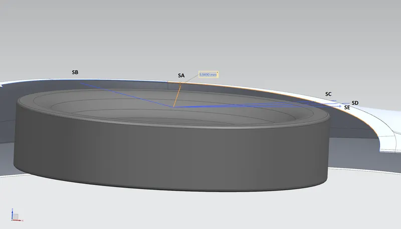
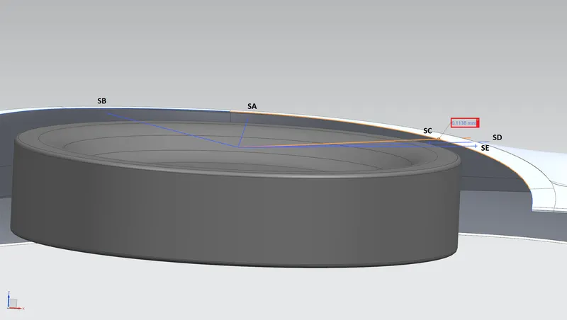
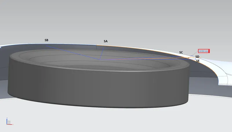
- As per the European standards, the clearance “L” at sections SB, SA, SC, SD and SE should be more than 10mm to pass. Analys the clearance value and produce CL check chart to validate.
- Wheel Guard Requirements- The value of “a” shall be more than 5 mm at a line 30-degree forward and 50-degree rearward from the central vertical axis of wheel.
4.Procedure to find the values using NX CAD
- Create a datum plane on the outermost face of the tyre and required sketch on it.
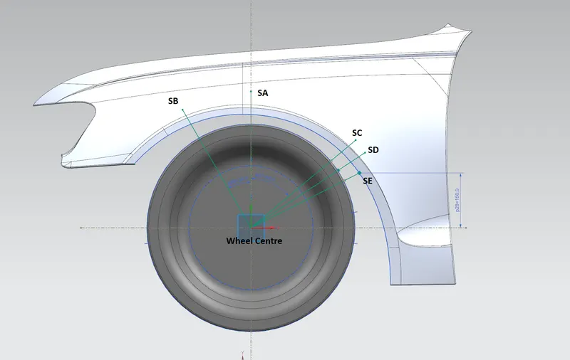
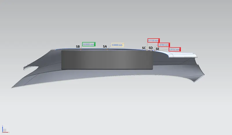
- The L value at the section SB is calculated as 10.0000 mm
- The L value at the section SA is calculated as 9.9490 mm
- The L value at the section SC is calculated as -0.1138 mm
- The L value at the section SD is calculated as -2.8784 mm
- The L value at the section SE is calculated as -5.9752 mm
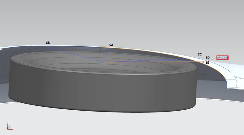
Measurements achieved at sections SB, SA, SC, SD and SE are as follows

Clearance “a” Check, sketch is drawn between the fender wheel arch and tyre at sections SB and SC respectively and measured the value for both.
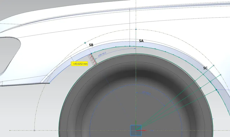
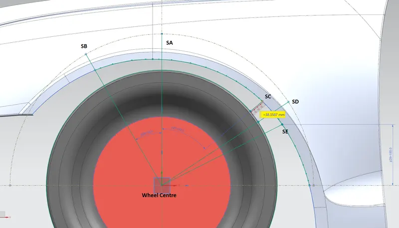
Clearance “a” Value obtained are as follows

Conclusion
From the values measured, it is clear that the given fender wheel arch model failed to satisfy European standards at sections SA, SC, SD and SE.