Week-11 Challenge: Braking
Aim: - To understand the concepts of Braking in Electric Vehicle with the Help of MATLAB & Simulink.
Objective: -
- For a defined driving cycle, calculate the energy required for braking.
- Why electric motor can’t develop braking torque at high speed similar to starting? How electric and mechanical brakes are coordinated?
- Make a MATLAB program which plots contour of given motor speed, torque and efficiency values. Attach the code as a .m file attach a screenshot of all the plots.
Introduction to Braking in Vehicles: -
Most brakes use friction on the two sides of the wheel, the collective press on the wheel converts the kinetic energy of the moving object into heat. For example, regenerative braking turns much of the energy to electrical energy, which may be stored for later use. Eddy current brakes use magnetic fields to turn kinetic energy into electrical current in the brake disc, blade, or rail, which is converted into heat.
The following are the most common types of braking systems in modern cars.
Hydraulic braking system:
This system runs on brake fluid, cylinders, and friction. By creating pressure within, glycol ethers or diethylene glycol forces the brake pads to stop the wheels from moving.
• The force generated in the hydraulic braking system is higher when compared to the mechanical braking system.
• The hydraulic braking system considered as one of the important braking systems for modern vehicles.
• The chance of brake failure is very less in case of the hydraulic braking system. The direct connection between the actuator and the brake disc or drum makes very less chance of brake failure.
Electromagnetic braking system:
Electromagnetic braking systems can be found in many modern and hybrid vehicles. The electromagnetic braking system uses the principle of electromagnetism to achieve frictionless braking. This serves to increase the life span and reliability of brakes. Also, traditional braking systems are prone to slipping while this is backed with the quick magnetic brakes. So without friction or need of lubrication, this technology is preferred in hybrids. Also, it is quite modest in size compared to the traditional braking systems. It is mostly used in the trams and trains.
To make electromagnetic brakes work, a magnetic flux when passed in a direction perpendicular to the rotating direction of the wheel, we see rapid current flowing in a direction opposite to the rotation of the wheel. This creates an opposing force to the wheel rotation and it slows down the wheel.
Servo braking system:
Also known as vacuum or vacuum-assisted braking. Among this system, the pressure applied to the pedal by the driver is increased.
They use the vacuum that is produced in petrol engines by the air intake system in the engine's intake pipe or via a vacuum pump in diesel engines.
A brake where power assistance is used to reduce the human effort. In a car, engine vacuum is often used to make a large diaphragm flex and operate the control cylinder.
• Servo braking system boosters used with the hydraulic brake system. The size of the cylinder and the wheels are practically employed. Vacuum boosters increase the braking force.
• Pushing the brake pedal releases the vacuum on the side of the booster. The difference in the air pressure pushes the diaphragm for braking the wheel.
Mechanical braking system:
The mechanical braking system powers the hand brake or emergency brake. It is the type of braking system in which the brake force applied on the brake pedal is carried to the final brake drum or disc rotor by the various mechanical linkages like cylindrical rods, fulcrums, springs etc. In order to stop the vehicle.
Mechanical brakes were used in several old automobile vehicles but they are archaic nowadays due to their less effectiveness.
Regenerative braking:
Regenerative braking is an energy recovery mechanism that slows down a moving vehicle or object by converting its kinetic energy into a form that can be either used immediately or stored until needed. In this mechanism, the electric traction motor uses the vehicle's momentum to recover energy that would otherwise be lost to the brake discs as heat. This contrasts with conventional braking systems, where the excess kinetic energy is converted to unwanted and wasted heat due to friction in the brakes, or with dynamic brakes, where the energy is recovered by using electric motors as generators but is immediately dissipated as heat in resistors. In addition to improving the overall efficiency of the vehicle, regeneration can significantly extend the life of the braking system as the mechanical parts will not wear out very quickly.
Types of Brakes:
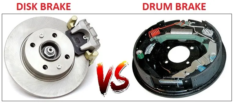
DISC BRAKE
The disc brake is a mechanism for slowing or stopping the rotation of a wheel from its motion. A disc brake is normally made of cast iron, but in some cases, it is also made of composites such as carbon-carbon or ceramic -matrix composites. This is linked to the wheel and/or the axle. To stop the wheel, friction material in the form of brake pads is forced against both sides of the disc. Friction caused, on the disc wheel will slow or stop.
DRUM BRAKES
A drum brake is a traditional break in which the friction is caused by a set of shoes or pads that press against a rotating drum-shaped part called a brake drum.
The term \"drum brake\" usually means a brake in which shoes press on the inner surface of the drum. Where the drum is pinched between two shoes, similar to a standard disk brake , it is sometimes called a \"pinch drum brake\", although such brakes are relatively rare.
1. Calculating the energy required for braking For a defined driving cycle:-
Driving Cycle:
A driving cycle is a series of data points representing the speed of a vehicle versus time.
Driving cycles are produced by different countries and organizations to assess the performance of vehicles in various ways, as for instance fuel consumption, electric vehicle autonomy and polluting emissions. Fuel consumption and emission tests are performed on chassis dynamometers. Tailpipe emissions are collected and measured to indicate the performance of the vehicle.
Another use for driving cycles is in vehicle simulations. More specifically, they are used in propulsion system simulations to predict performance of internal combustion engines, transmissions, electric drive systems, batteries, fuel cell systems, and similar components. Some driving cycles are derived theoretically, as it is preferred in the European Union, whereas others are direct measurements of a driving pattern deemed representative.
There are two types of driving cycles:
- Transient driving cycles involve many changes, representing the constant speed changes typical of on-road driving.
- Modal driving cycles involve protracted periods at constant speeds.
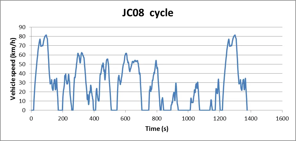
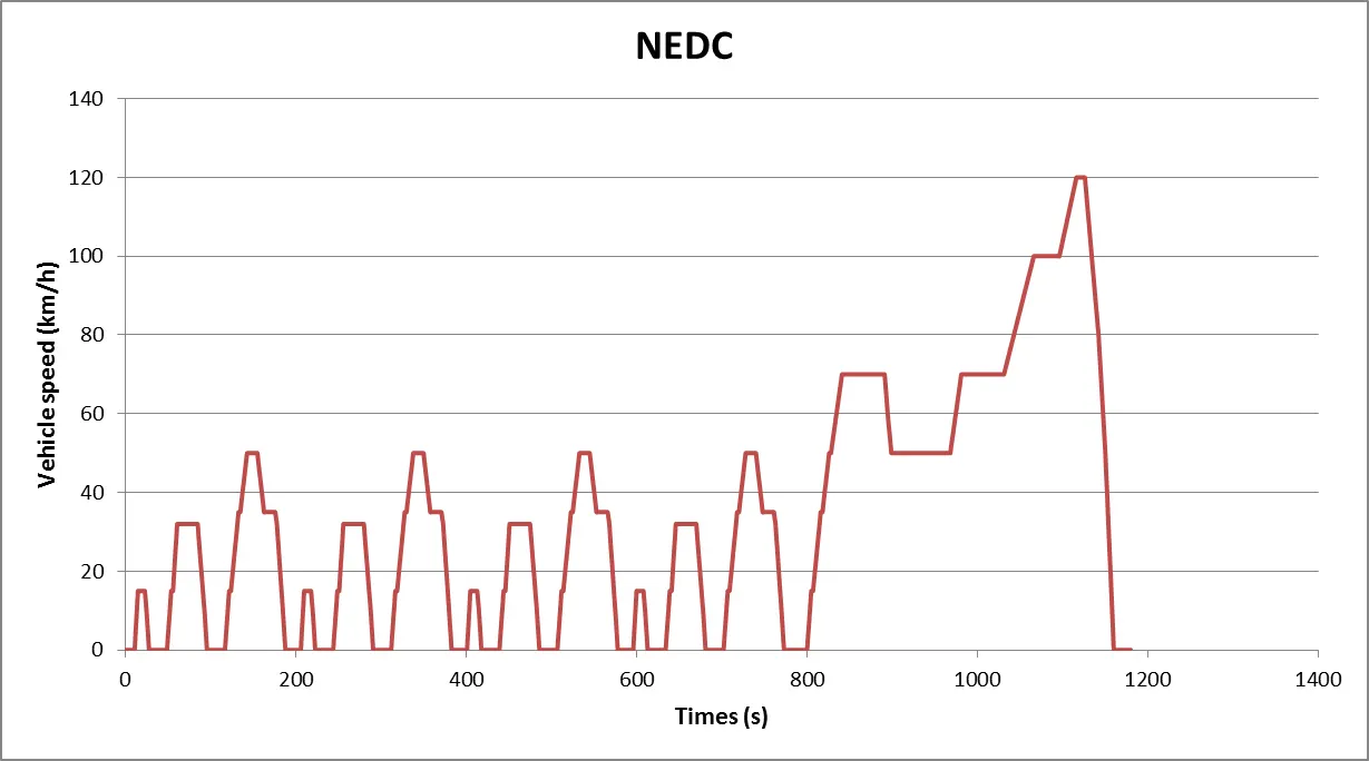
The American FTP-75, and the unofficial European Hyzem driving cycles are transient, whereas the Japanes 10-15 Mode and JC08 cycles are modal cycles. Some highly stylized modal driving cycles such as obsolete European NEDC were designed to fit a particular requirement but bear little relation to real world driving patterns. On the contrary, the current WLTP is striving to mimic real word driving behavior. The most common driving cycles are probably the WLTC, NEDC, SORDS and the FTP-75, the later corresponding to urban driving conditions solely. Driving cycle design is the core technology for these standard cycles. Drive cycle recognition is applying to Hybrid Electric Vehicle.
Some of driving Cycle is shown below.
For Braking, friction consumes some energy.The kinetic Energy for breaking can be represented as follows
Breaking Energy (E )= 1/2 mv2 Joules
Where
m = Total mass of the vehicle in Kg
= vehicle mass + pay load
v = (Initial velocity- final velocity) in m/s
Let us consider the total mass of vehicle (m) = 1000kg
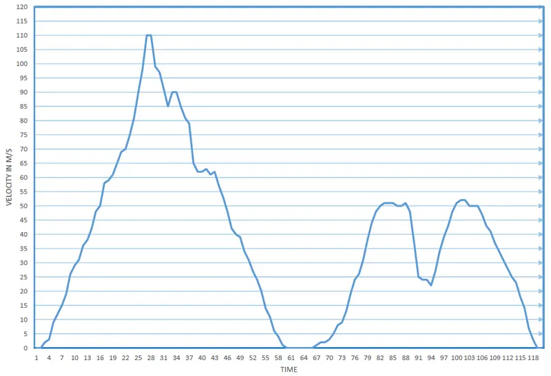
The initial velocity at time(T)=25 is 90m/s
The final velocity at time (T) = 60 is 0m/s
Therefore the energy required for braking a vehicle is
E = 0.5*1000*90^2
= 4050 KJ
Drive cycle:-
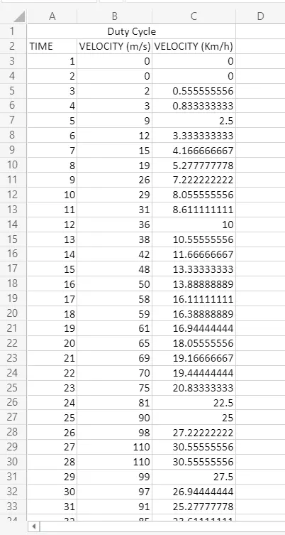
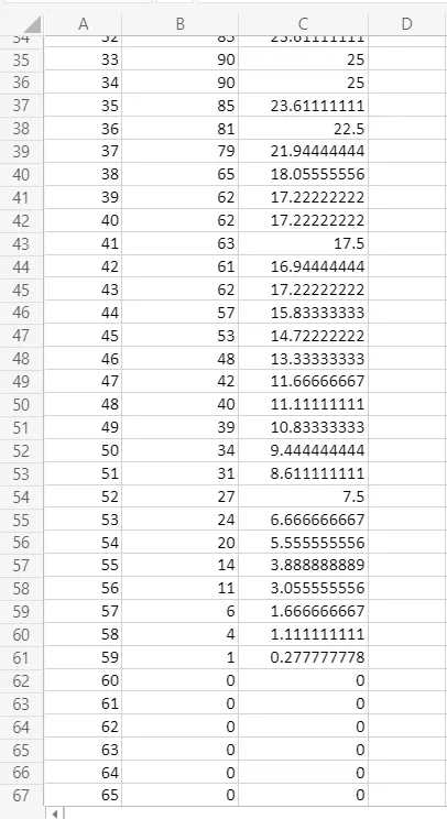
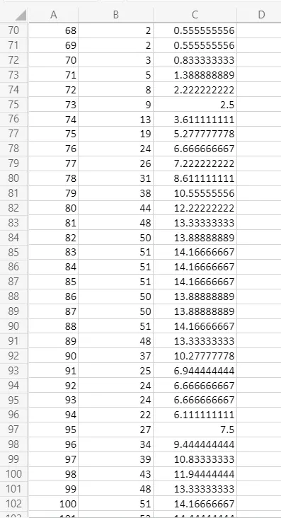
A drive cycle with a time duration of 120sec is created in microsoft excel is shown below.
Link:- https://drive.google.com/file/d/1G90y7SIkN2SgrlZW6-ZUMtP_1Svk2-9H/view?usp=sharing
2) Electric motor can’t develop braking torque at high speed similar to starting:-
The below figure 2.1 represents a two quadrent operation of the Induction machine. In first quadrant both speed and torque are positive (+ve) it is called forward motoring mode. In second quadrant speed is positive(+ve) and torque is negitive (-ve) it is called Braking mode.
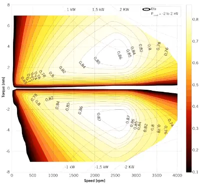
figure 2.1
Electrical motor uses regenerative braking which develops counter torque to stop the Electric vehicle.In Regenerative braking the motor itself act as generator so the efficiency as a generator is less than motor. During the starting of Electric vehicle it draws large amount of current and produces large amount of torque. As the motor speed (rpm) increases the current drawn by the vehicle decreases then the torque will gradually decreased. During regenerative braking torque has to be reversed and vehicle speed has to be drecrased to zero this takes some time. since The accelearation torque generated by the motor is always greater than the decelaration torque generated by generator.
Coordination of Electric and Mechanical Brakes :-
There are basically two ways to coordinate the brakes
1) series braking
2) parallel braking
1) series braking:- In this braking, regenerative and mechanical brakes are applied one after the another.
2)parallel braking:- Both the brakes are applied parallel way. The efficiency of the braking is improved using Electric driven intelligent Brake (EDIB) developed by Nissan leaf as shown in figure 2.2
case1:-
When the vehicle is moving at low speed then more amount of regenerative braking is applied and less amount of frictional (mechanical) brakes are applied.
case2:-
When the vehicle is moving at high speed then both are applied heavily but as vehicle speed decrease the amount of frictional (mechanical) brakes starts to decrease.
figure 2.2
3) MATLAB program which plots contour of given motor speed, torque and efficiency values:-
Link:- https://drive.google.com/file/d/1rPbSQ7-rLECx51R6-JHR56KJ_0OgmHV7/view?usp=sharing
MATLAB Script:-
clear all
close all
clc

%plotting a contour of a motor with speed, torque & efficiency values
x=linspace(1,1000); % Speed in rad/s
y=linspace(1,250);  % Torque in N-m

%entering the values of motor loss constants
Kc = 0.21;     % copper loss constant
Ki = 0.008;    % iron loss constant
Kw = 0.00001;  % winding loss constant
ConL = 20;     % Motor loss constant

%creating a mesh
[X,Y] = meshgrid(x,y);
Outputpower =(X.*Y);  %Torque x Speed = power

B=(Y.^2)*Kc;   % Copper loss
C= X*Ki;       %Iron loss
D=(X.^3)*Kw;   % windage loss
Inputpower =Outputpower + B + C + D + ConL;
Z = Outputpower ./ Inputpower;

%Setting the efficiencies for which contour shold be plotted
V=[0.60,0.75,0.90,0.91,0.925,0.94,0.95,0.955];
box off
grid off
contour(X,Y,Z,V);

xlabel('Speed in rad/s');
ylabel('Torque in N-m');
hold on
Discription:-
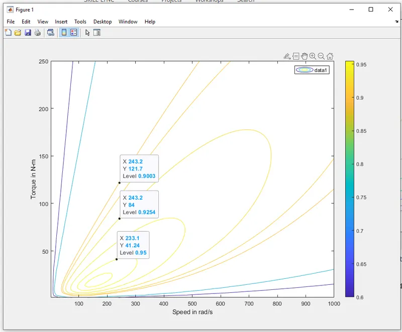
In the above MATLAB Script the range of speed is 0 to 1000 in x-axis and Torque is 0 to 250 in y-axis with the help of array called linspace.
For calculating the efficiency, various losses and their constants are to be determined
efficiency (η ) = Output power/Input power
for a motor
Input power = output power +copper loss+Iron loss +windage loss
copper loss = I2*R=Kc*T2
Iron loss = Ki*w
windage loss = Kw*w3
Plot:-
Conclusion:-
Contours provide high efficient areas for a given motor. From the plot we are able find best efficiency for a required torque.
for example:- three points are selected at constant speed , If the motor is going to run at 40 N-m then the efficiency is 95% .