Project 2 Thermal modeling of battery pack
Aim:-Thermal modeling of a battery pack
Objective: - For a 10 cell series lithium ion battery model, simulate the thermal effects and compare life cycle performance at various temperatures, charge & discharge rates using MATLAB.
Simulink Model:-
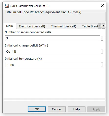
Here, I have Created a lithium ion battery model consisting of 10 cells connected in series groups, 1st group has 6 cells in series, 2nd group has only one cell and 3rd group has three cells in series.
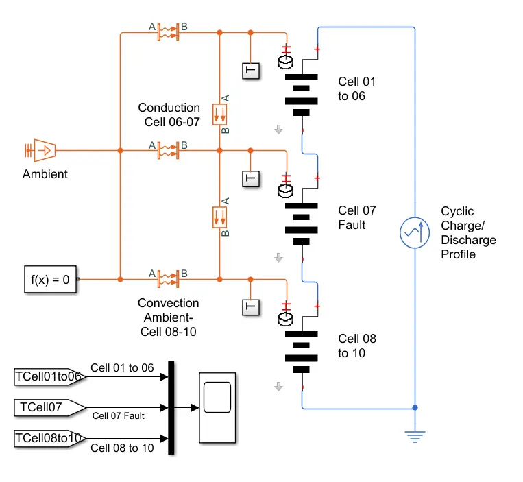
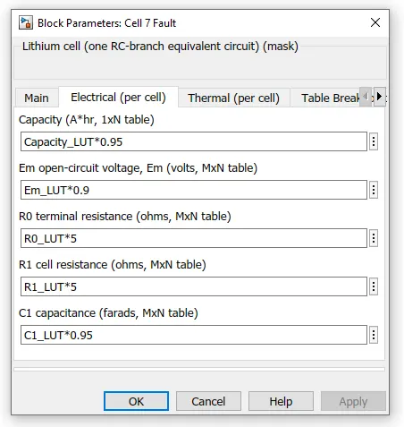
It shows how to simulate a battery pack consisting of multiple series-connected cells in an efficient manner. It also shows how a fault can be introduced into one of the cells to see the impact on battery performance and cell temperatures. For efficiency, identical series-connected cells are not just simply modeled by connecting cell models in series. Instead a single cell is used, and the terminal voltage scaled up by the number of cells. The fault is represented by changing the parameters for the Cell 07 Fault subsystem, reducing both capacity and open-circuit voltage, and increasing the resistance values.
Subsystem of Battery Pack:-
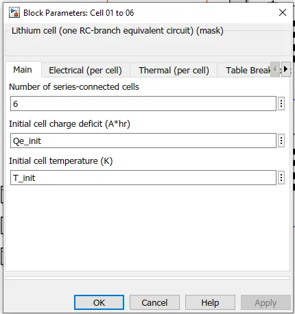
a)Cell 01 to 06
The cell Subsystem basically consist of a thermal subsystem with 1RC lithium cell which calculate the temperature and thermal effect of the cell and PS gain block which multiplies input physical signal by constant y=U*gain.Here the current- voltage source represents ideal voltage source that is powerfull enough to maintain the specified voltage at its output regardless of the current passing through it. The output voltage is V=Vs where Vs is the numeric value represented at the physical signal port.
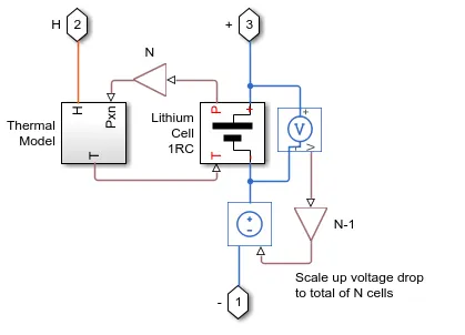
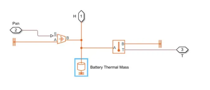
Thermal Model:- It is the sub system of the cell and its simulink blocks are shown below.
Lithium 1RC Subsystem:-
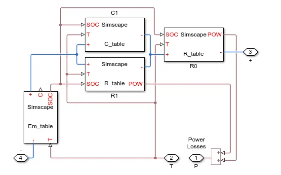
This block basically consist of a capacitor (C) value which depends on external physical SOC and Temperature
(T). Here 'Em' represents cells main branch voltage source and determines values for SOC and capacity.Also resistance value in 'R- Table' represents the external physical signal input SOC and T.
Test case 1:- Without SOC Calculation
Model 1:-
Blocks used in the model:-
- AC Source
- Lithium cells
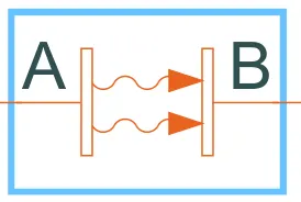
- Convective heat transfer
- Conduction heat transfer
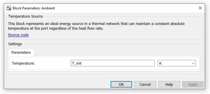
- Temperature Source (Ambient)
- Temperature Sensor
- Thermal reference
- Electrical reference
- Commonly used blocks such as add, gain, solver configuration, Display, Constant, PS-Simulink converter, Simulink-PS converter, go to tag and from tag.
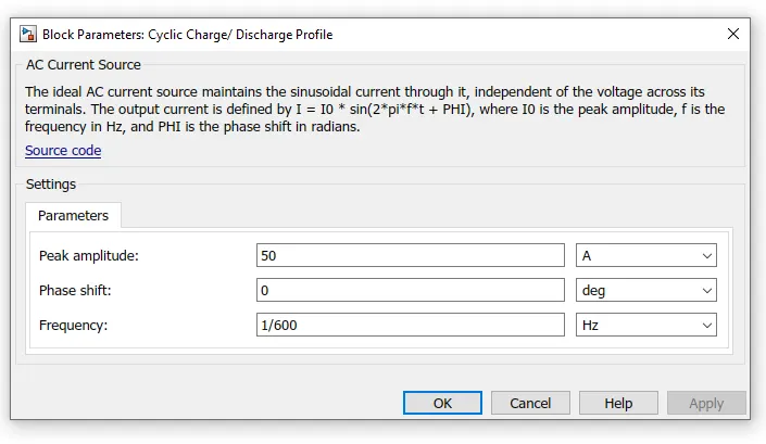
- AC Source:-
2.Lithium cells
a) cell 01 to 06
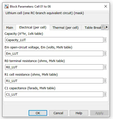
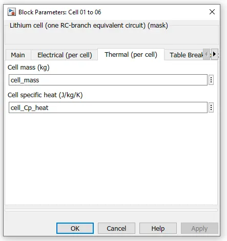
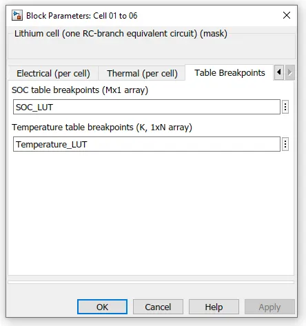
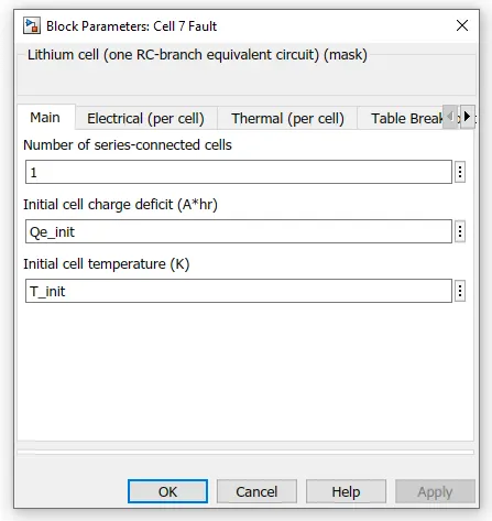
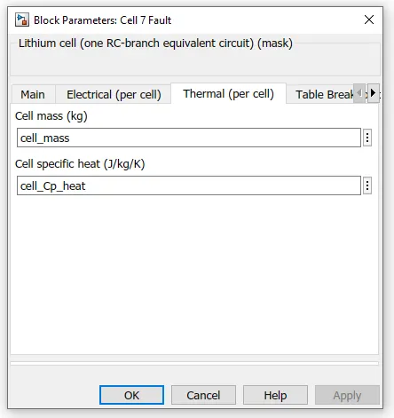
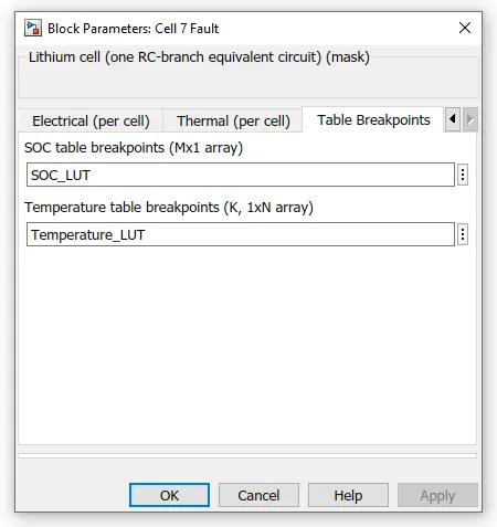
b) cell 07
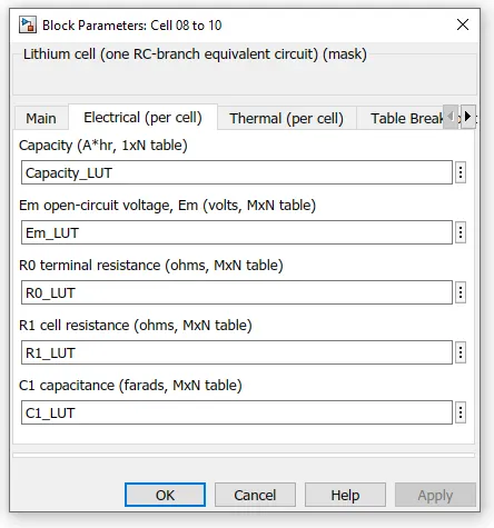
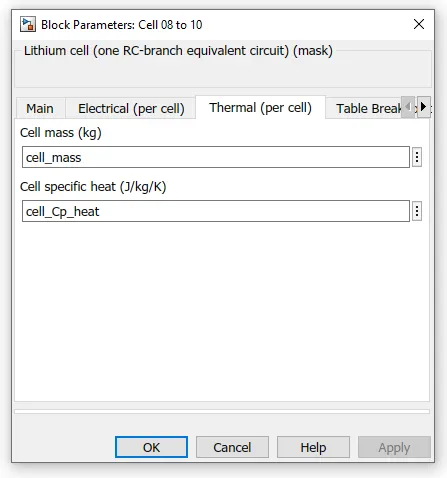
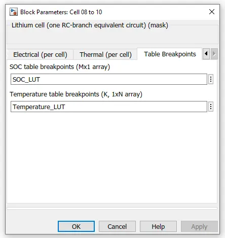
c) cell 08 to 10
3.Convective heat transfer:-
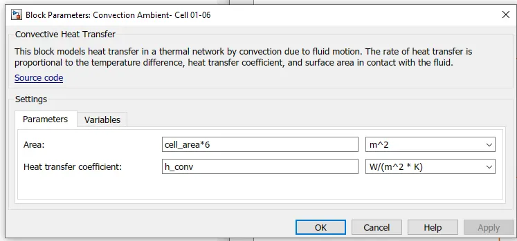
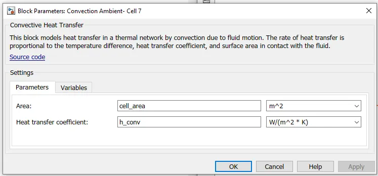
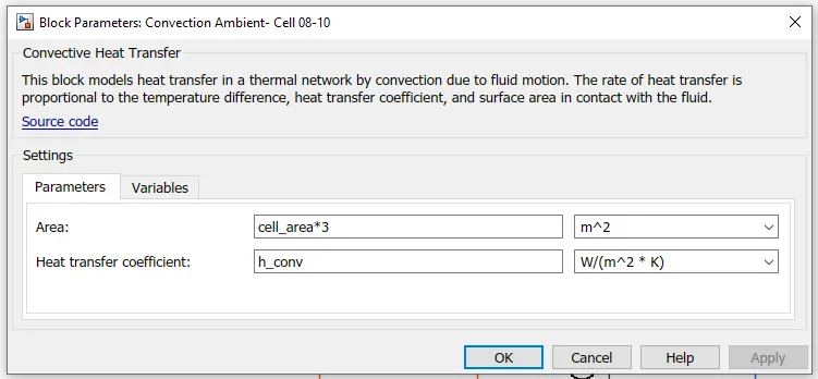
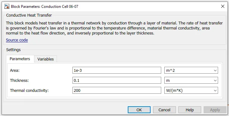
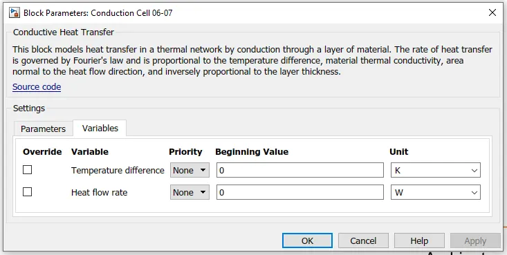
4.Conduction heat transfer
The simulink block is shown below.
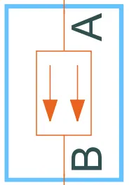
Note:-Hete the block parameters for conduction sell 07-08 is similar to conduction cell 06-07.
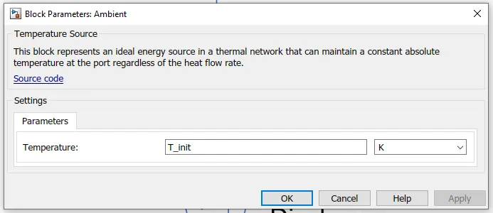
5. Temperature source

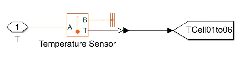
Subsystem T :-

This subsystem basically consist of a Temperature sensor, thermal reference, PS simulink converter and Goto.
6.Temperature Sensor
This block measures temperature in a thermal network. There is no heat flow through the sensor. The physical signal port T reports the temperature difference across the sensor. The measurement is positive when the temperature at port A is greater than the temperature at port B.
7.Thermal reference

This block represents a reference point in a thermal network where the temperature is equal to absolute zero.
8. Electrical Reference

Electrical reference port. A model must contain at least one electrical reference port (electrical ground).
9.Commonly used blocks
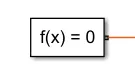
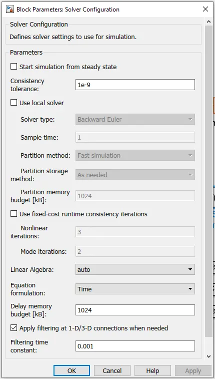
a)Solver configuration:-
b) From:-

It Receive signals from the Goto block with the specified tag. If the tag is defined as 'scoped' in the Goto block, then a Goto Tag Visibility block must be used to define the visibility of the tag. After 'Update Diagram', the block icon displays the selected tag name (local tags are enclosed in brackets, [], and scoped tag names are enclosed in braces, {}).
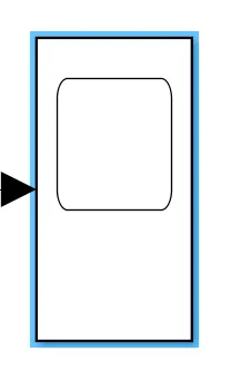
c) Scope:-
It basically used to display the output in a graphical manner.
d)MUX
the inputs and outputs for the MUX should be Multiplex scalar or vector signals.

e)PS-Simulink Converter:-
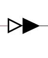
It Converts the input Physical Signal to a Simulink output signal.The unit expression in 'Output signal unit' parameter must match or be commensurate with the unit of the Physical Signal and determines the conversion from the Physical Signal to the Simulink output signal.
Workspace Details:-
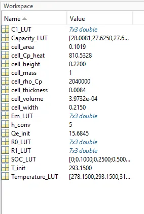
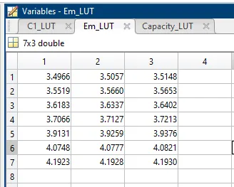
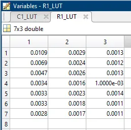
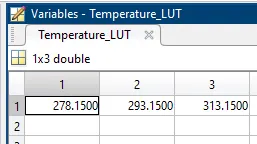
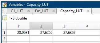
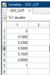
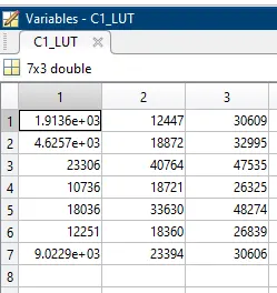
Results:-
Conclusion:-
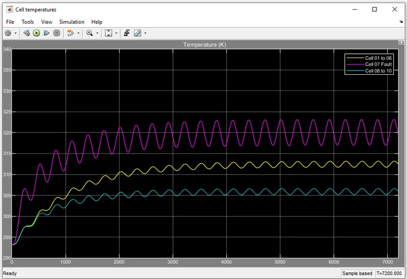
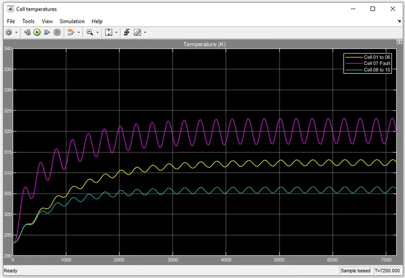
- Due to fault in the battery pack cells from 01 to 06, 07 and 08 to 10 are operating at different temperatures.
- From the graph we can observe that cell 01 to 06 are operating at a temperature of of 313K (40°C) and cell 08 to 10 are operating at 303K (30°C).
- while the cell 07 which is having a fault is showing a maximum temperature of 323.5K (50°C).
- So, a cell which is under a faullt condition will have a higher temperature and it will eventually damage the battery pack.
TEST CASE 2: With SOC Calculation
Model 2:-
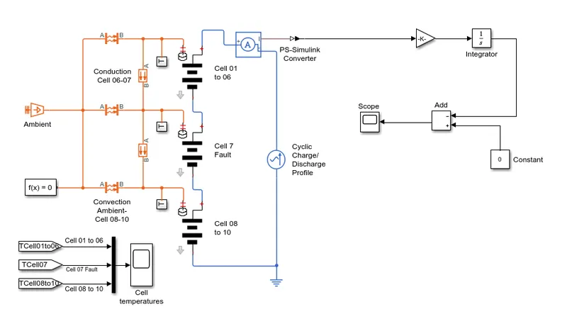
Discription:-
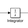
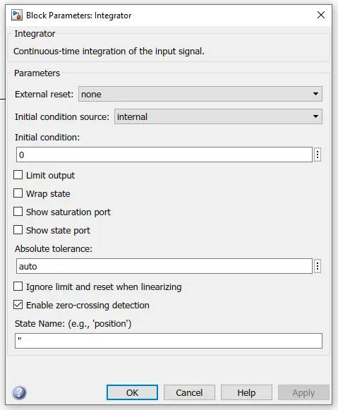
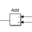
Here in order to get SOC, I have used a current sensor to get the current in Ampere which is later converted into a simulink signal by using a PS-Simulink converter then I have converted to Ah using a gain block. The Ah value is then integrated to get SOC.Remain that all the blocks and their parameters remain same as model 1.
Blocks Used :-
1) Gain
2)integrator
3)Add
4) Constant
Note:- Except the block 1 to 4 used, remaining All the blocks and there values are similar to the Model 1.
1) Gain

It basically does Element-wise gain (y = K.*u) or matrix gain (y = K*u or y = u*K).
2)integrator
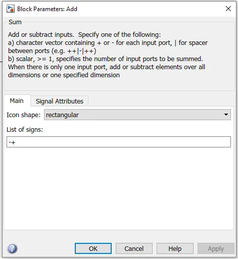
3)Add
4) Constant
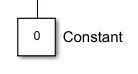
Output the constant specified by the 'Constant value' parameter. If 'Constant value' is a vector and 'Interpret vector parameters as 1-D' is on, treat the constant value as a 1-D array. Otherwise, output a matrix with the same dimensions as the constant value.
Results:-
Conclusion:-
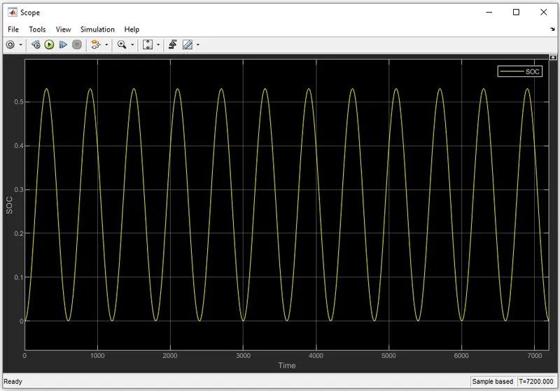
- The SOC is varied in between 0 to 52% and its charging and discharging occurs at a duration of 600 Seconds.
- For 7200 seconds the battery pack is charged and discharged for 12 times.
- from results we can observe that fault cell temperature is highest compare to the remaining cells in battery pack.