Project-1: Powertrain for aircraft in runways
Aim: - Powertrain for aircraft in runways
Objective: -
Part A:
1. Search and list out the total weight of various types of aircrafts.
2. Is there any difference between ground speed and air speed?
3. Why is it not recommended to use aircraft engine power to move it on the ground at Airport?
4. How an aircraft is pushed to runway when its ready to take off?
5. Learn about take off power, tyre design, rolling resistance, tyre pressure, brake forces when landing.
Part B:
6. A. With necessary assumptions, calculate the force and power required to push / pull an aircraft by a towing vehicle.
B. Develop the model for the calculated force and power using Simulink.
7. A. Design an electric powertrain with type of motor, it’s power rating, and energy requirement to fulfill aircraft towing application in Simulink. Estimate the duty cycle range to control the aircraft speed from zero to highest. Make all required assumptions. Prepare a table of assumed parameters. Draw a block diagram of powertrain.
(Hint :DC7 Block)
B. Also, Design the parameters in excel sheet.
Part A:-
1)Introduction: -
An aircraft is a vehicle that is able to fly by gaining support from the air. It counters the force of gravity by using either static lift or by using the dynamic lift of an airfoil, or in a few cases the downward thrust from jet engines.
There are many factors that lead to efficient and safe operation of aircraft. Among these vital factors are proper weights and balance control. The maximum allowable weight for an aircraft is determined by design considerations. The manufacturer provides the aircraft operator with the empty weight of the aircraft and the location of its empty weight center of gravity (EWCG) at the time the certified aircraft leaves the factory.
However, the maximum operational weight may be less than the maximum allowable weight due to such considerations as high-density altitude or high-drag field conditions caused by wet grass or water on the runway. The maximum operational weight may also be limited by the departure or arrival airport’s runway length.
MANUFACTURER’S DESIGN WEIGHT LIMITATION :-
The maximum allowable weight for an aircraft is determined by design considerations by the aircraft’s manufacturer. However, the maximum operational weight may be less than the maximum allowable weight due to such considerations as high-density altitude or high-drag field conditions caused by wet grass or water on the runway. The maximum operational weight may also be limited by the departure or arrival airport’s runway length. The structural weight limits are based on aircraft maximum structural capability and define the envelope for the CG charts. Aircraft structural weight capability is established during aircraft design and certification.
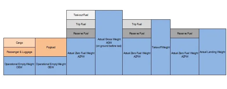
MAXIMUM DESIGN TAXI WEIGHT (MDTW OR MTW)
The maximum design taxi weight or maximum design ramp weight (MDRW) is the maximum certificated design weight for aircraft ground manoeuvres as limited by aircraft strength and airworthiness requirements. The difference between the maximum taxi/ramp weight and the maximum take-off weight (maximum taxi fuel allowance) depends on the size of the aircraft, the number of engines, APU operation, and engines/APU fuel consumption, and is typically assumed for 10 to 15 minutes allowance of taxi and run-up operations.
MAXIMUM DESIGN TAKEOFF WEIGHT (MDTOW OR MTOW)
The maximum design takeoff weight is the maximum certificated design weight for takeoff run as limited by aircraft strength and airworthiness requirements.
MAXIMUM DESIGN LANDING WEIGHT (MDLW OR MLW)
The Maximum design landing weight is the maximum certificated design weight for landing limited by aircraft strength and airworthiness requirements. It generally depends on the landing gear strength or the landing impact loads on certain parts of the wing structure.
MDLW < MDTOW < MDTW
MAXIMUM DESIGN ZERO-FUEL WEIGHT (MDZFW)
The maximum design zero-fuel weight is the maximum certificated design weight of the aircraft less all usable fuel and other specified usable agents as limited by aircraft strength and airworthiness requirements. It is the maximum weight permitted before usable fuel and other specified usable fluids are loaded in specified sections of the airplane. The weight difference between the MDTOW and the MDZFW may be utilized only for the addition of fuel.
Maximum payload = MDZFW – OEW
MINIMUM FLIGHT WEIGHT (MFW)
Minimum certificated weight for flight as limited by aircraft strength and airworthiness requirements.
EFFECTS OF WEIGHT
Some of the problems caused by overloading an aircraft are:
- The aircraft will need a higher takeoff speed, which results in a longer takeoff run.
- Both the rate and angle of climb will be reduced.
- The service ceiling will be lowered.
- The cruising speed will be reduced.
- The cruising range will be shortened.
- Maneuverability will be decreased.
- A longer landing roll will be required because the landing speed will be higher.
- Excessive loads will be imposed on the structure, especially the landing gear.
DEFINITIONS
AIRCRAFT GROSS WEIGHT
The aircraft gross weight is the total aircraft weight at any moment during the flight or ground operation.
The aircraft gross weight decreases during flight due to fuel and oil consumption. The aircraft gross weight may also vary during flight due to payload dropping or in-flight refueling.
MANUFACTURER’S EMPTY WEIGHT (MEW)
Let’s start with the aircraft itself. An aircraft “as is” includes:
- Airframe structure with all moving mechanical parts (fuselage, wings, flaps, gear, rudder, nacelle …)
- Power generation system (APU, main engines, power plant…)
- Systems (electrical, hydraulics, pneumatic, fuel flow system, instrument, navigation, air conditioning, anti-ice, fixed furnishing)
- Fixed equipment and services considered an integral part of the aircraft
- Fixed ballast
- Closed system fluids
- Unused fuel only for small aircraft
All these items above form the Manufacturer’s Empty Weight (MEW).
This weight does not include:
- Fuel
- Oil, potable water
- Payload (Cargo, passenger, luggage)
- Removable equipment
- Customer specific installations or operator items
OPERATIONAL EMPTY WEIGHT (OEW)
The MEW and the operator’s items are summed up to the Operational Empty Weight (OEW). The OEW is usually fixed for a specific aircraft and only gets changed during maintenance or operational changes. OEW is the empty weight that is used in the flight simulator or the usual planning software.
The operator’s items are:
- fluids necessary for aircraft operation (engine oil and coolant, water, unusable fuel)
- the water for galleys and lavatories
- aircraft documentation
- passenger seats (and the life vests)
- galley structure
- catering emergency equipment
- aircraft crew and their luggage.
- standard items necessary for full operation
ACTUAL ZERO FUEL WEIGHT (AZFW)
If we add the payload to the empty plane weight, we get the Actual Zero Fuel Weight (AZFW).
The payload includes:
- the passenger's weight (the standard weights used defined by ICAO respectively)
- the passenger's luggage’s weight
- the cargo weight
The assumed weights vary around some kg / lbs. depending on the number of seats available on the aircraft.
- a male passenger (incl. cabin luggage) weigh around 82kg (181 lbs.)
- a female passenger around 67kg (148 lbs.)
- a child around 50kg (110lbs.)
- an infant 16kg (35 lbs.).
These are statistical values but otherwise one would need to weigh every single passenger during check in to get his exact weight. Additional payload consists of baggage and cargo (such as mail or goods).
ACTUAL GROSS WEIGHT (AGW)
In addition to the actual zero fuel weight, we add the fuel required for the flight and we get the Actual Gross Weight (AGW). At that time, you should have calculated your total fuel for this flight. The actual gross weight is the weight of aircraft ready for departure at the gate before push-back and start-up.
|
type |
1 Litre |
1 U.S. Gallon |
1 Imp. Gallon |
|
Aviation Gas |
1.58 lb. |
6.0 lb. |
7.20 lb. |
|
JP-4 |
1.76 lb. |
6.6 lb. |
8.01 lb. |
|
Kerosene |
1.85 lb. |
7.0 lb. |
8.39 lb. |
|
Oil |
1.95 lb. |
7.5 lb. |
8.5 lb. |
Note: 1kg = 2.20462262185 lb(s)
The total fuel shall include:
- Taxi-out fuel (at departure airfield)
- Trip fuel
- Holding
- Re-routing expectation
- regulation needs depending on your route arrival airfield
- fuel to join alternate airfield
- taxi-in fuel at destination,
- final reserve
TAKE-OFF WEIGHT
Fuel burn during taxi operation to the departure runway reduces the gross weight. At the holding point, we have the Actual Take-off Weight (ATOW) which is used for take-off performance calculation.
The gross weight varies during flight. Fuel and oil consumption reduces the gross weight. Additionally it may vary during flight due to inflight refuelling or payload dropping.
MAXIMUM DESIGN TAKEOFF WEIGHT (MDTOW)
The maximum takeoff weight (also known as the maximum brake-release weight) is the maximum weight authorized at brake release for takeoff, or at the start of the takeoff roll.
The maximum takeoff weight is always less than the maximum taxi/ramp weight to allow for fuel burned during taxi by the engines and the APU.
In operation, the maximum weight for takeoff may be limited to values less than the maximum takeoff weight due to aircraft performance, environmental conditions, airfield characteristics (takeoff field length, altitude), maximum tire speed and brake
At this weight, the subsequent addition of fuel will not result in the aircraft design strength being exceeded. The weight difference between the MTOW and the MZFW may be utilized only for the addition of fuel.
LANDING WEIGHT
With the calculation of fuel consumption during flight, we can calculate the Estimated Landing Weight (ELW) which is used for landing performance calculation at the destination.
Approaching your destination you use your current gross weight to determine the final approach speed. The gross weight now is the Actual Landing Weight (ALW).
Of course before landing, you never land without any fuel in reserve. The regulation is strict about fuel calculation for commercial air transportation including reserve fuel. Except in specific situations like re-routing, multiple holding, landing at alternate or technical problems, at landing, the aircraft shall still have the expected reserve fuel if there was no extra consumption.
GRAPHICAL SUMMARY OF OPERATIONAL WEIGHT
Example:-
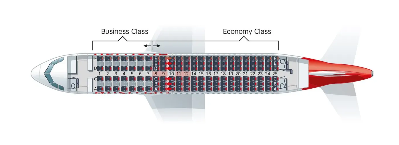
Now we will get started and calculate an example (we operate an Airbus A319):
| Manufacturer’s Empty Weight (MEW) | 36,779 kg |
| + Operator’s Items | + 5,205 kg |
| = Operational Empty Weight (OEW) | = 41,981 kg |
| + Payload | + 13,529 kg |
| = Actual Zero Fuel Weight (AZFW) | = 55,510 kg |
| + Fuel | + 13,239 kg |
| = Actual Gross Weight (AGW) | = 68,749 kg |
| - Taxi Fuel | - 100 kg |
| = Actual Take-Off Weight (ATOW) | = 68,649 kg |
| Fuel consumption | -10,900 kg |
| = Actual Landing Weight (ALW) | = 57,749 kg |
2)difference between ground speed and air speed:-
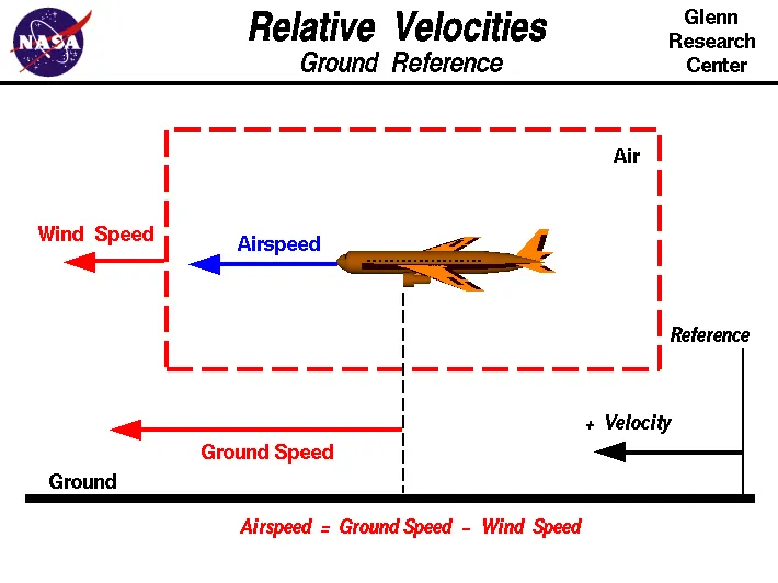
Wind Speed :-
For a reference point picked on the ground, the air moves relative to the reference point at the wind speed. Notice that the wind speed is a vector quantity and has both a magnitude and a direction. Direction is important. A 20-mph wind from the west is different from a 20-mph wind from the east. The wind has components in all three primary directions (north-south, east-west, and up-down). In this figure, we are considering only velocities along the aircraft's flight path. A positive velocity is defined to be in the direction of the aircraft's motion. We are neglecting cross winds, which occur perpendicular to the flight path but parallel to the ground, and updrafts and downdrafts, which occur perpendicular to the ground.
Ground Speed :-
For a reference point picked on the ground, the aircraft moves relative to the reference point at the ground speed. Ground speed is also a vector quantity so a comparison of the ground speed to the wind speed must be done according to rules for vector comparisons.
Airspeed :-
The important quantity in the generation of lift is the relative velocity between the object and the air, which is called the airspeed. Airspeed cannot be directly measured from a ground position, but must be computed from the ground speed and the wind speed. Airspeed is the vector difference between the ground speed and the wind speed.
Airspeed = Ground Speed - Wind Speed
conclusion:-
Yes, there is a difference between ground speed and air speed. Ground speed is how fast an airplane's shadow would move across the land. If there's a strong wind pushing an aircraft, that's reflected in the ground speed. Airspeed, in contrast, is how fast an airplane is really flying strictly under its own power, which is calculated by subtracting the wind speed from the ground speed. On a perfectly still day, the airspeed is equal to the ground speed. But if the wind is blowing in the same direction that the aircraft is moving, the airspeed will be less than the ground speed.
3. Why is it not recommended to use aircraft engine power to move it on the ground at Airport:-
The Risk to Operational Safety:-
The risks which may arise from engine ground running relate to the potential for loss of control of the aircraft by those persons occupying the pilot seats in the flight deck. In most cases, such persons will be maintenance personnel holding specific company-issued approval for the required tasks. The consequences of loss of control during taxi or towing are the same as apply to these operations generally and this article is concerned only with the risks arising from the static running of one or more aircraft engines. Unwanted consequences from such static running are mainly related to those arising from the unintended movement of the aircraft during engine running - effectively a loss of control - especially during high power engine running. Damage can occur to the aircraft itself, other aircraft nearby or to airside structures. In addition, there is a risk of injury to ground support personnel who may be in relatively close proximity to the aircraft.
reasons for not using aircraft engine power to move it on the ground at Airport:-
1) Usage of high power mounted engines have high risk of blasting.
2) Usage of low power mounted engines have a risk of impurities on the ground may enter inside the engine.
3) High fuel cost since areoplanes uses large amount of power.
4.How an aircraft is pushed to runway when its ready to take off:-
Taxiing is the movement of an aircraft on the ground, under its own power, in contrast to towing or pushback where the aircraft is moved by a tug. The aircraft usually moves on wheels, but the term also includes aircraft with skis or floats (for water-based travel).
A pushback truck lifts the front weel of the aircraft, their role in most airports is to move the aircraft away from the parking spot on to the taxiways. Here the truck is removed and when all platform staff is out of the way the engines are started one by one. From here on the aircraft moves on its own power to the runway. In the aircraft you will hear the engine spinning up when power is demanded for acceleration.
An airplane uses taxiways to taxi from one place on an airport to another; for example, when moving from a hangar to the runway. The term "taxiing" is not used for the accelerating run along a runway prior to takeoff, or the decelerating run immediately after landing, which are called the takeoff roll and landing rollout, respectively.
5. Learning about take off power, tyre design, rolling resistance, tyre pressure, brake forces when landing:-
a)take off power:-
Takeoff is the phase of flight in which an aerospace vehicle leaves the ground and becomes airborne. For aircraft traveling vertically, this is known as liftoff. For aircraft that take off horizontally, this usually involves starting with a transition from moving along the ground on a runway. For light aircraft, usually full power is used during takeoff. Large transport category (airliner) aircraft may use a reduced power for takeoff, where less than full power is applied in order to prolong engine life, reduce maintenance costs and reduce noise emissions.
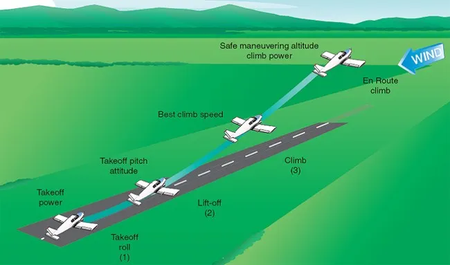
After taxiing onto the runway, the airplane should be carefully aligned with the intended takeoff direction, and the nose wheel positioned straight, or centered. After releasing the brakes, the throttle should be advanced smoothly and continuously to takeoff power. An abrupt application of power may cause the airplane to yaw sharply to the left because of the torque effects of the engine and propeller. This will be most apparent in high horsepower engines. As the airplane starts to roll forward, the pilot should assure both feet are on the rudder pedals so that the toes or balls of the feet are on the rudder portions, not on the brake portions.
Takeoff performance can be predicted by using a simple measure of Acceleration of the aircraft anong the runway based on force equilibrium.
The force involved will be
T- Thrust of propulsion system pushing aircraft along runway
D- Areodynamic Drag of vehicle resisting the aircraft motion.
F- Rolling resistance friction due to the contact of wheels of skids on the ground.
During take –off run the imbalance in these forces will produce an acceleration along the runway
DV/dt = (T-D-F)/m
Where dV/dt is the acceleration along the runway and m is the mass of the vehicle.
b)tyre design:-
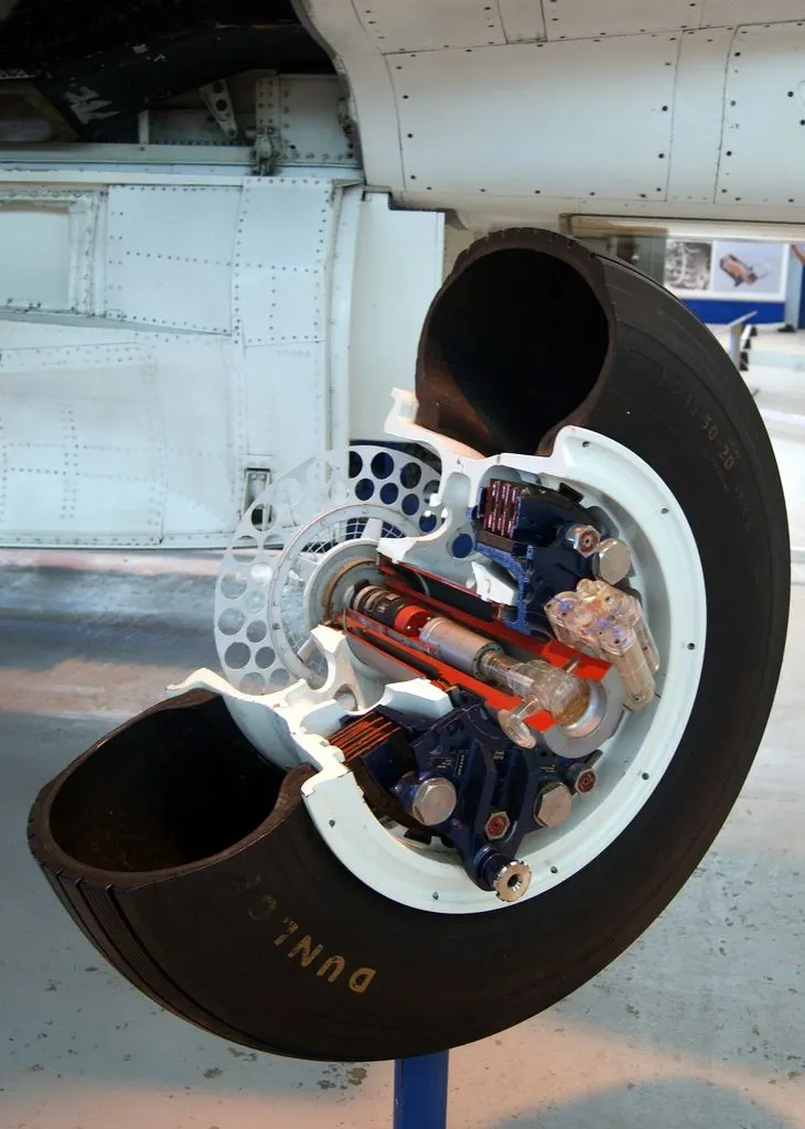
When it comes to safety, Tyres are one of the most important components of aircraft. They help to absorb the shock of landing and provide cushioning. It also provides the necessary traction for braking and stopping of an aircraft. An aircraft Tyre is designed to withstand extremely heavy loads while landing, take off, taxing, and parking. The number of wheels required for aircraft increases with the weight of the aircraft, as the weight of the aero plane needs to be distributed more evenly.
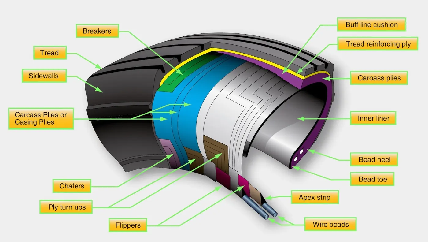
Carcass plies are used to form the tire. They are sometimes called casing plies. An aircraft Tyre is constructed for the purpose it serves.
- They support the weight of an aircraft while it is on the ground.
- It also provides the necessary traction for braking and stopping of an aero plane.
- Tyre also helps to absorb the shock of landing and provide cushioning the roughness of takeoff, roll-out, and taxi operations.
Unlike an automobile or truck Tyre, it does not have to carry a load for a long period of continuous operation. However, an aircraft Tyre absorbs the high impact loads of landing, and also, it’s operating at high speeds for a short time when required.
c)Rolling Resistance:-
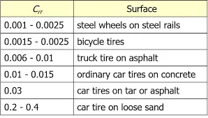
Rolling resistance, sometimes called rolling friction or rolling drag, is the force resisting the motion when a body (such as a ball, tire, or wheel) rolls on a surface. It is mainly caused by non-elastic effects; that is, not all the energy needed for deformation (or movement) of the wheel, roadbed, etc., is recovered when the pressure is removed. Two forms of this are hysteresis losses (see below), and permanent (plastic) deformation of the object or the surface (e.g., soil). Note that the slippage between the wheel and the surface also results in energy dissipation. Although some researchers have included this term in rolling resistance, some suggest that this dissipation term should be treated separately from rolling resistance because it is due to the applied torque to the wheel and the resultant slip between the wheel and ground, which is called slip loss or slip resistance. In addition, only the so-called slip resistance involves friction, therefore the name "rolling friction" is to an extent a misnomer.
The "rolling resistance coefficient" is defined by the following equation:

where
 = Rolling resistance force
 = dimensionless rolling resistance coefficient or coefficient of rolling friction (CRF)
- N = Normal force, the force perpendicular to the surface on which the wheel is rolling.
Tyre pressure:-
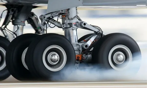
The typical airliner tire can handle a 38-ton load. It can meet the ground 500 times before needing a re-tread, a refresh it can take on seven times in its life. Aircraft tires generally operate at high pressures, up to 200 psi (14 bar; 1,400 kPa) for airliners, and even higher for business jets. The main landing gear on the Concorde was typically inflated to 232 psi (16.0 bar), whilst its tail bumper gear tires were as high as 294 psi (20.3 bar).
d)Brake forces:-
In aircraft types, the brake units are powered by the hydraulics system. An electrical signal is sent from the flight deck to hydraulic actuators near the main landing gear. Here, hydraulic fluid at 3,000 pound per square inch is used to force the brake unit against the wheel, thus slowing it down.
Part B:-
6. A. calculating the force and power required to push / pull an aircraft by a towing vehicle:-
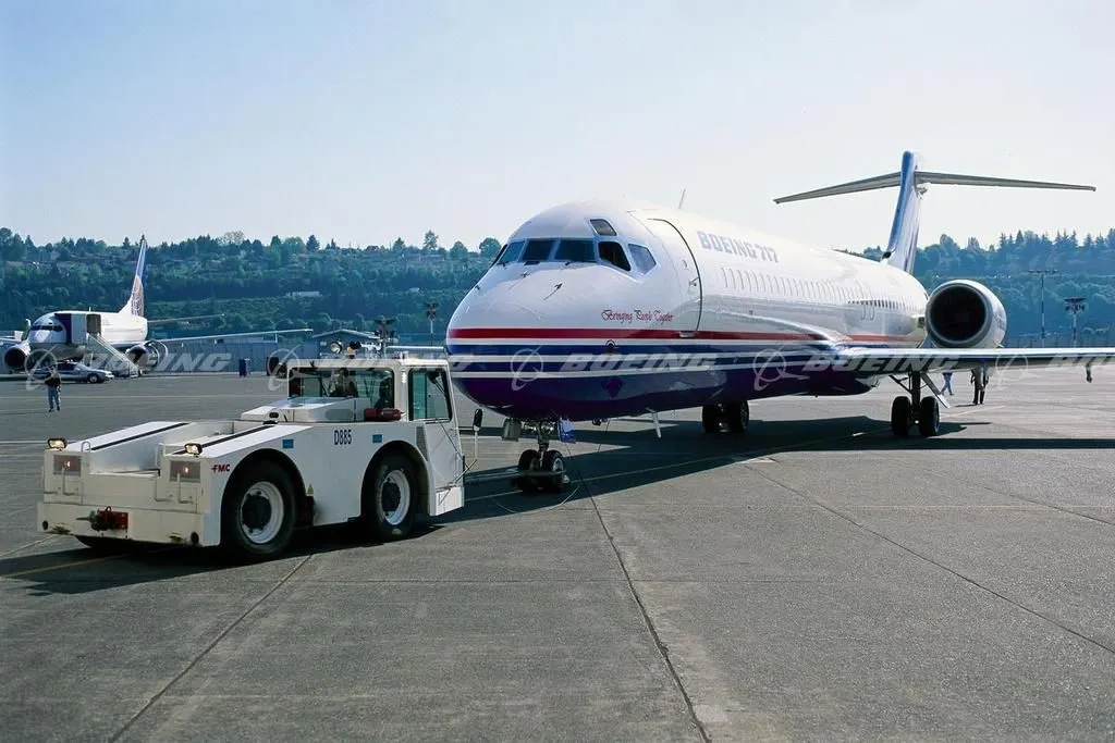
The forces required to push/ pull an aircraft by a towing are rolling resistance force and areodynamic drag force.
1)Rolling resistance force:- As we have discussed in part-A 5c. It is the force resisting the motion when a body (such as a ball, tire, or wheel) rolls on a surface. Its governing equation is given as
F= *m*g
where,
= Rolling resistance coefficient
m= Mass of the body
g= acceleration due to gravity
2)Aerodynamic Drag Force:-
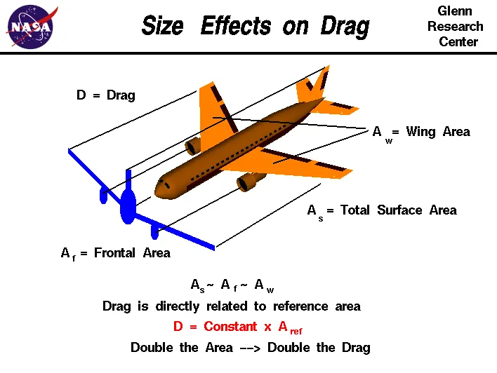
It is the force opposing the motion of the body. The drag coefficient is a common measure in automotive design as it pertains to aerodynamics. Drag is a force that acts parallel to and in the same direction as the airflow. The drag coefficient of an automobile measures the way the automobile passes through the surrounding air. When automobile companies design a new vehicle, they take into consideration the automobile drag coefficient in addition to the other performance characteristics. Aerodynamic drag increases with the square of speed; therefore, it becomes critically important at higher speeds. Reducing the drag coefficient in an automobile improves the performance of the vehicle as it pertains to speed and fuel efficiency. The governing equation of these force is given as following:

where,
 = drag force
 = mass density of the air
 = flow velocity relative to the object
 = drag coefficient
 = reference area
Calculation:-
let us assume that,
Mass of Towing Vehicle= 40,000kg
Mass of aircraft = 155,000kg
Total mass (m)= 40,000+155,000 =195,000kg
Frontal Area of the aircraft (A) =18 m2
Speed of the vehicle ( ) =25Kmph
converting it into m/sec
= 25*(1000/3600)=6.9445m/sec
Drag coefficient (Cd) =0.75
Air density ( ) =1.225Kg/m3
Calculating Rolling resistance Force (Frr) = *m*g
= 0.01*195,000*9.8
= 19,110N
Calculating Aerodynamic Drag Force (Fd)=0.5* * Cd*A* v^2
=0.5*1.225*18*0.75*(6.9445)2
=398.769N
Therefore the total Force required to push/pull the aircrcraft by the towing vehicle (F) = Frr+ Fd
= 19,110+ 398.769
= 19,508.769 N
Calculating the power (p) = Force*Velocity
= 19508.769* 6.9445
=135.478kW
B. Developing the model for the calculated force and power using Simulink:-
Blocks Used:-
1)Constant
2)Sum
3)Product
4)Square
5)Display
Link:- https://drive.google.com/file/d/1y9HWI5uCSQNqT9okv930sX0XnCyRQj1n/view?usp=sharing
Simulink Model:-
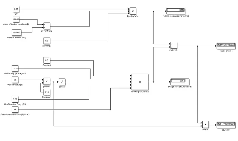
Explaination:-
In order to understand the above simulink model we do reverse engineering.
- For calculating power we have to multiply both total force(F) and velocity in m/sec for this we have used 'product' block (P=F*V).
- For calculating the Total Force(F) we have added both Frr & Fd by using 'Sum' block as shown in the above figure.
- To find the value of rolling resistance (Frr) we used product to multiply the values Crr, Total mass(m) & gravity (g) which are to be entered in the 'Constant' block.
- Similarly for calculating Drag force(Fd) we have to multiply the velocity in m/sec,Drag coefficient, Frontal area of aircraft(A) and a constant value 0.5 which are to be entered in 'constant' block.
- In order to convert velocity in Kmph to m/sec we have multiplied it with 5/18.
7) A. Designing an electric powertrain with type of motor, it’s power rating, and energy requirement to fulfill aircraft towing application in Simulink. Estimate the duty cycle range to control the aircraft speed from zero to highest. Make all required assumptions. Prepare a table of assumed parameters. Draw a block diagram of powertrain.
Block Diagram of Powertrain:-
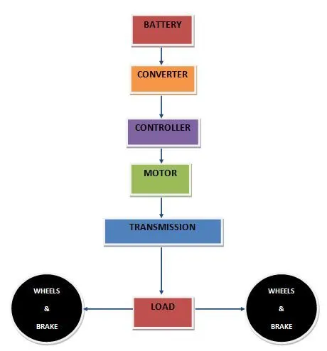
Based on the calculations done in 6A.
Force required to push/pull the aircraft =19.508 KN
Power required =135.478 kw
Let us assume,
The Radius of the Tyre for the Tug = 25inches =0.635m
Gear ratio = 8
Transmission Effeciency (ηt) =87%
Motor Efficiency (ηm)=95%
then,
Torque required for the wheels (Tw)=Total Force *Radius in meters
=19.508*0.635
= 12.387KNm
Motor Torque= Wheel torque/(Gear ratio*ηt)
= 12.387 / (8*0.87)
= 1.778KNm
For ηm =95%, The required motor Torque (Tm)= 1.778/0.95 =1.871 kNm
Similarly, The total power required by the motor considering all the efficiencies(Pt) = 135.478/(0.87*0.95)=163.917Kw
Let us assume the towing operation was done for a 15 minutes (0.25Hrs) duration.
Then, Total Energy consumed = 163.917*0.25 = 40.98 KWh
If we consider the battery capacity =220 kw is used by the towing vehicle then, The duty cycle range to control the speed from 0 to max speed (3m/s) is given as
Duty Cycle (d) = (Required Power)/ (Rated power)= 163.917/220 =0.75
Therefore the controller will be able to provide a duty cycle ranging from 0 to 75% in order to control the towing speed.
Simulink Diagram of powertrain:-
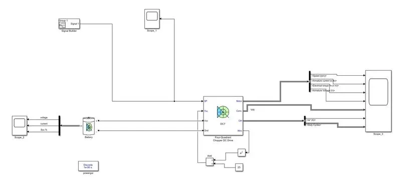
Google Drive Link: https://drive.google.com/file/d/11BDawsbEckg-qjNj5_nyH036rk4Whd01/view?usp=sharing
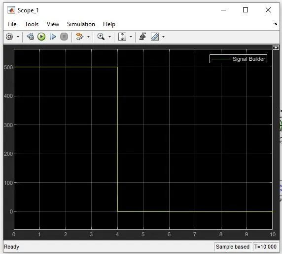
Inputs:-
Scope_1: Signal builder
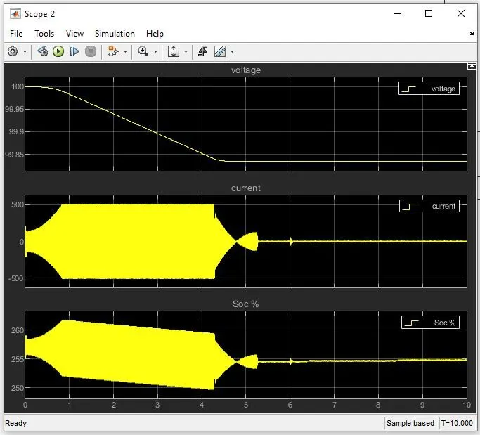
Scope_2 : Battery
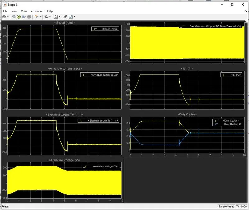
Output:-
Scope_3: DC Drive output
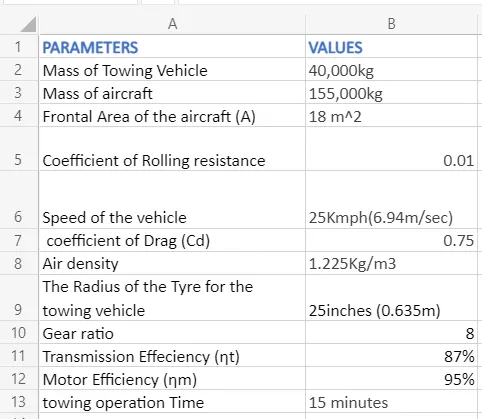
B. Designing the parameters in excel sheet.
Reference: -
1) Wikipedia
2)https://mediawiki.ivao.aero/index.php?title=Standard_aircraft_weight