Final Project: Design of an Electric Vehicle
Aim:- Create a MATLAB model of electric car which uses a battery and a DC motor. Choose suitable blocks from Powertrain block set. Prepare a report about your model including following:
Objectives:-
1. System level configurations
2. Model parameters
3. Results
4. Conclusion
Introduction to Electric Vehicles:-
An electric vehicle (EV) is a vehicle that uses one or more electric motors or traction motors for propulsion. An electric vehicle may be powered through a collector system by electricity from off-vehicle sources, or may be self-contained with a battery, solar panels, fuel cells or an electric generator to convert fuel to electricity. EVs include, but are not limited to, road and rail vehicles, surface and underwater vessels, electric aircraft and electric spacecraft.
EVs first came into existence in the mid-19th century, when electricity was among the preferred methods for motor vehicle propulsion, providing a level of comfort and ease of operation that could not be achieved by the gasoline cars of the time. Modern internal combustion engines have been the dominant propulsion method for motor vehicles for almost 100 years, but electric power has remained commonplace in other vehicle types, such as trains and smaller vehicles of all types.
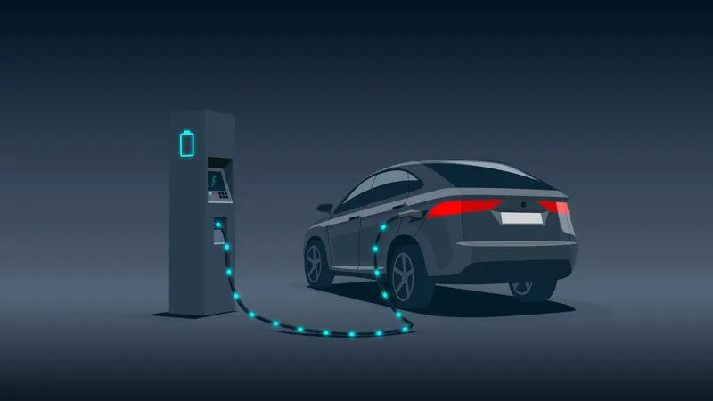
Commonly, the term EV is used to refer to an electric car. In the 21st century, EVs have seen a resurgence due to technological developments, and an increased focus on renewable energy and the potential reduction of transportation's impact on climate change and other environmental issues. Project Drawdown describes electric vehicles as one of the 100 best contemporary solutions for addressing climate change.
Government incentives to increase adoption were first introduced in the late 2000s, including in the United States and the European Union, leading to a growing market for the vehicles in the 2010s. Increasing public interest and awareness and structural incentives, such as those being built into the green recovery from the COVID-19 pandemic, is expected to greatly increase the electric vehicle market. A pre-COVID 2019 analysis projected that Electric vehicles are expected to increase from 2% of global share in 2016 to 22% in 2030. Much of this market growth is expected in markets like North America and Europe.
System Level Configuration: -
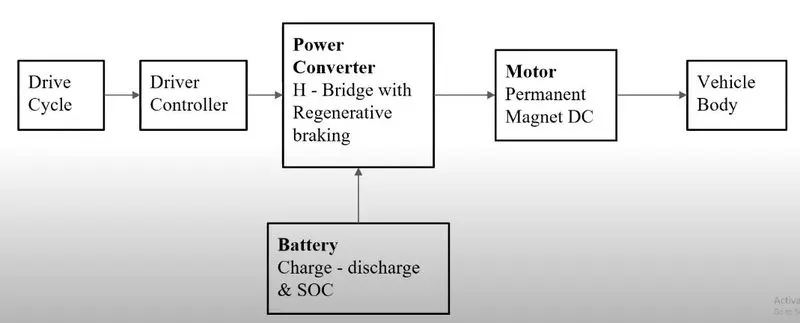
To create a Simulink model of electric car in MATLAB, we need to create different subsystems separately which consist of many individual components and then assembled together to create a full working design.
Block Diagram of Subsystems in Electric car:-
Subsystems:-
1) creating Vehicle Body:-
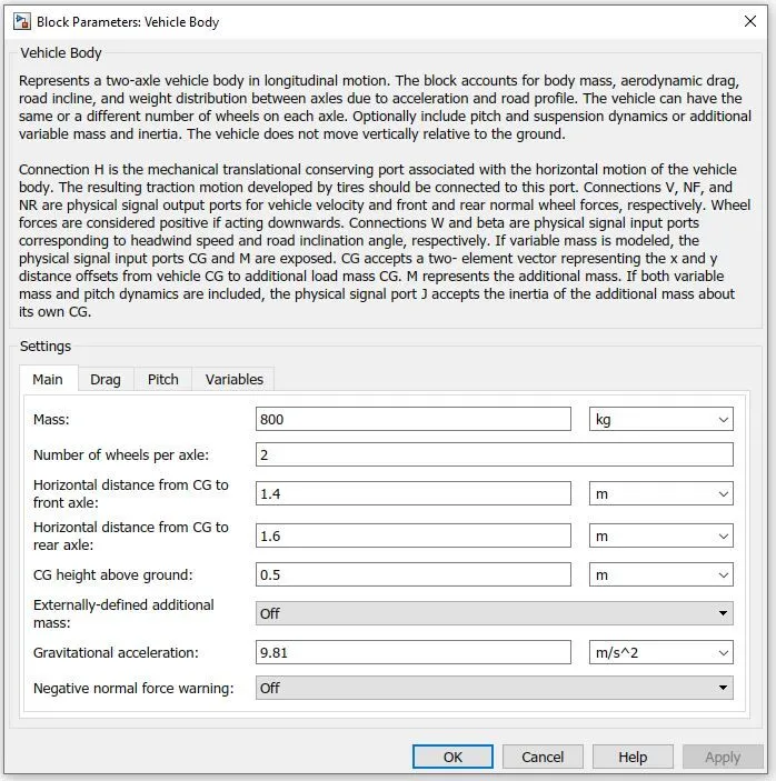
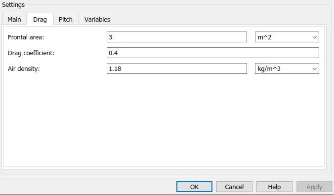
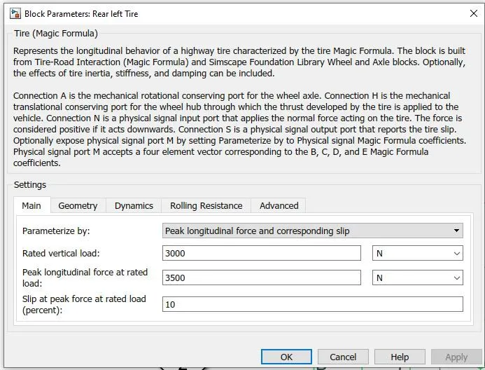
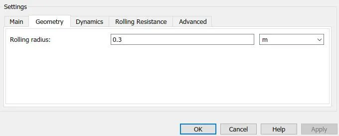
Requred Blocks and their parameters are shown below:-
a)Vehicle Body:-
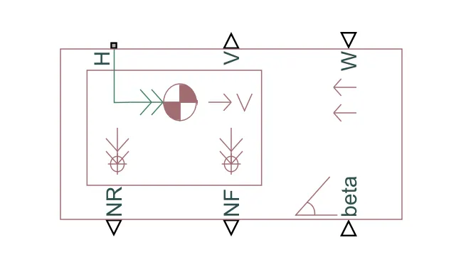
Ports:-
- H- It stands for 'Hub' and it connects the wheels Hub to the main vehicle body.
- V- It stands for 'Velocity' measured in m/sec and its a physical signal output port.
- W-It stands for 'headwind speed' and its a physical signal input port of vehicle body.
- NR-It stands for 'Rear Normal Force' and its a physical signal output port which is to be connected to wheel.
- NF-It stands for 'Front Normal Force' and its a physical signal output port which is to be connected to wheel.
- beta-It stands for 'inclination angle' and its a input physical signal which allows the model of vehicle on an inclination angle to create a hillclimbing force effect.
Note:- For block parameters modification left double click on required block with the help of mouse.
b. Tire:-
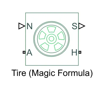
The tire block consists of four ports and they are
- N- It stands for 'Normal' and it is a phsical signal input port from here we provide the normal force acting on the tire.
- A- It is the mechanical rotational conserving port for the wheel axle
- S- It stands for 'Slip', This port reports the slip acting on the tire.
- H- It is the mechanical translational conserving port for the wheel hub.
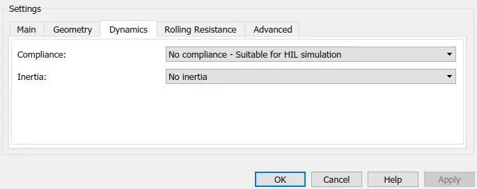
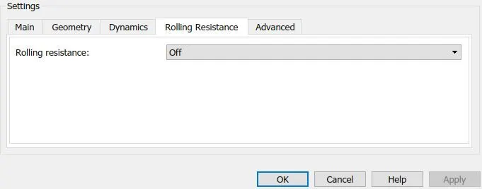
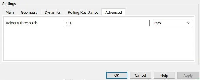
c. Simple Gear:-
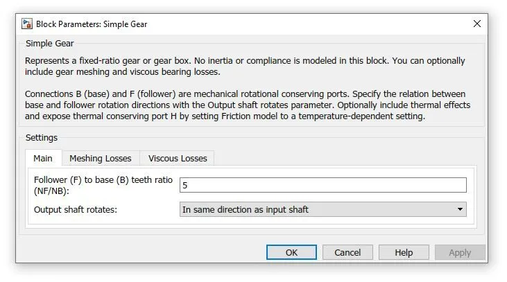
This block represents a gear system with fixed gear ratio with no inertia effects, However we can modify the effects of meshing of the gear teeth. The 'simple gear' block is shown below.
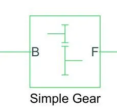
In the below Block parameters the teeth ratio was kept at 5 and the remaining values ofparameters like meshing losses and viscous losses are not changed.
d.Simulink- PS converter:-
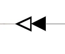
This block Converts the Simulink input signal to a Physical Signal .The red colour line shows physical signal and black colour line represents a simulink input signal.The 'Simulink- PS converter' block is shown below.
e.Constant:-
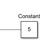
Output the constant specified by the 'Constant value' parameter. If 'Constant value' is a vector and 'Interpret vector parameters as 1-D' is on, treat the constant value as a 1-D array. Otherwise, output a matrix with the same dimensions as the constant value.
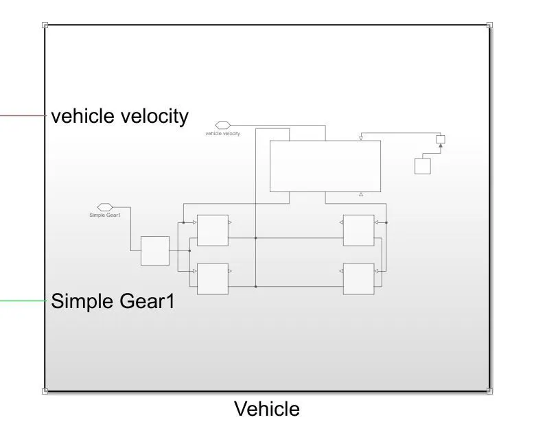
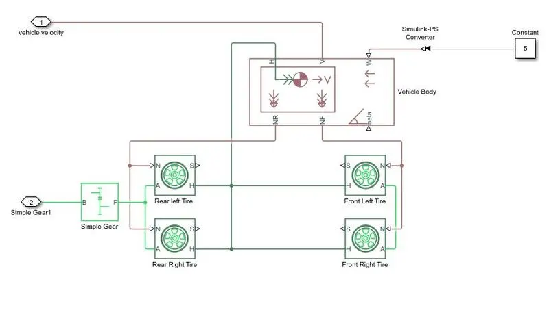
Vehicle Subsystem:- With the help of mentioned above blocks and the same parameters the simulink 'vehicle' subsystem is created and it is shown below.
Discription:-
- There are four Tires in the above figure, In this two tires represents the front and other two represents the rear tires of an electric car.
- The front and rear tires axles (A-Port) are connected to their respective left and right as shown in the above figure.
- A simple gear is connected to the axle of the rear tires.
- The hub (H-port) of all the four tires are connected together and finally connected to the hub (H-port) of vehicle body.
- We are neglecting the slip of tires hence S-ports are kept untouched.
- The two normal (N-ports) of rear tires are connected to the Normal Rear (NR-port) of the vehicle body. Similarly two normal (N-ports) of front tires are connected to the Normal Front (NF-port) of the vehicle body.
- Beta port of the vehicle body is untouched . we are considering there is no inclination angle since The vehicle is not travelling on hills or flyovers.
- A constant of 5 is is provided to W-port with the help of simulink to PS converter of vehicle body, which represent the wind velocity is 5m/sec.
2)Creating DC Motor Subsystem:-
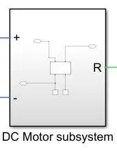
This block basically consist of three sub blocks and they are
a)DC Motor
b)Mechanical rotational reference
c)Electrical reference
The sub system connections are shown below in which electrical circuits are represented in blue colour and electrical reference is connected to negitive terminal of motor. Here the mechanical circuits are represented in green colour and Mechanical rotational reference is connected to the C-port of the DC motor.
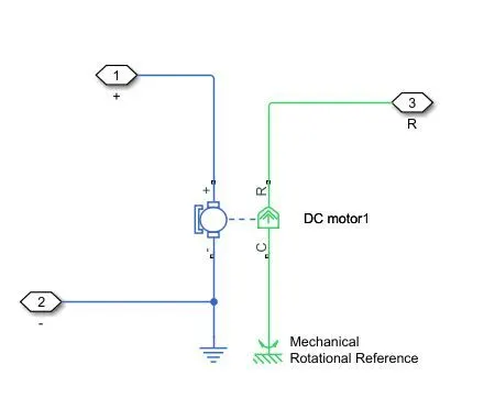
a)DC Motor:-
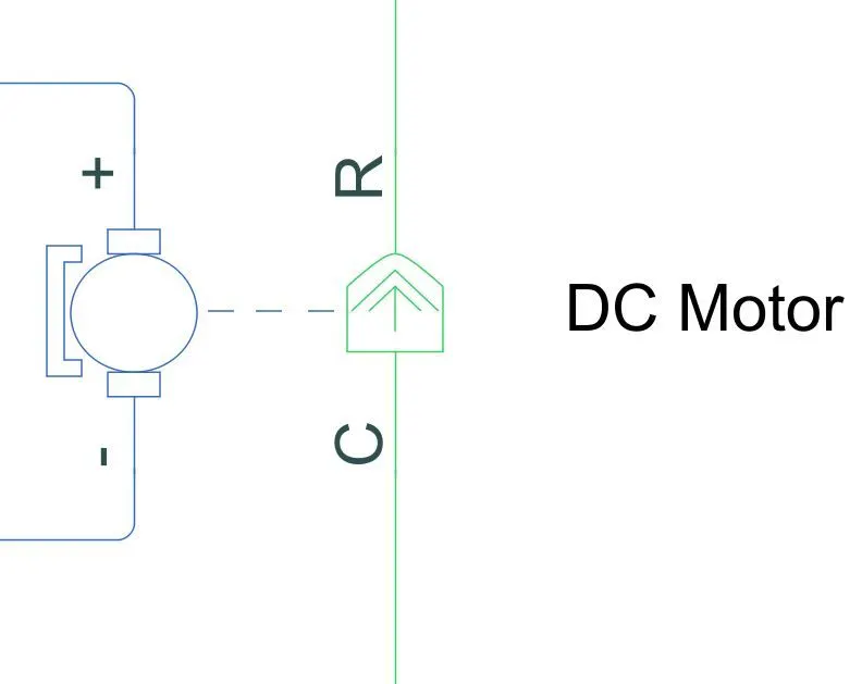
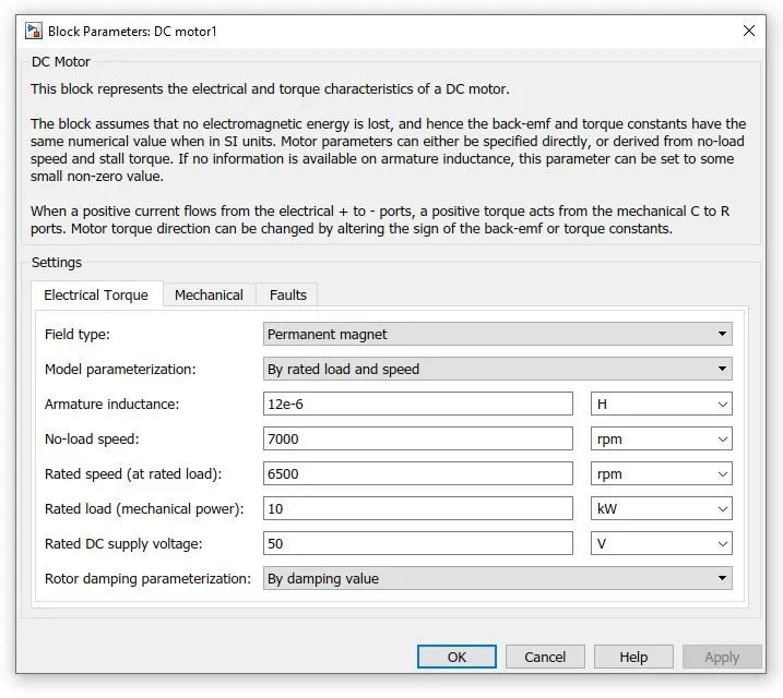
The above figure is simulinlk block of permanent magnet brushed DC motor and the block parameters are shown below.In settings the mechanical and fault options are kept untouched.
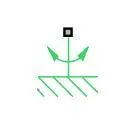
b)Mechanical rotational reference
This block represents a mechanical rotational reference point, that is, a frame or a ground. Use it to connect mechanical rotational ports that are rigidly affixed to the frame (ground).
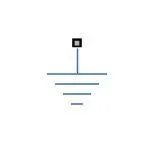
c)Electrical reference
Electrical reference port. A model must contain at least one electrical reference port (electrical ground).
3)Creating Power Converter (H-Bridge with Regenerative braking):-
An H-bridge is an electronic circuit that switches the polarity of a voltage applied to a load. These circuits are often used in robotics and other applications to allow DC motors to run forwards or backwards. In case of EV's, power converter takes the DC supply voltage from the battery at one level and provides the DC voltage to the DC motor at another level. The H-bridge block is shown below.
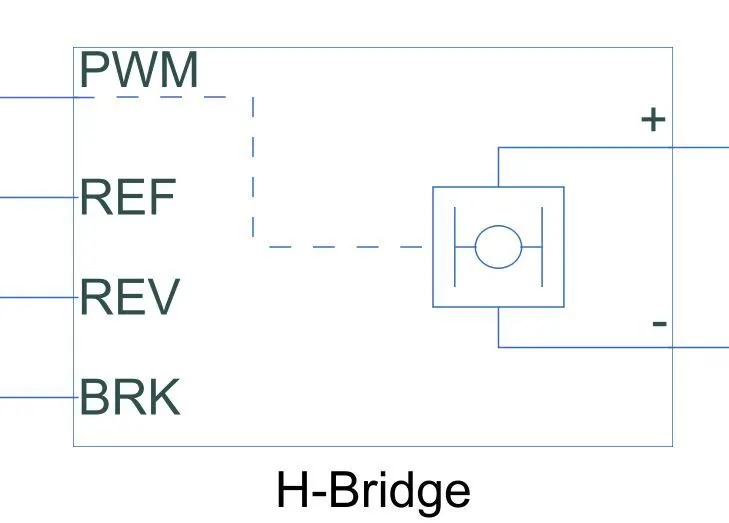
The H-bridge block has 6 ports in which positive (+) and negitive (-) ports are connected to the DC motor.
PWM- It stands for Pulse Width Modulation
REF- Stands for Reference.
REV- Stands for Reverse.
BRK- Stands for Brake.
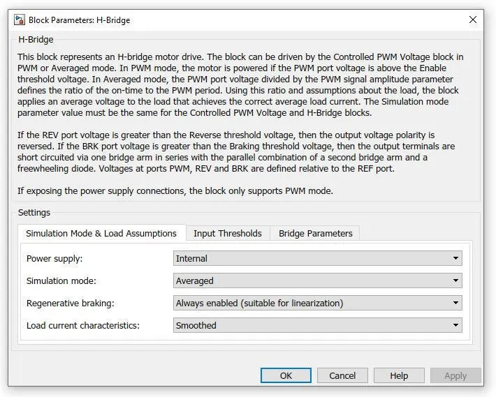
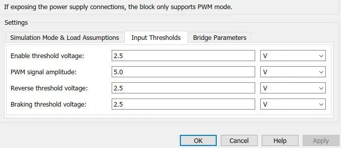
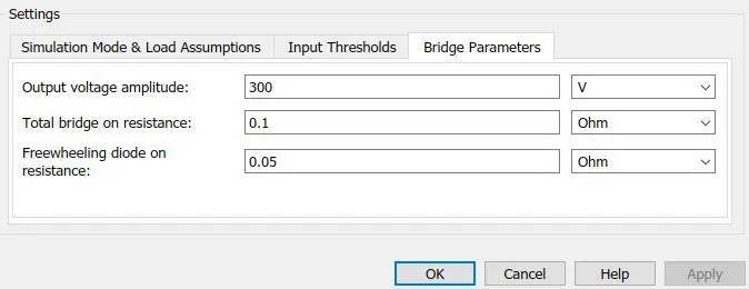
By opening the H-bridge block parameters the below figure is displayed and the following settings are selected.
4)Creating Driver controller
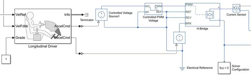
The driver controller takes the input drive cycle and provides PWM voltage signal to the H-brige circuit.
Simulink Blocks used are
a)longitudinal Driver
b)Controlled Voltage Source
c)Controlled PWM Voltage
d)Terminator
a)longitudinal Driver :-
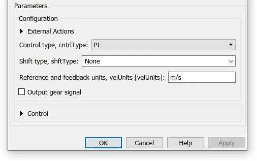
A parametric longitudinal speed tracking controller for generating normalized acceleration and braking commands based on reference and feedback velocities. Use the external actions to input signals that can disable, hold, or override the closed-loop commands determined by the block. The block uses this priority for the input commands: disable, hold, override.
The block parameter is shown below.
b)Controlled Voltage Source :-
The block represents an ideal voltage source that is powerful enough to maintain the specified voltage at its output regardless of the current passing through it. The output voltage is V = Vs, where Vs is the numerical value presented at the physical signal port.
c)Controlled PWM Voltage:-
This block creates a Pulse-Width Modulated (PWM) voltage across the PWM and REF ports. The output voltage is zero when the pulse is low, and is equal to the Output voltage amplitude parameter when high. Duty cycle is set by the input value. Right-click the block and select Simscape->Block choices to switch between electrical +ref/-ref ports and PS input u to specify the input value.
Its block settings are shown below.
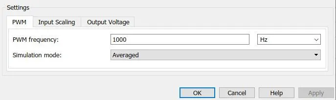
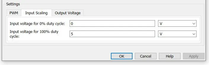
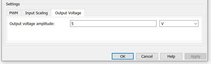
At time zero, the pulse is initialized as high unless the duty cycle is set to zero or the Pulse delay time is greater than zero.The Simulation mode can be set to PWM or Averaged. In PWM mode, the output is a PWM signal. In Averaged mode, the output is constant with value equal to the averaged PWM signal.
d)Terminator
It Prevents warnings about unconnected output ports.
5)Creating Drive Cycle Sub system:-
A driving cycle is a series of data points representing the speed of a vehicle versus time.
Driving cycles are produced by different countries and organizations to assess the performance of vehicles in various ways, as for instance fuel consumption, electric vehicle autonomy and polluting emissions. Fuel consumption and emission tests are performed on chassis dynamometers. Tailpipe emissions are collected and measured to indicate the performance of the vehicle.
Another use for driving cycles is in vehicle simulations. More specifically, they are used in propulsion system simulations to predict performance of internal combustion engines, transmissions, electric drive systems, batteries, fuel cell systems, and similar components. Some driving cycles are derived theoretically, as it is preferred in the European Union, whereas others are direct measurements of a driving pattern deemed representative.
The Drive Cycle subsystem consist of four simulink blocks is shown below.
a)Drive cycle source
b)Signal Builder
c)Multiport Switch
d)Constant
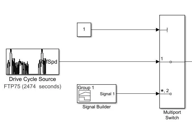
a)Drive cycle source
In this block we are selecting the FTP75 Drive cycle source and the graph of input drive cycle is shown below.
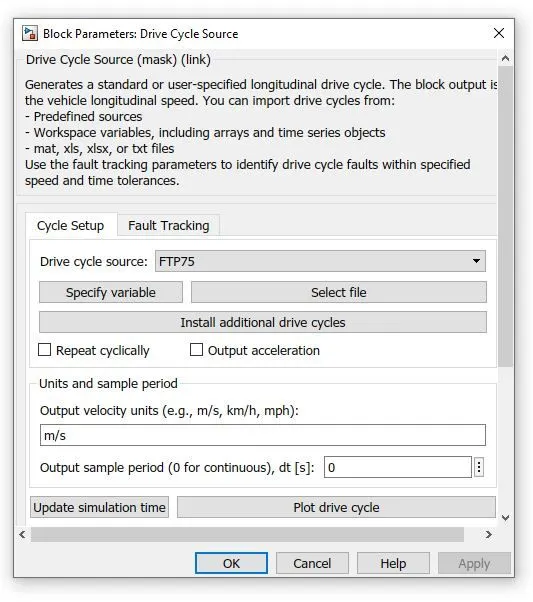
Input Graph:-
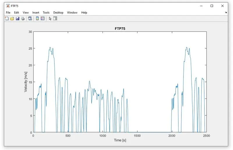
b)Signal Builder
In signal builder we can built our own signal and give as drive cycle input to the Electric Vehicles(EV) in Simulink.
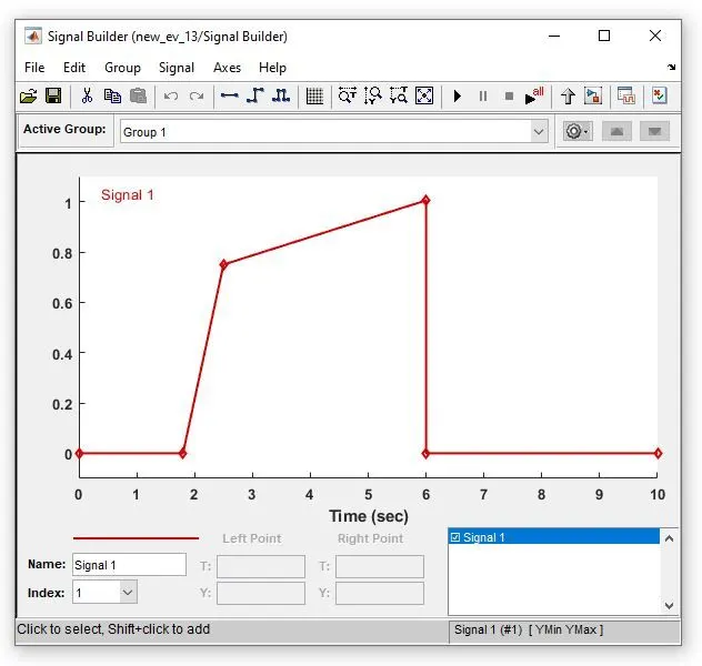
c)Multiport Switch
It helps to Pass through the input signals corresponding to the truncated value of the first input. The inputs are numbered top to bottom (or left to right). The first input port is the control port. The other input ports are data ports.Here we used multiport switch for switching between signal builder and drive cycle source input.
d)Constant
Here we have used the constant to shift between the two drive cycles.
6) Battery System and SOC(State of Charge):-
a) Battery System:
The battery system consist of a battery whose negitive is connected to electrical reference. A controlled current source connection to the battery is shown below.The battery will dischage according to the current taken out by the DC Motor witht the help of a current sensor connected to controlled current source.
Blocks used are
1)Battery
2)Contolled Current Source
3)Current Sensor
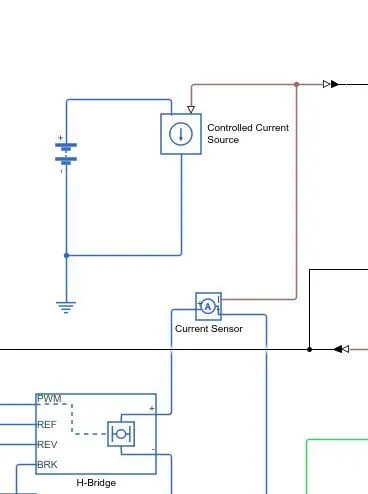
1)Battery:-
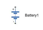
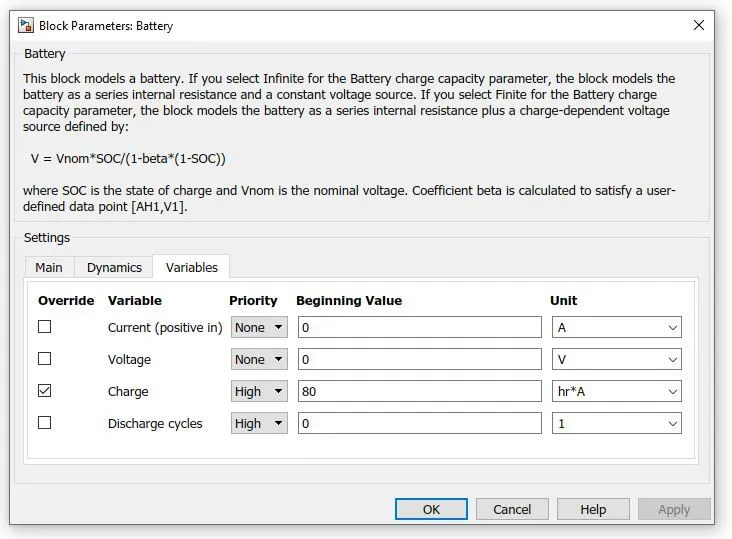
This block models a battery. If you select Infinite for the Battery charge capacity parameter, the block models the battery as a series internal resistance and a constant voltage source. If you select Finite for the Battery charge capacity parameter, the block models the battery as a series internal resistance plus a charge-dependent voltage source defined by:
V = Vnom*SOC/(1-beta*(1-SOC))
where SOC is the state of charge and Vnom is the nominal voltage. Coefficient beta is calculated to satisfy a user-defined data point [AH1,V1].
The block parameters are shown below
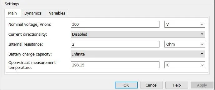
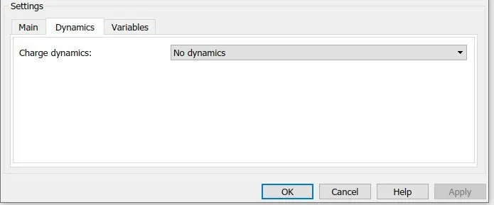
2)Contolled Current Source
The block represents an ideal current source that is powerful enough to maintain the specified current through it regardless of the voltage across it. The output current is I = Is, where Is is the numerical value presented at the physical signal port.
3)Current Sensor
The block represents an ideal current sensor, that is, a device that converts current measured in any electrical branch into a physical signal proportional to the current.Connections + and - are conserving electrical ports through which the sensor is inserted into the circuit. Connection I is a physical signal port that outputs current value.
b)SOC (State of Charge):-
State of charge (SoC) is the level of charge of an electric battery relative to its capacity. The units of SoC are percentage points (0% = empty; 100% = full). An alternative form of the same measure is the depth of discharge (DoD), the inverse of SoC (100% = empty; 0% = full). SoC is normally used when discussing the current state of a battery in use, while DoD is most often seen when discussing the lifetime of the battery after repeated use. The SOC subsystem is shown below.
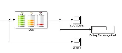
The Block inside the SOC subsystem are shown below.
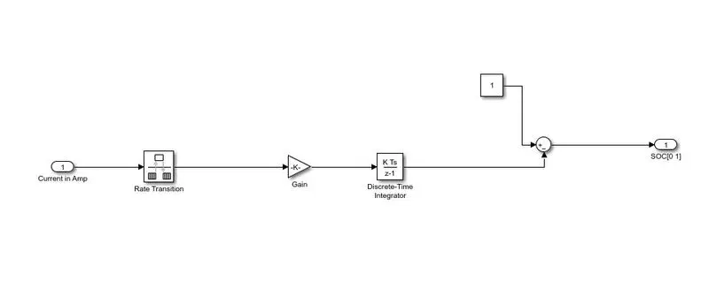
The block and their parameters are shown below
1)Rate Transition
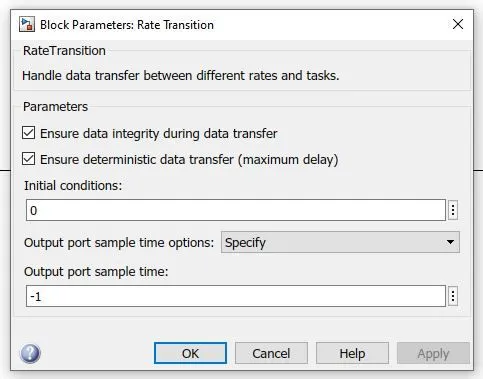
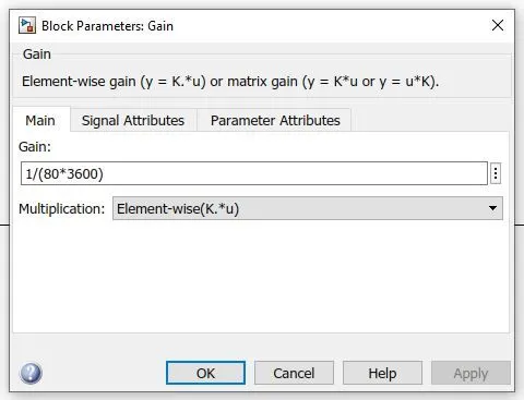
2)Gain
This block is basically used to multiply or divide the signal coming from the rate transition block.In this case, the block is going to divide the current signal with the ampre rating of the battery which is 80Ah and 3600 ( to convert seconds into hours).
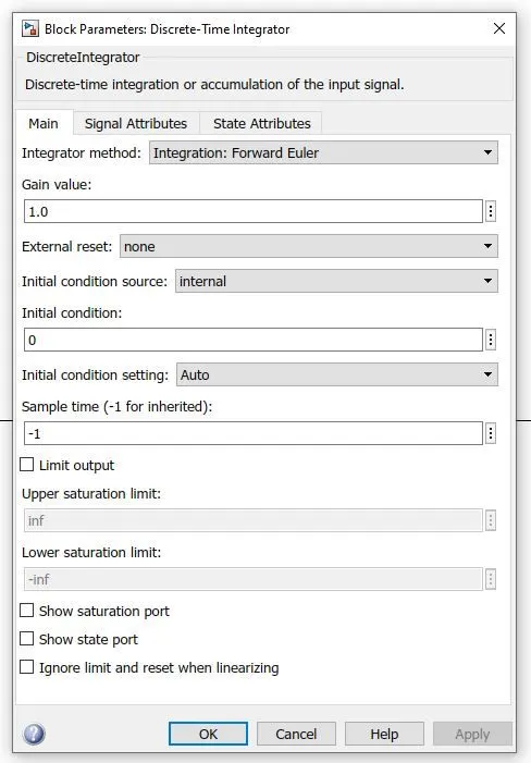
3)Discrete Time Integrator
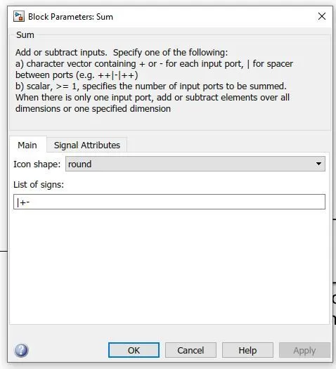
4)Sum
Google Drive Link For Electric Car Simulink File: https://drive.google.com/file/d/1Smqvr-6NaL14BEpx3-SiCo18sswhBvfM/view?usp=sharing
A Complete Simulink Block Diagram: -
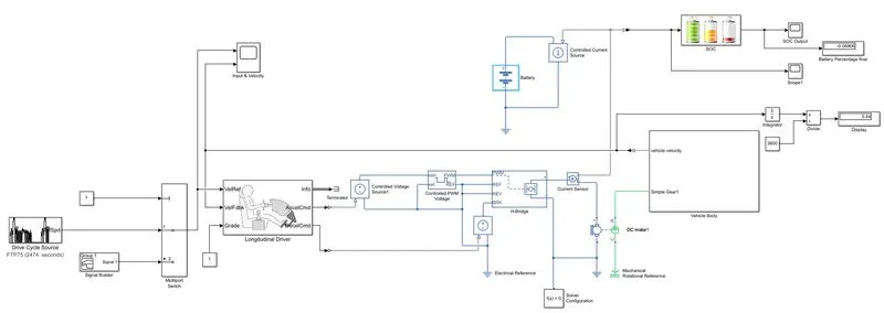
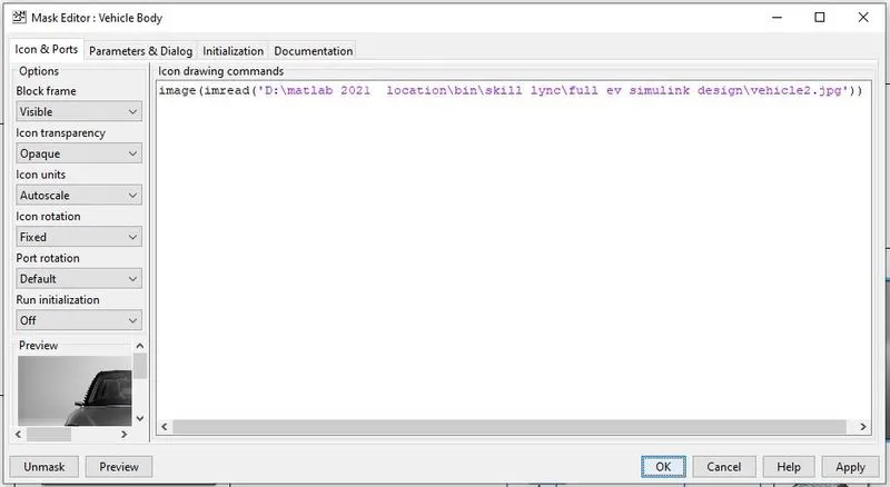
In order to improve the overall aesthetics of the Simulink model we are now adding the images to subsystems by right click on the subsystem select the mask option and edit mask. Here we have to enter the image properties as shown below.
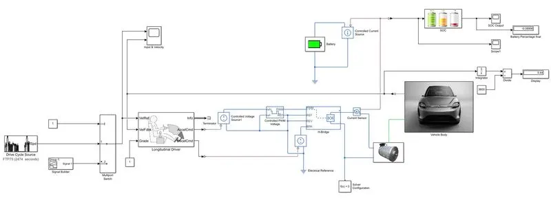
Then the final simulink diagram is shown below.
Explanation of the Simulink Model of Electric car: -
A Duty cycle Source consist a set data which shows how the vehicle velocity changes with respect to time in seconds is given as an input to the Simulink model of electric car.The selected data is FTP75 which can be seen in the scope (input & velocity). This Duty cycle is given to the vehicle reference (VelRef) port of longitudinal driver block.
The velocity of the vehice body is a physical value which is converted into simulink signal with the help of PS-simulink converter and given to the VelFdbk — Longitudinal vehicle velocity port of longitudinal Driver.The gradability of the road is consider '1' hence we provided grade port of longitudinal driver with constant '1'. The info port is teminated by using the terminator block.
The acceleration commands (accelcmd) from the longitudinal driver is given to controlled voltage source1. Here the changes in the acceleration will effect the controlled PWM voltage which changes the H-bridge parameters.This will increase the current supplied to the motor and the vehicle starts to accelerate.similarly a decelaration command (decelCmd) of the longitudinal port is connected to the controlled voltage source and it is connected to the BRK port of H-Bridge which provides braking action to the motor.A solver configuration is connceted to the motor negitive terminal.
The H-bridge provides the required power to the DC Motor for the acceleration of electric vehicle.The amount of current supplied to the motor is sensed by the current sensor and provides the signal to the controlled current source which is connected to the main battery and current taken by the motor is shown in the scope1.
The SOC (State of Charge) provides the level of charge of an electric battery relative to its capacity. The units of SoC are percentage points (0% = empty; 100% = full). The SOC Output scope provides the graph of SOC.
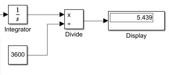
For the distance measurement in kilometer the value of velocity is integrated (1/s) and divided with time (3600).The simulink blocks used are shown below.
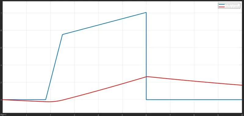
Graphs for selecting MultiPort Switch 2:-
The Input from the Signal builder and it's respective velocity is obtained in the scope input & Velocity is shown below.
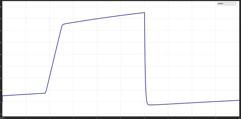
The Current Drawn by the motor is shown below.
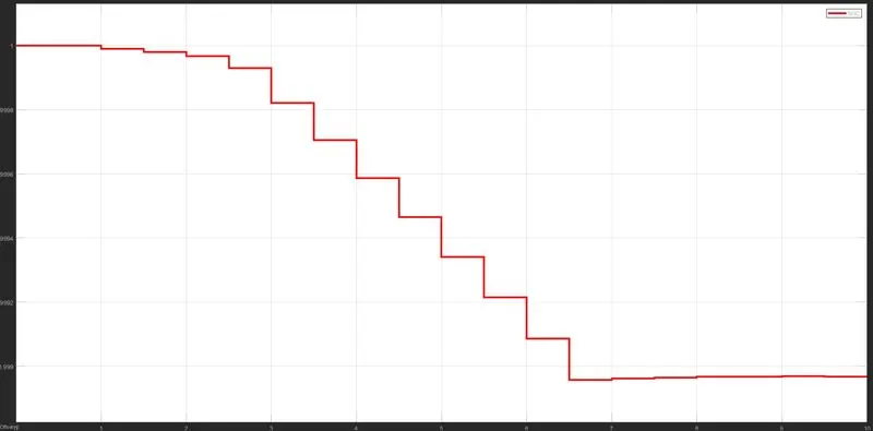
The SOC graph is shown below.
Conclusions for selecting MultiPort Switch 2 :-
1)As the velocity of vehicle is increasing the current drawn from the battery is also increasing.
2) for 10sec of signal builder input the SOC of the battery is changed from 100% to 99.9%.
Graphs for selecting MultiPort Switch 1:-
The Input from the Duty Cycle with a run time of 2474sec and it's respective velocity obtained in the scope input & Velocity is shown below.
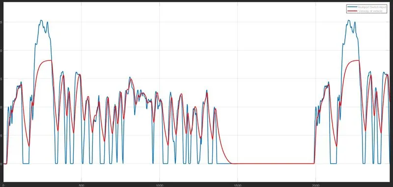
The Current Drawn by the motor is shown below.
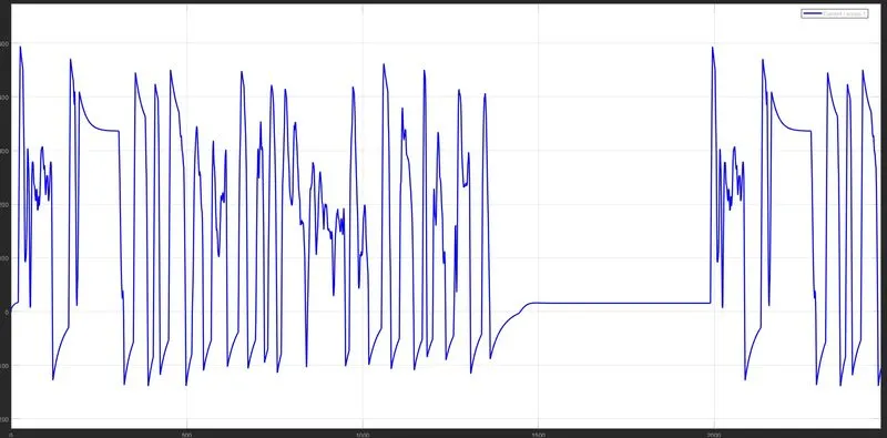
The SOC graph is shown below.
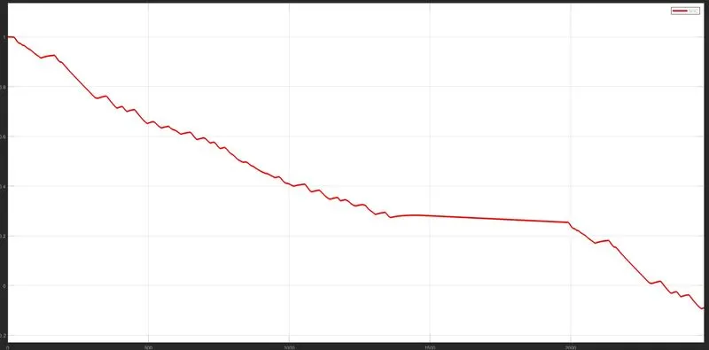
Conclusions for selecting MultiPort Switch 1 :-
1) A large number of spikes are their in the current graph is due to sudden variation of velocity provided by the duty cycle.
2)The small up's in SOC graphs are due to regenerative action where the battery is charging.
3)The SOC graph starts decreasing from 1 (100%) to -0.089 (-8.9%).Here the negitive value indicates that the battery capacity used was not sufficient and I have to increase the battery capacity by 9%. The simulink is a powerful tool which helps us to simulate the full electric car design and find the errors before manifacturing of the physical model.Hence in the real world it saves lots of time and money.