Week -2
1.SIMULINK MODEL OF DOORBELL USING SOLENOID BLOCK
OBJECTIVE:-
To understand the detailed analysis of doorbell using solenoid block with MATLAB SIMULINK.
INTRODUCTION:-
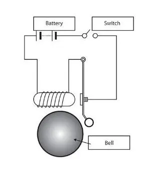
SOLENOIDS:- A solenoid is a type of electromagnet, the purpose of which is to generate a controlled magnetic field through a coil wound into a tightly packed helix. The coil can be arranged to produce a uniform magnetic field in a volume of space when an electric current is passed through it.
In engineering, the term may also refer to a variety of tranceducer devices that convert energy into linear motion. In simple terms, a solenoid converts electrical energy into mechanical work. The term is also often used to refer to a solenoid valves, an integrated device containing an electromechanical solenoid which actuates either a pneumatic or hydraulic valve, or a solenoid switch, which is a specific type of relay that internally uses an electromechanical solenoid to operate an electrical switch; for example, an automobile starter solenoid or linear solenoid. solenoid bolts, a type of electromechanical locking mechanism, also exist. In electromagnetic technology, a solenoid is an actuator assembly with a sliding ferromagnetic plunger inside the coil. Without power, the plunger extends for part of its length outside the coil; applying power pulls the plunger into the coil. Electromagnets with fixed cores are not considered solenoids.
DOORBELL CIRCUIT DIAGRAM:-
SIMULINK BLOCKS FOR DOORBELL:-
- SIGNAL BUILDER
- SCOPE
- SIMULINK-PS CONVERTER
- PS-SIMULINK CONVERTER
- BATTERY
- SWITCH
- SOLENOID
- ELECTRICAL REFERENCE
- MECHANICAL TRANSLATIONAL REFERENCE
- IDEAL TRANSLATIONAL MOTION SENSOR
- SOLVER CONFIGURATION
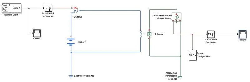
SIMULINK BLOCK DIAGRAM OF DOORBELL:-
DESCRIPTION:-
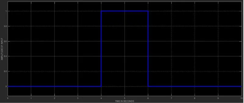
- Signal builder with amplitude=1 and time duration of 2 sec is given to simulink- PS converter which converts the signal into physical input for a duration of 2 sec.which is given as an input to the switch.
- The solenoid operates for duration of 2 sec is observed with the help of ideal translational motion sensor; the physical output is converted into signal output with the help of PS-simulink converter.
- The output graph can be observed in scope.
NOTE: - In order to execute the program properly the following must be connected
-
For the mechanical system a solver configuration is to be connected.
-
For electrical circuits a electrical reference has to be connected and for mechanical circuit a mechanical translational circuit has to be connected.
INPUT SIGNAL GRAPH:-
OUTPUT GRAPH:-
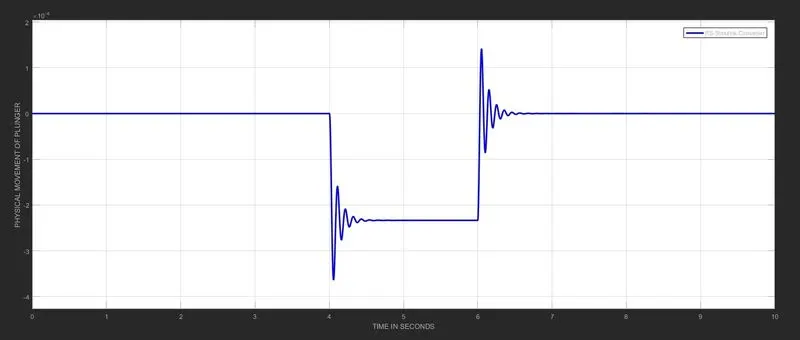
Result:- an oscillating output at 4th and 6th duration of second is observed.
2.Thermistor To Sense The Temperature Of A Heater
Objective:-
A detail analysis on sensing the heater temperature using a Thermistor for turn on/off, with
temperature source: 20°C (293K) from 0 to10 seconds
27°C (300K) from 10 to 30 seconds
23°C (296K) from 30 to 50 seconds
Fan conditions: ON if the temperature above 25 °C, OFF otherwise.
INTRODUCTION:-
A Thermistor is a resistance thermometer, or a resistor whose resistance is dependent on temperature. The term is a combination of “thermal” and “resistor”. It is made of metallic oxides, pressed into a bead, disk, or cylindrical shape and then encapsulated with an impermeable material such as epoxy or glass.
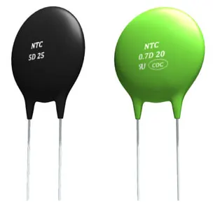
Thermistor Types
There are two types of thermistors. NTC or Negative Temperature Coefficient thermistors, and PTC or Positive Temperature Coefficient thermistors. The difference is that NTC thermistors exhibit a decrease in resistance as body temperature increases, while PTC thermistors exhibit an increase in resistance as body temperature increases.
Applications for NTC and PTC Thermistors include:
- Temperature Compensation
- Temperature Measurement
- Temperature Control
- Inrush Current Limiting
Simulink blocks with parameters are as follows:
|
Serial .No |
Block Names |
Parameters |
|
1. |
Signal builder |
20°C (293K) from 0 to10 seconds 27°C (300K) from 10 to 30 seconds 23°C (296K) from 30 to 50 seconds |
|
2. |
Current source |
DC current: 10 A |
|
3. |
Thermistor |
Nominal resistance R0 at reference temperatureT0: 1000 Ohm Characteristic temperature constant B: 3500 K Reference temperature T0: 298.15 K |
|
4. |
Resistor |
Resistance : 10 Ohm |
|
5. |
Switch |
Threshold: 9.902 |
|
6. |
Dc Motor |
Armature resistance: 3.9 Ohm Armature inductance: 1.2e-5 H Back-emf constant: 7.2e-5 V/rpm |
|
7. |
Constant |
Constant value: 1 & 0 |
|
8. |
Simulink-PS Converter |
|
|
9. |
PS-Simulink Converter |
|
|
10. |
Scope |
|
|
11. |
Controlled voltage source |
|
|
12. |
Ideal Rotational Motion Sensor |
|
|
13. |
Electrical Reference |
|
|
14. |
Mechanical rotational reference |
|
|
15. |
Solver Configuration |
|
|
16. |
Display |
Simulink block diagram for sensing the heater temperature using a Thermistor:-
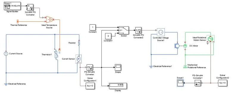
Description:-
- A signal builder is used to generate a signal with the parameter 20°C (293K) from 0 to10 seconds, 27°C (300K) from 10 to 30 seconds and 23°C (296K) from 30 to 50 seconds.
- The generated signal is given to Thermistor by converting it into a physical temperature with the help of simulink-PS converter.
- The current source supplies a constant current of 10A to a parallel circuit of resistance and thermistors.
- As the temperature varies at thermistor, its resistance also varies then current flowing in the thermistor also varies. Hence the current received by the resistor is also varies which can be detected by current sensor.
- In order to ON the fan at 25°C (298K) , The switch requires a threshold of 9.902 which can be determined by giving a constant of 298 as an input for the below figure.
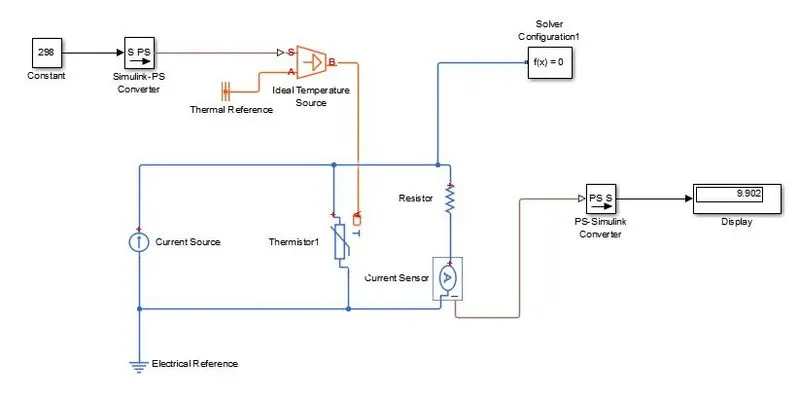
- The switch response is a digital ‘0 or1’ signal it is converted into a physical switch with the help of simulink-PS converter.
- The switch output is given to controlled voltage source which provides a constant voltage to a DC motor which acts as a fan as shown in figure. The output response of DC motor is obtained with the help of ideal rotational sensor.
INPUT RESPONSE:-
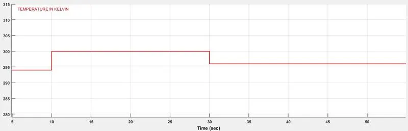
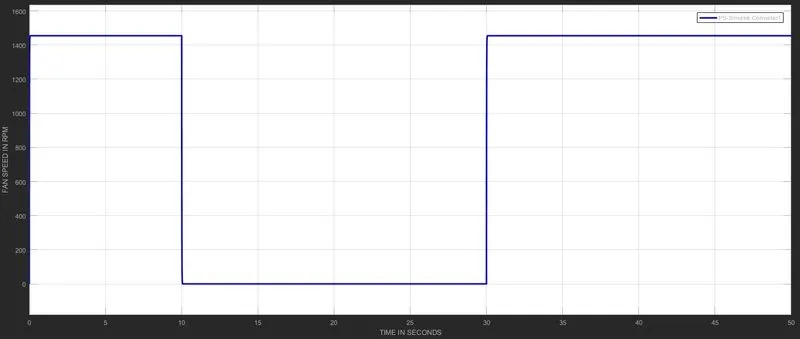
OUTPUT GRAPH:-
CONCLUSION:-
During the time interval 10 to 30 sec the fan speed is reduced to zero rpm. Therefore the fan is turned OFF for 27°C and for the remaining temperatures (20°C & 23°C) the fan is rotating with 1450 rpm.