Project 1 Mechanical design of battery pack
Objective:- To Create a battery pack of 18KWh using the Cells: ANR26650M1-B
Introduction to Li-ion Cell (ANR26650M1-B):-
In March of 2018 LitiumWerks acquired the rights to produce the Cell ANR26650M1-B which is a high power Lithium Iron Phosphate (LiFePO4) cell formerly known as A123 cell. It is a 3.3Volts,2.5Ah Cylindrical Battery.
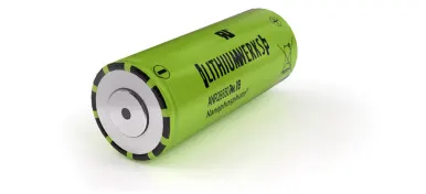
Lithium Werks’ 26650 cells are capable of delivering very high power due to its use of patented Nanophosphate ® battery technology. Based on lithium iron phosphate chemistry (LiFePO4), the cells are inherently safe over a wide range of temperatures and conditions. Whether the application requires outstanding cycle life or stable float reliability, the Lithium Werks’ 26650 cells are suitable for a wide variety of power, pulse, or stand-by applications.
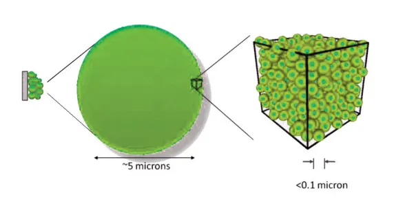
Nanophosphate® battery technology offers stable chemistry, faster charging, consistent output, excellent cycle life and superior cost performance. It provides the foundation for safe systems while meeting the most demanding customer requirements. Multiple layers of protection are employed at the chemistry, cell and system level to achieve an energy storage solution with superior safety and abuse tolerance compared to metal oxide lithium-ion chemistries.
Its Application:-
- Energy storage
- Uninterruptible Power Supplies
- Communication technologies
- Aerospace
- Electrified mobility devices
- Industrial equipment
- Medical devices
- Toys
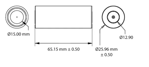
Dimentions:-
EV Design- Battery Calculation:-
Assumptions:-
1)Battery Energy = 18KWh
2)Total Voltage of Battery Pack = 600V
3)Number of Cells (N)= Energy/ (Nominal Voltage*Capacity)
N=18000/(3.3*2.5)
=>N=2182
So, In order to create a battery pack of 18KWh we need 2182 Number of cells.Now we have decide the series-parallel configuration of Battery.
Series (Ns) : No. of series cells required to produce a 600V is (Ns)= Required Voltage/Nominbal Voltage of one cell
Ns=600/3.3
=>Ns=182
Parallel (Np): Here 182 cells are connected in series to produce a 600V but this 182 cells module will generate only 2.5Ah whiceh means it will create a battery pack of 600*2.5=1.5KWh. For creating a 18KWh battery these 182 cells should be connected in parallel. Therefore Np (No. of parallel cells)=Total cells/ Ns.
Np=2182/182
=>Np=12
3)Battery Capacity= Np*Cell capacity
=12*2.5
=30Ah
4)Weight of Battery Pack(W):-
weight of each cell =76grams
Total weight of battery pack(W)= Weight of cell*No of Cells+ weight of accessories
=76*2182g+5kg
=165.83+5
=170.83Kg
Cell Specifications in detail:
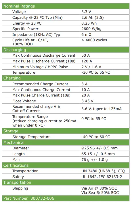
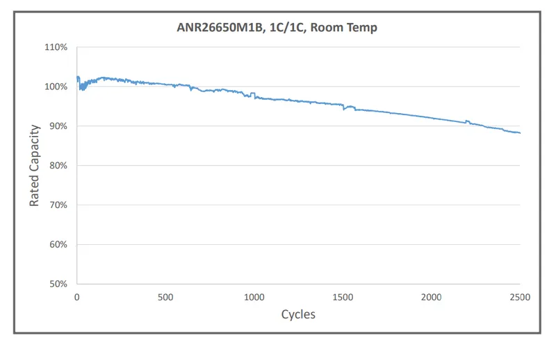
- Graph demonstrating cells rated Capacity Vs No of cycles is shown below.
-
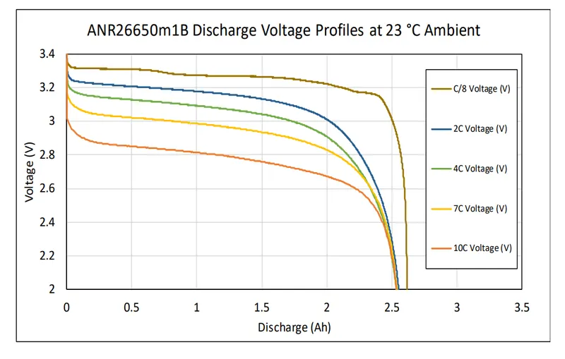
Graph showing voltage (V) Vs Discharge(Ah) under the ambient conditions which is at 23°C is shown below.
A standard automotive battery pack consists of hundreds, even thousands, of individual Li-ion batteries that are connected in series or parallel in order to achieve the required power and energy. Additionally, there is an increasing requirement for manufacturing of battery packs, reflecting the increased demand for this energy storage technology, which is predicted to grow as the volume of automotive product using it develops.
In general, an automotive battery pack can be hierarchically decomposed into three levels: (a) emphcell level: an individual battery cell is primarily composed of positive and negative electrodes, separators, electrolyte, and case; (b) module level: a collection of multiple cells generally connected in series and parallel, encased in a mechanical structure; and (c) pack level: a battery pack is assembled by connecting modules together, either in series or parallel, with sensors and controllers, and then is encased in a housing structure. Typically, design and construction of an automotive Li-ion battery pack, as illustrated in below Figure.
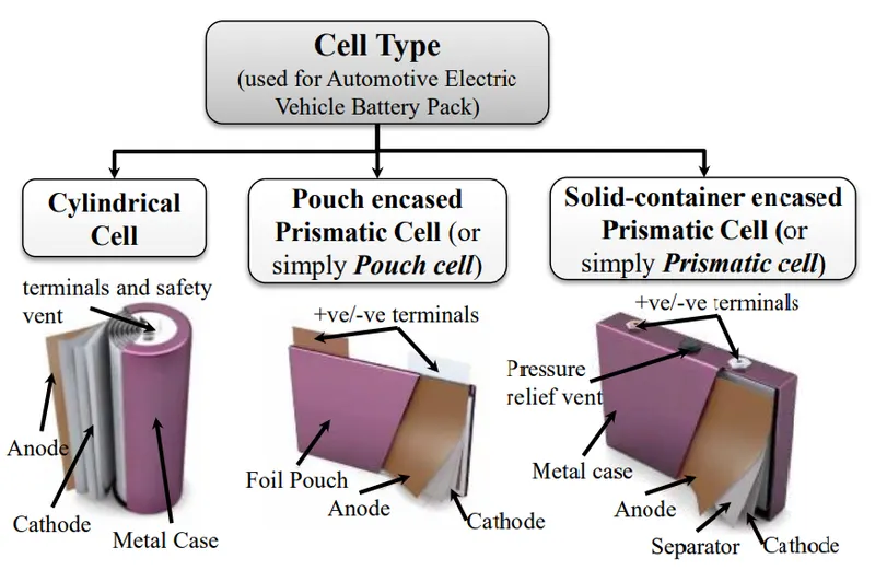
Figure 1. Battery packs of electric vehicles, and hybrid or plug-in hybrid electric vehicles (EVs/HEVs/PHEVs)
Relying on the geometry and form factor, lithium-ion cells are manufactured as (i) cylindrical cells; (ii) pouch encased prismatic cell (typically called a pouch cell); and (iii) solid-container encased prismatic cell (typically called a prismatic cell). Choice of joining methods is largely based on the type of cell used, and subsequently, to satisfy electrical, thermal, and mechanical key criteria which can be summarised as follows:
• Electrical and thermal challenges: (i) Producing joints with low electrical resistance—lower electrical resistance at the joint results in low energy loss, low heat generation, and subsequently, lower joint temperature increase during charging and discharging. (ii) Producing joints with low thermal input—low thermal input is preferable, especially when joining with fusion type welding processes, as exposing the cell to high heat may melt or disturb the safety vent, compromise seals,
or cause internal shorting. (iii) High thermal fatigue resistance—thermal fatigue resistance of battery interconnects is an important criterion for long-term durability and reliability performance.
• Material and metallurgical challenges: (i) Compatibility for dissimilar materials joining—dissimilar materials may create intermetallic layers, which are not preferred because of their higher electrical resistance and brittle nature compared with parent materials. Therefore, joints with low intermetallic is preferable. (ii) Variability of materials and surfaces—highly conductive and reflective materials, any surface coatings or oxide layers, joint stack-ups (especially varying thicknesses and/or multiple sheets) also need to be overcome for satisfactory joints.
• Mechanical challenges: (i) Durable joint strength—the joint area/nugget size that can be achieved by the joining methods should have satisfactory joint strength with low strength variability. (ii) Avoid mechanical and vibrational damage when joining—excessive deformation of, or transmission of vibration into, the cell may damage internal connection. Precautions must be taken to avoid these as induced residual stress or vibrational energy may be released and cause joint failure.
1)Ultrasonic Welding or Ultrasonic Metal Welding (UMW):-
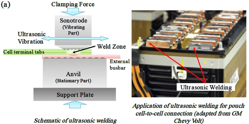
It is one of the most commonly used joining methods for battery systems manufacturing and has been applied to a wide range of metals and thin metal films (e.g., foils). It utilizes high frequency ultrasonic vibration, typically 20 kHz or above, to join substrate materials by creating solid-state bonds under a clamping pressure. In principle, high frequency relative motion creates progressive shearing and plastic deformation between mating interfaces and produces an atomic bond at elevated temperature (i.e., typically at 0.3 to 0.5 times the absolute melting temperature of the substrate materials). However, it needs two-sided access, as shown in Figure; one side uses an anvil to support the parts to be joined, and the other side a sonotrode that passes ultrasonic energy to the assembly. Ultrasonic welding is applied for joining of multiple thin foils, dissimilar materials, or highly conductive materials (e.g., Al, Cu, or others), especially for pouch cells. However, it may not be suitable for terminal-to-busbar joints of cylindrical or prismatic cells as vibration under pressure may damage structural integrity. UMW has been used for various EVs/PHEVs, including Nissan LEAF, General Motors Chevrolet-Volt, Spark, and Bolt.
2)Resistance Spot/Projection Welding:-
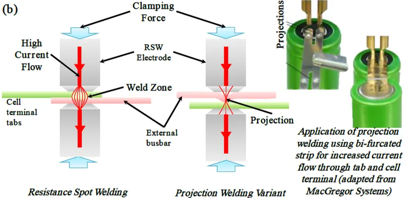
It works on the principle of electrical resistance at the mating surfaces when high current passes through them, creating localised heating and fusion of materials under pressure. Resistance spot welding is used to join different tab materials, up to 0.4 mm thickness, which are being used for battery connections, including steel, nickel (Ni), copper (Cu), and aluminium (Al). However, RSW of Al and Cu tabs is difficult because of high electric and thermal conductivity and in particular, the presence of an oxide layer on the surface of Al. To overcome these challenges, projection welding, a variant of RSW, shows a significant improvement, where projection on tabs will increase the joint quality and make welding easier. As indicated in Figure, the projections not only act as energy concentrators for the weld, but also greatly increase electrode lifetimes, because a flat-end RSW-electrode can be used instead of a domed one. In spite of easy automation and good quality control, RSW has challenges when applied to battery welding because of RSW-electrode sticking (i.e., pick-up of material on the electrode tips), highly conductive materials, dissimilar materials having different melting temperatures, and the smaller weld nugget experiencing heat generation during charging–discharging because of the increased current density.
3) Micro-TIG or Pulsed Arc Welding (PAW):-
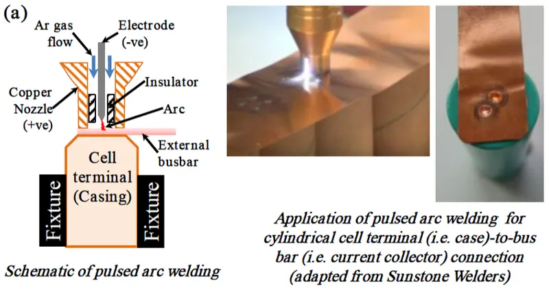
It also known as micro-TIG welding, uses a pulsed TIG arc without filler wire to join thin materials by localised fusion, see Figure. The arc pulse has a very short duration, in tens of milliseconds, such that heat input is much less than in conventional TIG welding, and can be used for welding dissimilar materials. However, even with a significantly reduced heat input, it is still crucial to control the welding parameters to avoid overheating of the battery. PAW is suitable for nickel, copper, or steel tabs and copper bus bars. Al tabs and bus bar joining using PAW is difficult and not preferable (because of the typical direct current (DC)–electrode negative configuration). Alternating current (AC) PAW is more typically used for Al welding, this is because of the cleaning mechanism, which breaks down the electrically resistive aluminium oxide skin of aluminium alloys. AC pulsed arc welding has not yet been commercially developed for micro-joining applications. For copper tab to copper bus bar welding, micro-TIG can produce a single spot nugget in diameter up to 4 mm. There is no report of the application of pulsed arc welding for joining of existing EV or HEV battery packs.
4)Ultrasonic wedge bonding (UWB):-
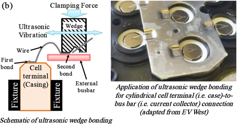
It is a joining technique typically used for electronic connections between circuit boards or electronic chips. During the welding process, a small (typically <500 µm in diameter) wire (of Al, Cu, or Au) is fed through a welding head; the welding head applies ultrasonic vibration and pressure forcing the wire against the welding target, for example, the battery terminals or bus bar, as shown in below Figure. The main mechanism of UWB is cleaning of mating surfaces and bringing surfaces to the distance required for atomic bonding to create the connections, although other mechanisms, such as inter-diffusion of wire into the mating surface and mechanical interlocking, also contribute to the joining process. UWB can be used for joining of dissimilar materials and the bonded wire can be used as a fuse to protect the battery pack against extreme thermal and mechanical impact or internal defects. However, because transfer of ultrasonic energy into the material to be joined is critical for welding, any significant lateral movement of the welding substrate will be detrimental as it will decrease the vibration amplitude, thereby diminishing the power of the welding operation. Consequently, the cells and the bus bar in the battery module need to be fixed rigidly to allow the technology to be applied. In many cases, adhesives or glues have to be used to enhance the rigidity of cells.
5)Clinching or micro-clinching:-
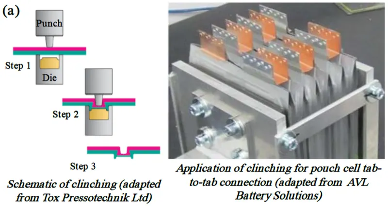
It is a mechanical interlocking mechanism of sheet metal parts, especially used for automotive body-in-white, domestic appliances, or electronics joining applications. Clinching is a joining process in which a mechanical interlock (i.e., local deformation without use of any additional joining elements) is created by a tooling set (a punch and a die), as shown in below Figure. Clinching is a simple technique for point joining of metal sheets typically from 0.2 mm to 4 mm thick, to a total joint thickness of about 6 mm. Using the clinching, tab-to-tab joints are feasible. The feasibility of clinching as an alternative method of joining for pouch cell tab joining has been reported. Clinching may not be feasible for cylindrical/prismatic cells joining as access to the both sides of the assembly is required. Further, clinch joints are prone to becoming loose under vibration, moisture ingress, and so on.
6) Soldering:-
Joining of dissimilar materials using this method is an established and tested technology within the electronics industry. Soldering of a tab to a terminal of a cylindrical cell may be feasible. Soldering directly to a cell is not recommended as it is easy to melt or disturb the safety vent, compromise seals, or cause internal shorting if the heat is too high (i.e., heat input is the key soldering parameter). Further, it is feasible to solder pouch cell tabs if additional filler metal is used between the tabs. Special aggressive fluxes are required for joining aluminium, which is typically considered unattractive because of the potential for corrosion, reduction of joint strength under vibration, and creating debris. Therefore, soldering is unlikely to be of widespread interest for battery joining applications.
7) Laser welding:-
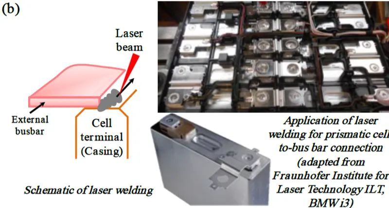
It uses a focused laser beam as a point source of energy to create localised heating to join parts together. Because of the small cross section of the laser beam and its energy concentration, narrow and deep welds can be made with a high welding speed. Also, because of the narrow welds and high welding speed, the process generates a low level of heat in the assembly during welding, which is important for battery tab welding, as the chemicals inside the batteries are very heat sensitive. A schematic of fillet laser welding and application for prismatic cell-to-bus bar joining are shown in below Figure. When welding a tab to a terminal, generally, the tab should be thinner than the battery cell casing terminal. Process parameters need to be controlled to provide weld strength and conductivity without penetrating the battery case/can. Other applications include sealing of the battery casing for prismatic cells and joining of tab-to-bus bar and bus bar-to-bus bar. As the weld pool from laser welding is very small, it has a very small gap tolerance, subsequently, during tab welding, it may be necessary to clamp the tab to the battery. For oxidization sensitive materials, such as Al, gas shielding is also required.
8) Magnetic pulse welding:-
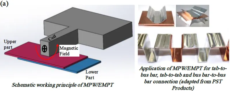
It is a solid-state welding process that uses a magnetic pulse to accelerate one part into another, creating a high speed (up to 500 m/s) collision that results in bonding. The advantages of this process include low heat input, high joint strength, and the capability to join dissimilar materials. However, as the technology has the potential to create an induced current in the cell, because of the pulsed magnetic field necessary for the joining process, damage may occur, which renders it unsuitable for battery joining. However, MPW/EMPT has the potential for joining pouch cell tab-to-tab or tab-to-bus bar. Furthermore, detailed investigation is required as induced eddy currents may affect the electrochemistry/physical parts (e.g., potential cracks or internal joining between current collectors, which lead to battery internal short-circuit) of the pouch cell. To mitigate the risk of damaging the pouch cell or module sensors, a specially designed weld head and shielding plate may be required during welding. To mitigate the risk of damaging the pouch cell or module sensors, a specially designed weld head and shielding plate may be required during welding.
9) Mechanical Assembly: -
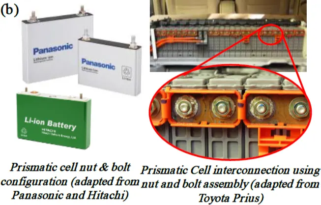
Various mechanical fastening methods can be used for battery joining, including nut and bolt, spring clasp, screws or snap-fits, and so on. Nut and bolt joints may be either physically distinct nut and bolt assemblies or a threaded feature, for example, electrode and nut. For battery module level connections, nut and bolt joints are mainly limited to prismatic cells, as shown in Figure, and have been used to join electric and hybrid vehicle battery modules. Another example of using mechanical fastening is spring loaded prismatic cells into a custom designed container. Permanent joining, such as welding, may not be suitable for large pack level joining because of battery maintenance and service concerns. Consequently, mechanical nut and bolt assembly has been widely adopted at the pack level.
Summary of Joining Technologies:-
|
Sl.No |
Joining Technology |
Advantages |
Disadvantages |
Issues and Concerns |
|
1) |
Ultrasonic welding |
Fast process, high strength and low resistance, able to join dissimilar materials, low energy consumption |
Only suitable for pouch cells, two sided access, slow joining |
Access of anvil and sonotrode needs to be well designed |
|
2) |
Resistance spot/projection welding |
Fast process, low cost, good quality control, easy automation |
Difficult for highly conductive and dissimilar materials |
Difficulty to produce large joints, joining of more than two layers |
|
3) |
Micro-TIG/pulsed arc welding |
Fast process, low cost, good quality control, easy automation |
High thermal input and heat affected zone, porosity |
Difficult to join Al to steel |
|
4) |
Ultrasonic wedge bonding |
Fast process, acting as fuses, able to join dissimilar materials, low energy consumption and easy automation |
Only suitable for small wires, low wire and joint strength |
Clamping of the batteries is critical |
|
5) |
Micro-Clinching |
Cold process, no additional part, clean process, able to join dissimilar materials |
Only suitable for pouch cells, two side access, slow joining |
Loosening under vibration, moisture ingress |
|
6) |
Soldering |
Joining dissimilar materials, wide spread in electronics industry |
High heat, fluxes required |
Joint strength, debris, neutralisation of fluxes |
|
7) |
Laser welding |
High speed, less thermal input, non-contact process, easy Automation |
High initial cost, additional shielding system may required |
Need good joint fit-up (intimate contact), high reflective materials |
|
8) |
Magnetic pulse welding |
Solid state process, able to join dissimilar materials, high joint strength, dissimilar materials |
Potential large distortion, rigid support required |
Possibility of eddy current passing through the cells |
|
9) |
Mechanical assembly |
Easy dismounting and recycling, easy repair, cold process |
Additional weight, high resistance, expensive |
Potential mechanical damage and go loose |