Week-7 Challenge: DC Motor Control
Aim: - Controlling of DC Motor in MATLAB software.
Objective: -
- A) Explain a MATLAB demo model named ‘Speed control of a DC motor using BJT H-bridge’. B)Comment on the armature current shoot-up from the scope results. C)Refer to the help section of ‘The Four-Quadrant Chopper DC Drive (DC7) block’. Compare it with the H-bridge model.
- Develop a 2-quadrant chopper & explain the working of the same with the relevant results. (Refer to article - Multiquadrant operation of motor )
Explain in a brief about operation of BLDC motor.
Introduction to DC Motor control with Power Electronic Devices: -
Power electronics is the application of solid-state electronics to the control and conversion of electric power.
Basic Power Electronic switches which are used to control DC motors are as follows
1) Thyristors (SCR)
2) Power MOSFET
3) IGBT
4) Power BJT
1) Thyristors: - The name Thyristor is derived by a combination of the capital letters from THYRattron and transISTOR. It consists of three p-n junctions and two stable states, an ON-state and an OFF-state. It can change its state from one to another.
Thyristors can control a relatively large amount of power and voltage with a small device, they find wide application in control of electric power, ranging from light dimmers and electric motor speed control to high-voltage direct-current power transmission. Thyristors may be used in power-switching circuits, relay-replacement circuits, inverter circuits, oscillator circuits, level-detector circuits, chopper circuits, light-dimming circuits, low-cost timer circuits, logic circuits, speed-control circuits, phase-control circuits, etc.
Silicon Controlled Rectifier (SCR)
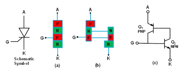
SCR is the oldest and first member of the thyristor family. It is called SCR because; silicon is used for its construction and its operation as a rectifier (very low resistance in forward construction and very high resistance in the reverse direction) and can be controlled.
There are three modes of operation for an SCR depending upon the biasing given to it:
a) Forward blocking mode (off state) b) Forward conduction mode (on state) c) Reverse blocking mode (off state)
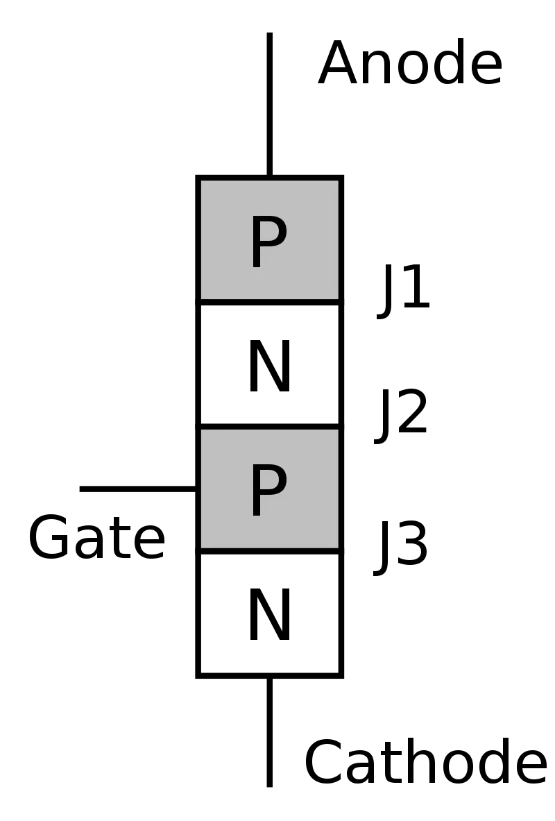
Forward blocking mode
In this mode of operation, the anode (+) is given a positive voltage while the cathode (−) is given a negative voltage, keeping the gate at zero (0) potential i.e., disconnected. In this case junction J1and J3 are forward-biased, while J2 is reverse-biased, allowing only a small leakage current from the anode to the cathode. When the applied voltage reaches the breakover value for J2, then J2 undergoes avalanche breakdown. At this breakover voltage J2 starts conducting, but below breakover voltage J2 offers very high resistance to the current and the SCR is said to be in the off state.
Forward conduction mode
An SCR can be brought from blocking mode to conduction mode in two ways: Either by increasing the voltage between anode and cathode beyond the breakover voltage, or by applying a positive pulse at the gate. Once the SCR starts conducting, no more gate voltage is required to maintain it in the ON state. The minimum current necessary to maintain the SCR in the ON state on removal of the gate voltage is called the latching current.
There are two ways to turn it off:
- Reduce the current through it below a minimum value called the holding current, or
- With the gate turned off, short-circuit the anode and cathode momentarily with a push-button switch or transistor across the junction.
Reverse blocking mode
When a negative voltage is applied to the anode and a positive voltage to the cathode, the SCR is in reverse blocking mode, making J1 and J3 reverse biased and J2 forward biased. The device behaves as two reverse-biased diodes connected in series. A small leakage current flow. This is the reverse blocking mode. If the reverse voltage is increased, then at critical breakdown level, called the reverse breakdown voltage (VBR), an avalanche occurs at J1 and J3 and the reverse current increases rapidly. SCRs are available with reverse blocking capability, which adds to the forward voltage drop because of the need to have a long, low-doped P1 region. Usually, the reverse blocking voltage rating and forward blocking voltage rating are the same. The typical application for a reverse blocking SCR is in current-source inverters.
2) Power MOSFETs :-
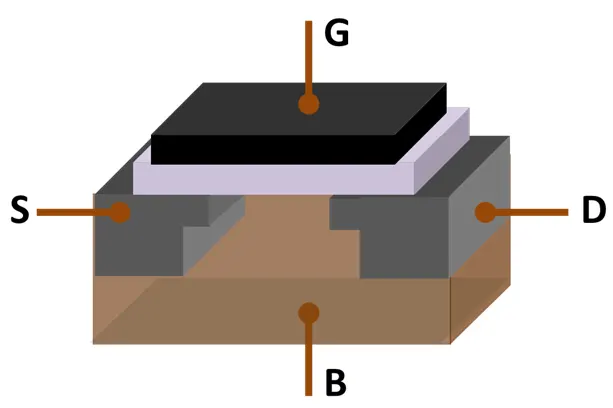
The power MOSFET is the most widely used power device in the world. Advantages over bipolar junction transistors in power electronics include MOSFETs not requiring a continuous flow of drive current to remain in the ON state, offering higher switching speeds, lower switching power losses, lower on-resistances, and reduced susceptibility to thermal runaway. The power MOSFET had an impact on power supplies, enabling higher operating frequencies, size and weight reduction, and increased volume production.
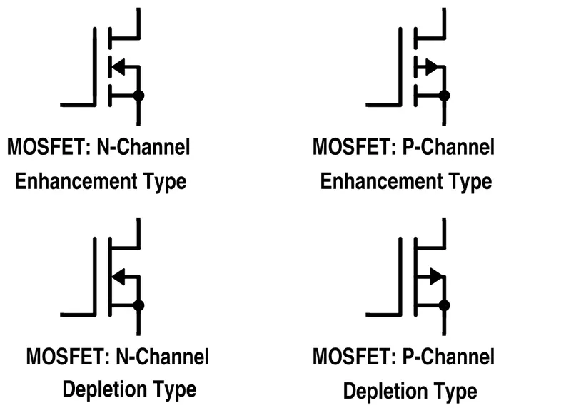
Switching power supplies are the most common applications for power MOSFETs.They are also widely used for MOS RF power amplifiers, which enabled the transition of mobile networks from analog to digital in the 1990s. This led to the wide proliferation of wireless mobile networks, which revolutionized telecommunication systems. The LDMOS in particular is the most widely used power amplifier in mobile networks, such as 2G, 3G,4G, and 5G. They are widely used for automotive, industrial and communications systems in particular. Power MOSFETs are commonly used in automotive electronics, particularly as switching devices in electronic control units, and as power converters in modern electric vehicles. The insulated-gate bipolar transistor (IGBT), a hybrid MOS-bipolar transistor, is also used for a wide variety of applications.
3)IGBT
An insulated-gate bipolar transistor (IGBT) is a three-terminal power semiconductor device primarily used as an electronic switch, which, as it was developed, came to combine high efficiency and fast switching. It consists of four alternating layers (P–N–P–N) that are controlled by a metal–oxide–semiconductor (MOS) gate structure.
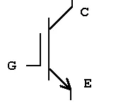
Although the structure of the IGBT is topologically the same as a thyristor with a "MOS" gate (MOS-gate thyristor), the thyristor action is completely suppressed, and only the transistor action is permitted in the entire device operation range. It is used in switching power supplies in high-power applications: variable-frequency drives (VFDs), electric cars, trains, variable-speed refrigerators, lamp ballasts, arc-welding machines, and air conditioners.
Since it is designed to turn on and off rapidly, the IGBT can synthesize complex waveforms with pulse-width modulation and low-pass filters, so it is also used in switching amplifiers in sound systems and industrial control systems. In switching applications modern devices feature pulse repetition rates well into the ultrasonic-range frequencies, which are at least ten times higher than audio frequencies handled by the device when used as an analog audio amplifier. As of 2010, the IGBT is the second most widely used power transistor, after the power MOSFET.
1)Power BJT: -
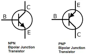
A bipolar junction transistor (BJT) is a type of transistor that uses both electrons and electron holes as charge carriers. In contrast, a unipolar transistor, such as a field-effect transistor, uses only one kind of charge carrier. A bipolar transistor allows a small current injected at one of its terminals to control a much larger current flowing between two other terminals, making the device capable of amplification or switching.
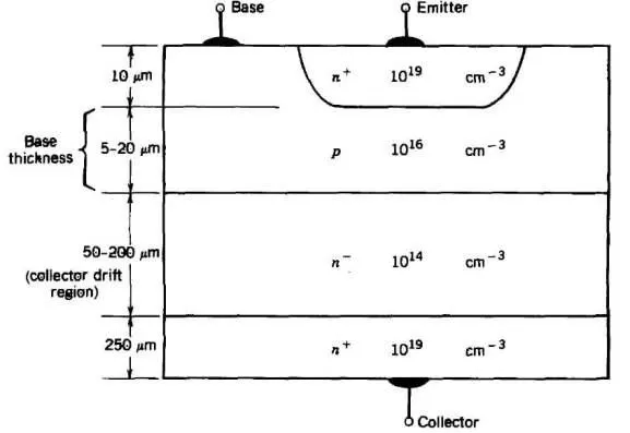
BJTs use two junctions between two semiconductor types, n-type and p-type, which are regions in a single crystal of material. The junctions can be made in several different ways, such as changing the doping of the semiconductor material as it is grown, by depositing metal pellets to form alloy junctions, or by such methods as diffusion of n-type and p-type doping substances into the crystal. The superior predictability and performance of junction transistors soon displaced the original point-contact transistor. Diffused transistors, along with other components, are elements of integrated circuits for analog and digital functions. Hundreds of bipolar junction transistors can be made in one circuit at very low cost.
1.A) MATLAB demo model named ‘Speed control of a DC motor using BJT H-bridge’.
How to Open in MATLAB:-
1)Open MATLAB software.
2)Goto Help and search for ‘Speed control of a DC motor using BJT H-bridge’.
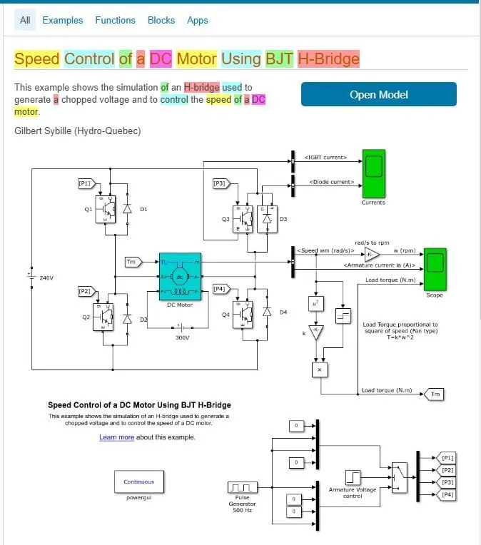
3) Select the example and click on Open Model in MATLAB as shown in the figure below.
Description
The Bipolar Junction Transistor (BJT) when used for power switching applications, operates as an IGBT. When it is conducting (BJT operating in the saturated region), a forward voltage Vf is developed between collector and emitter (in the range of 1 V). Therefore, the IGBT block can be used to model the BJT device.
The IGBT block does not simulate the gate current controlling the BJT or IGBT. The switch is controlled by a Simulink® signal (1/0). The DC motor uses the preset model (5 HP 24V 1750 rpm). It simulates a fan type load (where Load torque is proportional to square of speed). The armature mean voltage can be varied from 0 to 240 V when the duty cycle (specified in the Pulse Generator block) is varied from 0 to 100%.
The H-bridge consists of four BJT/Diode pairs (BJT simulated by IGBT models). Two transistors are switched simultaneously: Q1 and Q4 or Q2 and Q3. When Q1 and Q4 are fired, a positive voltage is applied to the motor and diodes D2-D3 operate as free-wheeling diodes when Q1 and Q4 are switched off. When Q2 and Q3 are fired, a negative voltage is applied to the motor and diodes D1-D4 operate as free-wheeling diodes when Q2 and Q3 are switched off.
Simulation
The motor starts in the positive direction with a duty cycle of 75% (mean DC voltage of 180V). At t= 0.5 sec., the armature voltage is suddenly reversed and the motor runs in the negative direction.
'Scope' shows motor speed, armature current and load torque and 'Currents' shows currents flowing in BJT Q3 and diode D3.
DC Motor specification
- supply voltage= 240 Volt
- Rated Speed = 1750 RPM
- Motor Power = 5 HP
- Field Voltage = 300 Volt
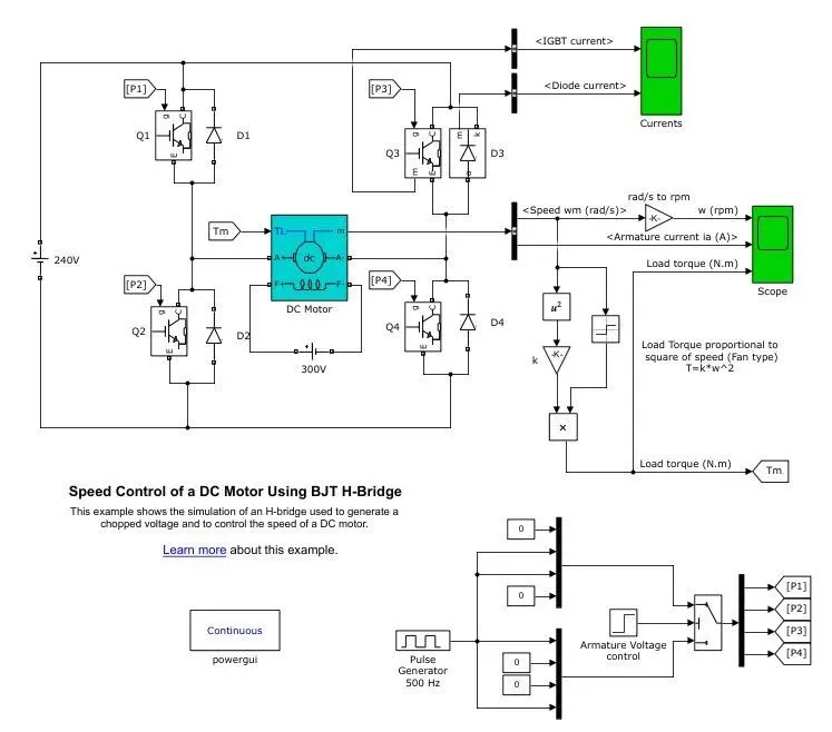
Graphs:-
- For a Duty Cycle=75% in Pulse Generator and Time duration of 1 Sec, the Scope values are shown Below .
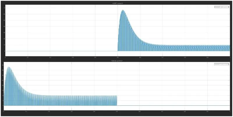
Figure 1.1
From the above figure it is clear that IGBT current is given for a duration of 0.5 to 1 Sec and Diode current is operated for a duration of 0 to 0.5 Sec. The W(RPM) and Load Torque both changed from positive to negitive values at a Duration of 0.5 sec and at that duration the armature current offers a small transient as shown in the figure below.
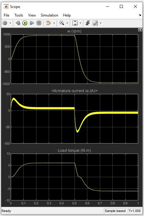
figure 1.2
ii. For a Duty Cycle=50% in Pulse Generator and Time duration of 1 Sec, the values are shown Below .
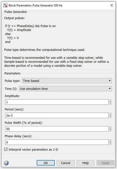
As the duty cycle decreased to 50% the IGBT and Diode currents are less than 10Amp and speed of the motor reduced from 1000RPM to less than 500RPM
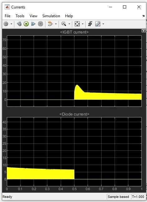
Figure 1.3
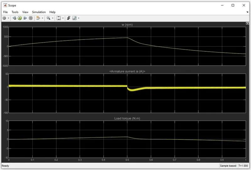
Figure 1.4
Conclusion:-
The decrease in duty cycle will reduce the speed of motor. So, in order to achieve higher RPM and good efficiency of the motor the dutycycle should be always high.
1B) The armature current shoot-up from the scope results:-
From the figure 1.2 & 1.4 it is clear that the decrease in duty cycle will reduce the spike during the starting of DC motor.
For the DC motor the armature current can be given by the following equation.
Ia = (V-Eb)/R
where,
Ia = armature current
V = supply current
Eb= back emf
R = armature Resistance
During the starting of motor the back emf will be zero.
since, Eb = 0
therefore Ia = V/R
The armature resistance value of DC motor will be in the less than 1 Ohm and single phase supply voltage will around 220 to 230 V. hence there will be large armature current during the starting of motor but after the starting the value of Eb start to increase then the value Ia starts to decrease in motor.
1C) The Four-Quadrant Chopper DC Drive (DC7) block and Comparing it with the H-bridge model:-
The Four-Quadrant Chopper DC Drive (DC7) block represents a four-quadrant, DC-supplied, chopper (or DC-DC PWM converter) drive for DC motors. This drive features closed-loop speed control with four-quadrant operation. The speed control loop outputs the reference armature current of the machine. Using a PI current controller, the chopper duty cycle corresponding to the commanded armature current is derived. This duty cycle is then compared with a sawtooth carrier signal to obtain the required PWM signals for the chopper.
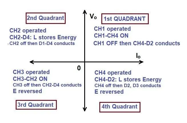
The main advantage of this drive, compared with other DC drives, is that it can operate in all four quadrants (forward motoring, reverse regeneration, reverse motoring, and forward regeneration). In addition, due to the use of high switching frequency DC-DC converters, a lower armature current ripple (compared with thyristor-based DC drives) is obtained. However, four switching devices are required, which increases the complexity of the drive system.
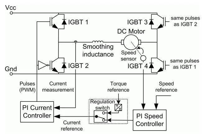
The Four-Quadrant Chopper DC Drive block uses these blocks from the Electric Drives/Fundamental Drive Blocks library:
- Speed Controller (DC)
- Regulation Switch
- Current Controller (DC)
- Chopper
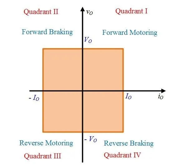
Comparisions of Four-Quadrant Chopper DC Drive (DC7) block with H-bridge Model
|
Four-Quadrant Chopper DC Drive |
BJT H-bridge Model |
|
Four-Quadrant Chopper can operate in all four modes (Forward Motoring, Forward Braking, Reverse Motoring and Reverse Braking). |
H-bridge can operate only in two modes (Forward and Reverse). |
|
Four-Quadrant Chopper Regenerative Braking is possible |
H-bridge Regenerative Braking is not possible. |
|
It provides better efficiency and operates at high power levels. |
Comparatively less efficient and operates at moderate power levels. |
|
It uses PI controller for both speed and current control |
It does not have any PI controller. |
|
PI controller provides the necessary supply power for the field winding of DC motor. |
Separate DC voltage source is required for the excitation of field winding of DC motor. |
2) Developing a 2-quadrant chopper using simulink & explain the working of the same with the relevant results.
Description
The Two-Quadrant Chopper block represents a two-quadrant controlled chopper for converting a fixed DC input to a variable DC output. The block contains two switching devices. Options for the type of switching devices are:
- GTO — Gate turn-off thyristor
- Ideal semiconductor switch
- IGBT — Insulated-gate bipolar transistor.
- MOSFET — N-channel metal-oxide-semiconductor field-effect transistor
- Thyristor
- Averaged Switch.
There are two model variants for the block.
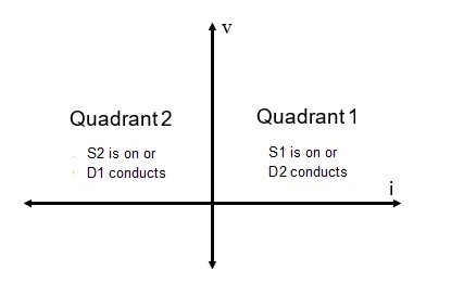
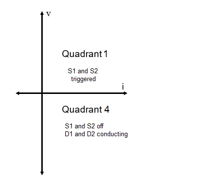
1)First- and second- quadrant chopper. This block choice is the default. The figures show the equivalent circuit and the operation for the first- and second- quadrant model.
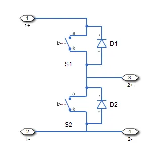
figure 2.1
Graph:-
2)First- and fourth- quadrant chopper. The figures show the equivalent circuit and the operation for the first- and fourth- quadrant model.
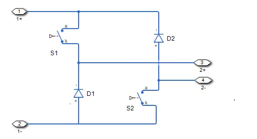
figure 2.2
Graph:-
Two-Quadrant Chopper 200 HP DC Drive: -
Two-quadrant chopper DC drive during speed regulation is shown below.
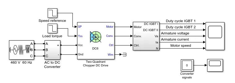
figure 2.3
The 200 HP DC motor is separately excited with a constant 150 V DC field voltage source. The armature voltage is provided by an IGBT buck-boost converter controlled by two PI regulators. The buck-boost converter is fed by a 630 V DC bus obtained by rectification of a 460 V AC 60 Hz voltage source. In order to limit the DC bus voltage during dynamic braking mode, a braking chopper has been added between the diode rectifier and the DC6 block.
The first regulator is a speed regulator, followed by a current regulator. The speed regulator outputs the armature current reference (in p.u.) used by the current controller in order to obtain the electromagnetic torque needed to reach the desired speed. The speed reference change rate follows acceleration and deceleration ramps in order to avoid sudden reference changes that could cause armature over-current and destabilize the system. The current regulator controls the armature current by computing the appropriate duty ratios of the 5 kHz pulses of the two IGBT devices (Pulse Width Modulation). For proper system behaviour, the two IGBT devices have opposite instantaneous pulse values. This generates the average armature voltage needed to obtain the desired armature current. In order to limit the amplitude of the current oscillations, a smoothing inductance is placed in series with the armature circuit.
Simulation
Before starting the simulation, set the initial bus voltage to 630 V via the GUI block ('Initial States Setting' button and 'Cbus' variable).
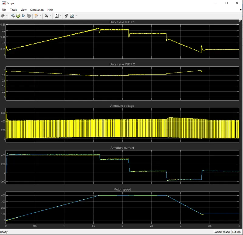
Start the simulation. You can observe the motor armature voltage and current, the two IGBT pulses and the motor speed on the scope. The current and speed references are also shown.
The speed reference is set at 400 rpm at t = 0 s. Initial load torque is 814 N.m.
Observe that the motor speed follows the reference ramp accurately (+250 rpm/s) and reaches steady state around t = 2 s. The armature current follows the current reference very well, with fast response time and small ripples. Notice that the current ripple frequency is 5 kHz.
At t = 2.1 s, the load torque passes from 814 N.m to 100 N.m. The motor speed recovers fast and is back at 400 rpm at t = 2.75 s. The current reference lowers to about 40 A to generate a smaller electromagnetic torque, the load torque being reduced. As observed before, the armature current follows its reference perfectly.
At t = 2.75 s, the speed reference jumps down to 100 rpm. In order for the motor to decelerate following the negative speed ramp, the armature current reverses down to -160 A to generate a braking electromagnetic torque (dynamic braking mode). This causes the DC bus voltage to increase. The braking chopper limits the voltage value.
At t = 3.4 s, the motor speed reaches 100 rpm and the current reverses back to 40 A.
At t = 4 s, the speed stabilizes around its reference.
Result:-
3) Operation of BLDC motor:-
The Motor operation is based on the attraction or repulsion between magnetic poles.Using the three-phase motor shown in Figure 3.1 the process starts when current flows through one of the three stator windings and generates a magnetic pole that attracts the closest permanent magnet of the opposite pole. The rotor will move if the current shifts to an adjacent winding. Sequentially charging each winding will cause the rotor to follow in a rotating field. The torque in this example depends on the current amplitude and the number of turns on the stator windings, the strength and the size of the permanent magnets, the air gap between the rotor and the windings, and the length of the rotating arm.
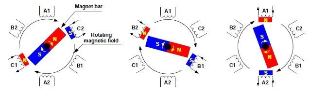
Figure 3.1
BRUSHLESS DC MOTOR CONTROL:-
- Switch Configuration and PWM
Brushless DC motors uses electric switches to realize current commutation, and thus continuously rotate the motor. These electric switches are usually connected in an H-bridge structure for a single-phase BLDC motor, and a three-phase bridge structure for a three-phase BLDC motor shown in Figure 3.2 Usually the high-side switches are controlled using pulse-width modulation (PWM), which converts a DC voltage into a modulated voltage, which easily and efficiently limits the startup current, control speed and torque. Generally, raising the switching frequency increases PWM losses, though lowering the switching frequency limits the system’s bandwidth and can raise the ripple current pulses to the points where they become destructive or shut down the BLDC motor driver.
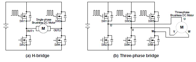
figure 3.2
- single-phase BLDC driver
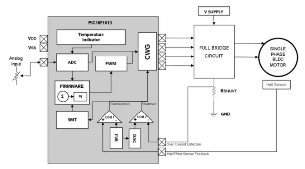
figure 3.3
The single-phase driver based on Microchip’s PIC16F1613 8-bit microcontroller, chosen because of its low pin count and on-chip peripherals that can control the driver switches, measure the motor speed, predict the rotor position and implement fault detection. This application uses the following peripherals: complementary waveform generator (CWG), signal measurement timer (SMT), analog-to-digital converter (ADC), digital-to-analog converter (DAC), capture compare PWM (CCP), fixed voltage reference (FVR): timer, comparator, and temperature indicator. These peripherals are internally connected by firmware, which reduces the number of external pins required.
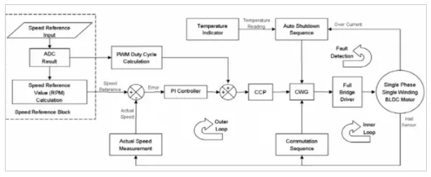
figure 3.4
Control diagram of motor driver
The full-bridge circuit, which energizes the motor winding, is controlled by the CWG output. A Hall sensor is used to determine the rotor position. Current that passes through the motor winding is translated into a voltage through the sense resistor Rshunt for over-current protection. The speed can be referenced in an external analog input. Figure 3.4 shows the control diagram of the motor driver; for this application, the rated motor voltage is 5V and rated speed 2400r/min. The motor driver supply voltage is 9V. The speed reference can be any analog input. The microcontroller’s ADC module has 10-bit resolution and up to eight channels, making it suitable for different kinds of analog input. This is being used to derive the speed reference and the initial PWM duty cycle, used to initialize the speed of the motor based on the source of the speed reference.
The initial duty cycle can be increased or reduced by the result of the proportional-integral (PI) controller and the new duty cycle value loaded in the CCP, the PWM output of which is used as the initial source of the CWG to control the modulation of the lower side switches of the full-bridge driver and, hence, the speed of the motor.