Week 10 - Simulating Combustion of Natural Gas.
Simulating Combustion of Natural Gas
Aim:
Part I
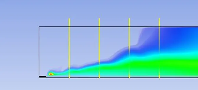
Perform a combustion simulation on the combustor model and plot the variation of the mass fraction of the different species in the simulation using line probes at different locations of the combustor as shown in Fig. You need to plot for CO2, H2O, CH4, N2, O2, NOx emissions & Soot formation.
Part II
As you must have observed from the above simulation, the NOx and soot are getting formed at the outlet of the combustor. Such formation has harmful effects on the environment and humans. The stringent government norms also demand the least formation of NOx and soot and to satisfy those requirements, you need to check the effect of adding the water in the fuel.
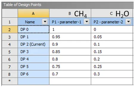
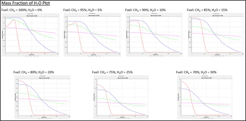
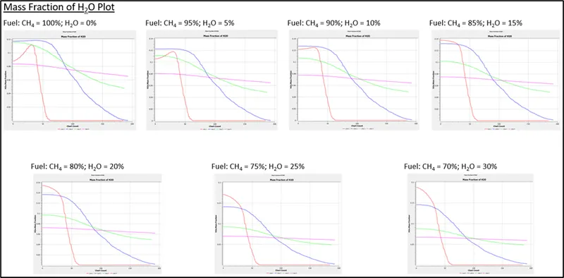
In this part, you need to add the water content in the fuel from 5% to 30% by mole and observe the effect of it on the results. It is necessary to provide line plots and contours to prove your claim.
You can use the parametric study approach if required.
Note: -
- Use methane-air-2step as a mixture material than methane-air. [It allows to add water in the fuel or air]
- Use a one-step soot model to calculate the soot formation.
Theory:
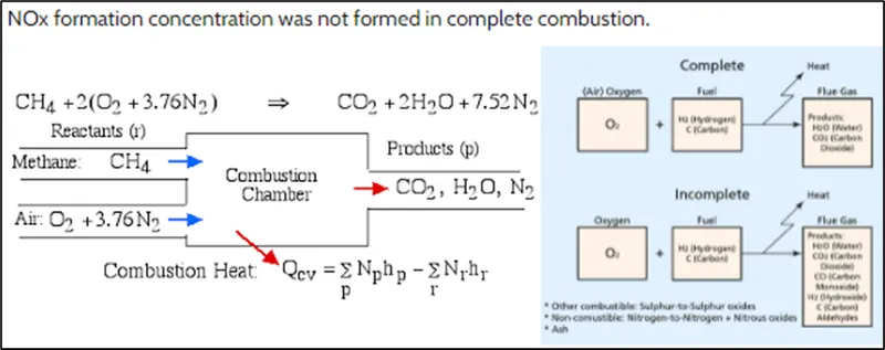
The combustion is defined as a chemical reaction in which a hydrocarbon fuel reacts with an oxidant to form products, accompanied with the release of energy in the form of heat. Being an integral part of various engineering applications like internal combustion engines, furnace, power station combustors, combustion exhibits itself as a wide domain during the design, analysis, and performance characteristics stages of the above-mentioned applications. To solve the complex equations from chemical kinetics and to yield information about the reaction mechanism proper physical modeling must be done. In this project, the combustion process is simulated with the help of CFD software ANSYS Fluent. When the combustion is incomplete, various pollutants are formed, some pollutants are carbon dioxide, carbon monoxide, lead, nitric oxide. In this project, the formation of pollutants from NOX emission which mainly consists of NO, NO2, N2O and soot formation which is a mass of impure carbon particles is simulated and the variation of mass fraction of pollutants from NOX emission and soot formation with the addition of water into the fuel in studied.
Simulation Procedure:
- Import the given model in to SpaceClaim.
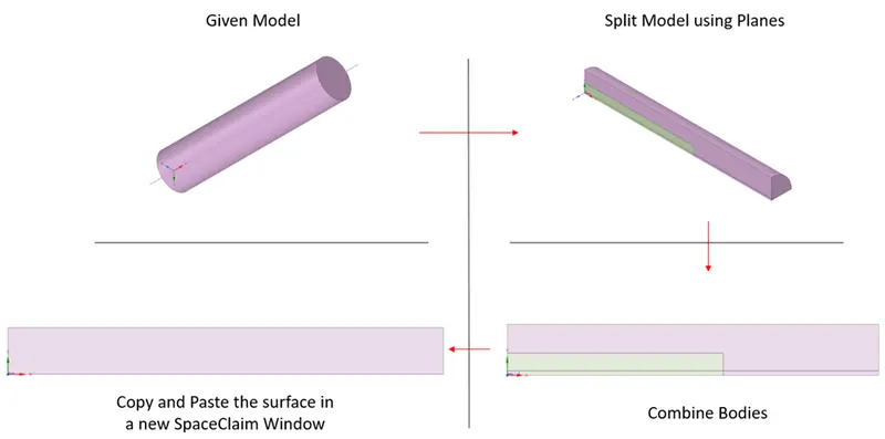
- For the simulation we can simplify the given model to a 2D surface. Convert the model to a 2D surface as shown below.
- Open Mesh module. Keep element size to 1mm. Methods = Triangles. Capture proximity = Yes.
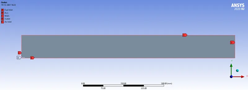
- Set Boundary Names (Named References) as shown in the image below:
- Open Fluent.
- Solver Type = Pressure based.
- Solver Time = Steady State
- Velocity Formulation = Absolute
- 2D Space = Axisymmetric (X-Axis)
- Switch on Energy in Models Tab.
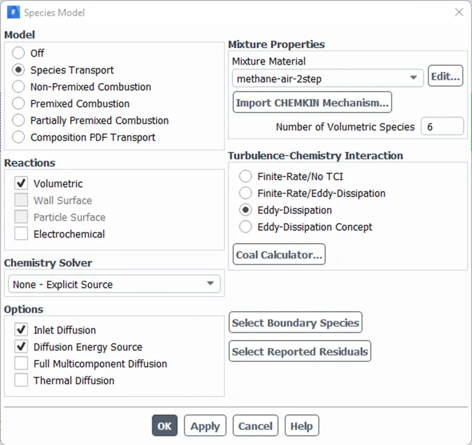
- Go to Species window in Models Tab. Set it as shown below:
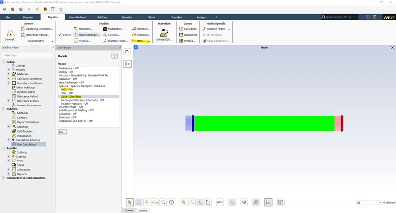
- Switch On NOx and Soot Models as shown below:
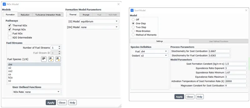
- Boundary Conditions:
- Air Inlet velocity = 0.5m/s. Temperature = 300K. Species Mass Fraction of O2 = 0.23.
- Fuel Inlet Velocity = 80m/s. Temperature = 300K. Species Mass Fraction of CH4 = 1. [Case 1]
- Fuel Inlet Velocity = 80m/s. Temperature = 300K. Species Mass Fraction of CH4 and H2O = Parametric. [Case 2]
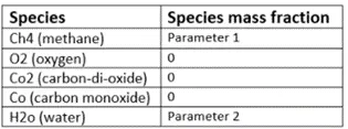
- Pressure Outlet.
- Walls as default.
- Hybrid Initialization.
- Solution Tab --> Definitions (Report) --> New --> Surface Report --> Area weighted avg. Set field variables to Mass Fraction of NOx and Carbon Soot, respectively, at the outlet. Set as Output Parameter for both, Mass Fraction of NOx and Mass Fraction of Carbon Soot in Case 2.
- Also create a contour and animation of the contour for Static Temperature across the whole system.
- No. of Iterations = 1500.
- Calculate.
- Open CFD Post. Create 4 lines at 0.1m, 0.3m, 0.5m and 0.7m from the inlet for post processing results.
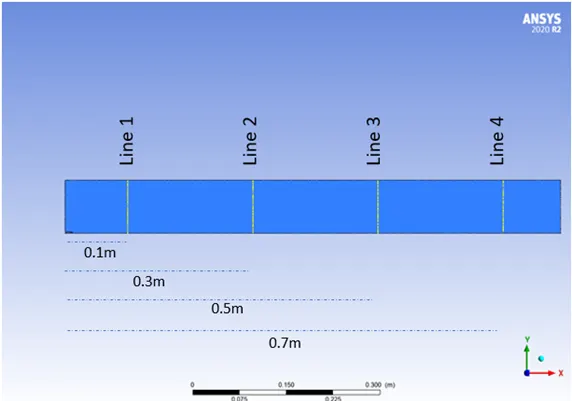
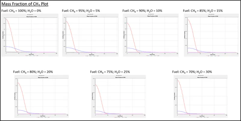
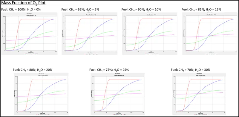
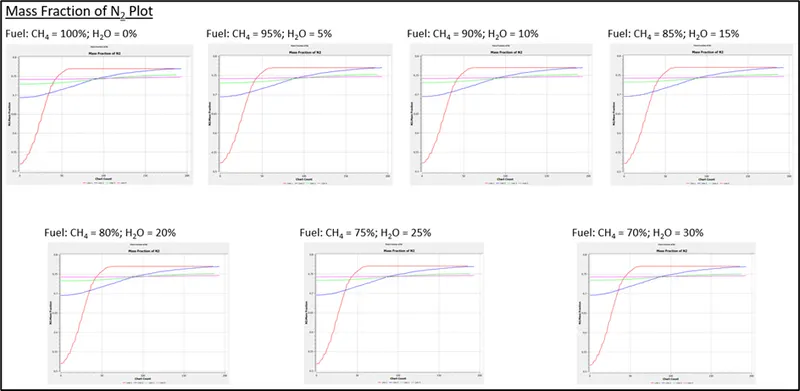
- Create Mass Fraction Plots for CH4, O2, H2O, N2, CO2, CO, NOx, and Carbon Soot.
- Exit CFD Post.
- Open Parameter Set. Set the following Design points for % of CH4 and H2O in fuel mixture.
Results:
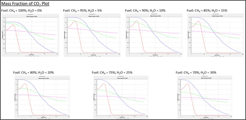
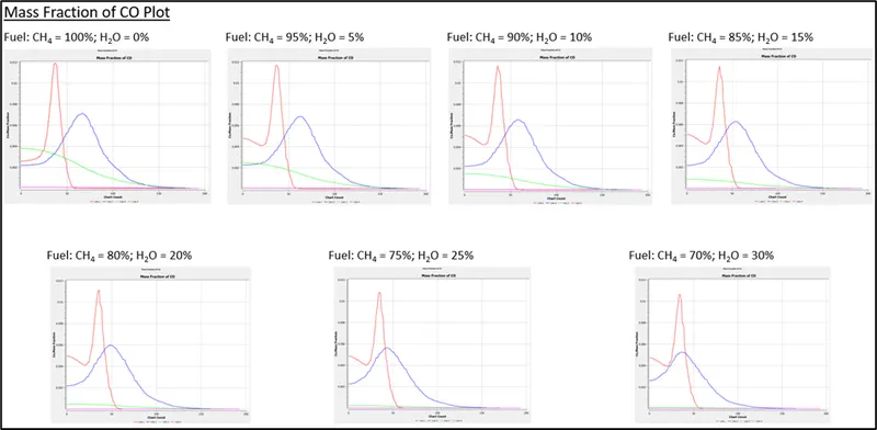
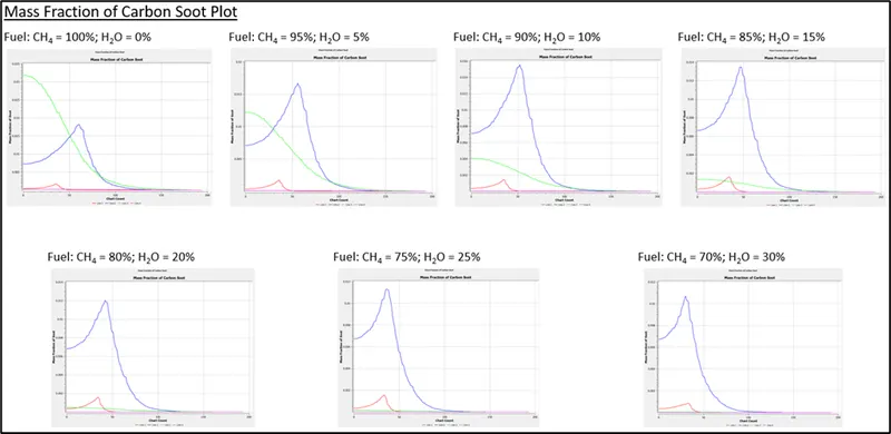
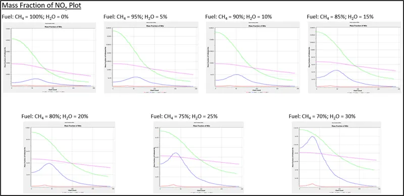
Conclusion:
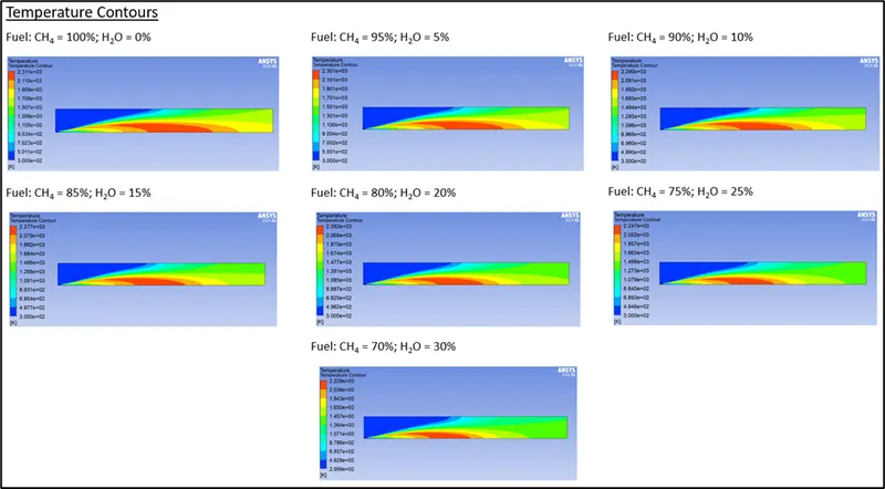
- The temperature decreases from 2311K to 2229K as we increase water % in fuel from 0% to 30%.
- The mass fraction of CO increases as water content in fuel increases, indicating incomplete combustion.
- N2 and O2 plots show that they have no dependency over the water content in fuel.
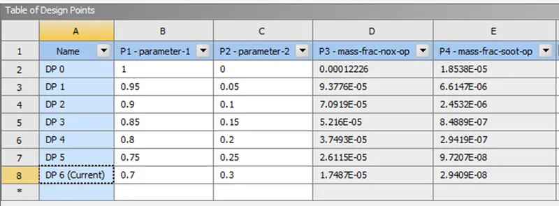
- The mass fraction of pollutants such as NOx and Carbon soot (as shown in the table below) decreases as water content in fuel increases.