Week 10 - Challenge 3 - Door Trim Lower with Engineering Features
DOOR TRIM LOWER WITH ENGINEERING FEATURES - HEAT STAKES AND LOCATORS
In this project, a door trim lower plastic component is created using the given Class A surface. On the surface created, Heat Stakes and Locators were added by considering the design requirements and draft analysis is conducted on the model.
Thermal Staking
Thermal staking is an assembly method that uses controlled melting and reforming of a plastic stud or boss to capture or lock another plastic material or metal component of an assembly in place. The plastic stud protrudes through a hole in the component to be locked in place.
Steps in heat staking:
- A plastic part with a protruding stud or boss is placed over a hole in another part, which can be plastic, metal or other material.
- A heated tip contacts the top of the stud, which melts and fills the volume of tip cavity to produce a head, locking the other part in place.
- The progressive melting of plastic under continuous pressure forms the head.
- The tip is removed and the plastic cools down and re-solidifies, resulting in a strong and permanent bond.
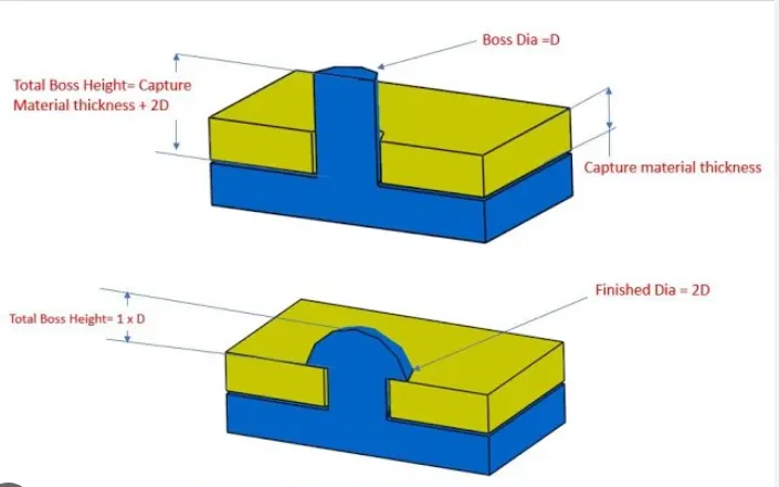
Fig 1. Heat Staking.
Design of door trim lower
The given Class A surface is checked for gaps or irregularities using boundary or join command. Here no such issues were present.
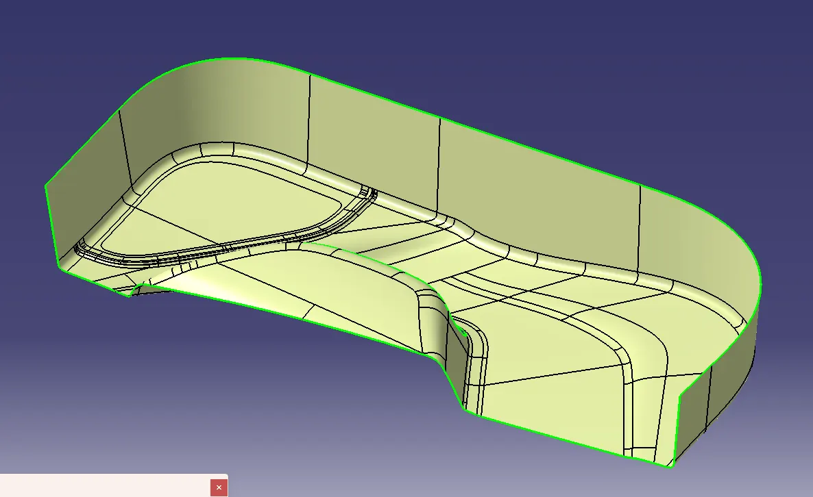
Fig 2. Class A surface.
Tooling Axis creation
- The class A surface is examined and found that almost all the faces can be cleared if tooling is given along Y direction.
- Bisecting method is adopted for the creation of tooling axis.
- An extract of the flat surface is taken and a point is created on the extract.
- An axis system is created at the point
- An intersect is taken between XY plane and the class A surface.
- Two lines are constructed tangent to the side walls and a bisecting line is taken as the tooling axis (temporarily).
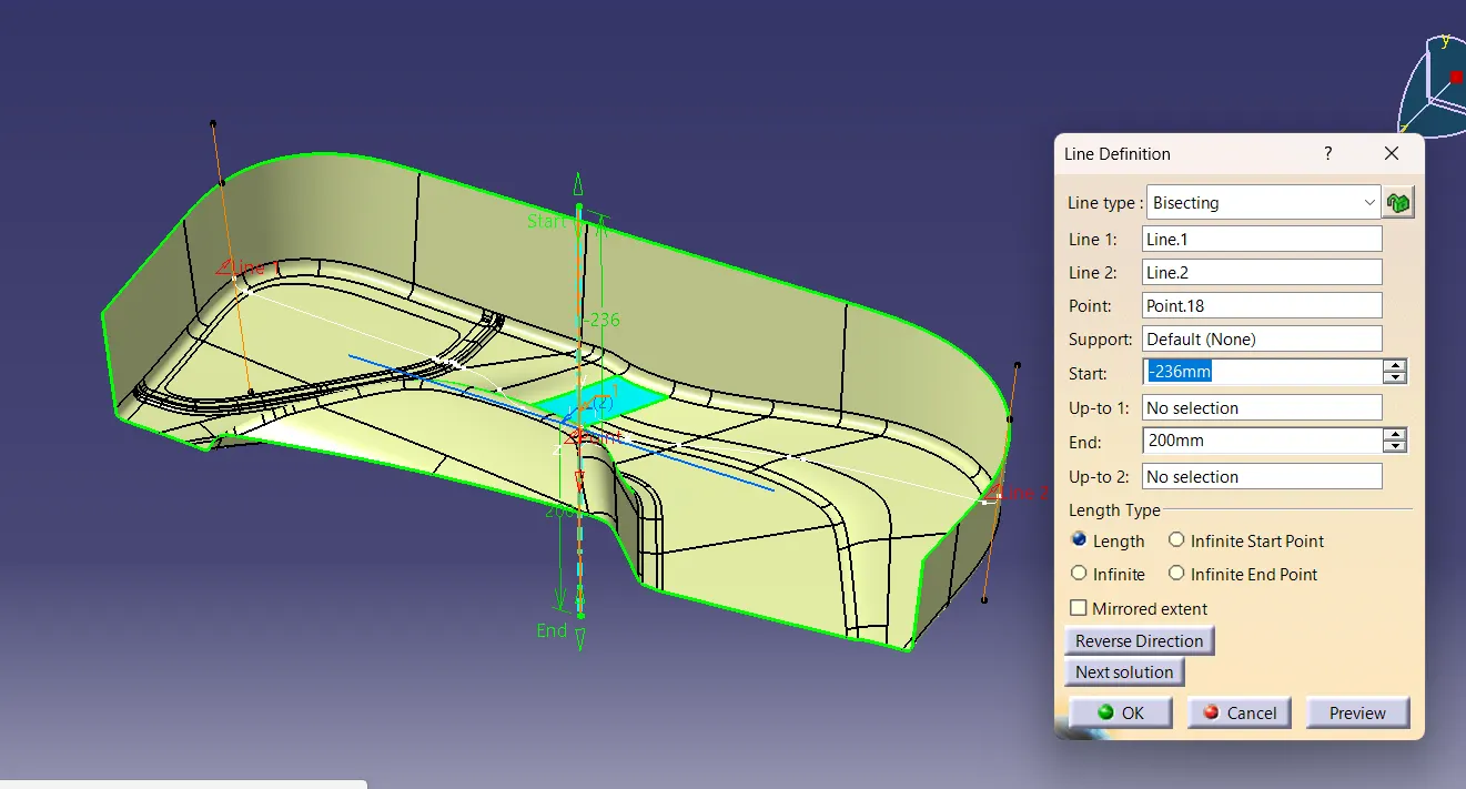
Fig 3. Tooling Axis creation.
Draft Analysis on Class A
Draft analysis is conducted on the class A surface to determine whether the surface clears the 3° draft using the considered tooling axis.
Steps:
- In the material view mode, select customize view parameters and select material option.
- Select the Feature draft analysis command.
- Select the compass icon, drag the compass and place i along the tooling axis.
- Select the Class A surface and check whether it clears the draft.
- Here the surface clears the draft and the tooling axis taken is correct.
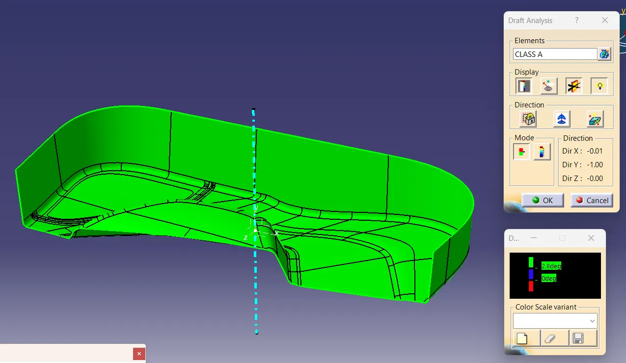
Fig 4. Draft analysis on Class A surface.
Class B surface creation
Since the surface is a complex one, the class A surface is offseted by 2.5mm inwards to create class B surface. But few patches were missing in the newly offseted surface.
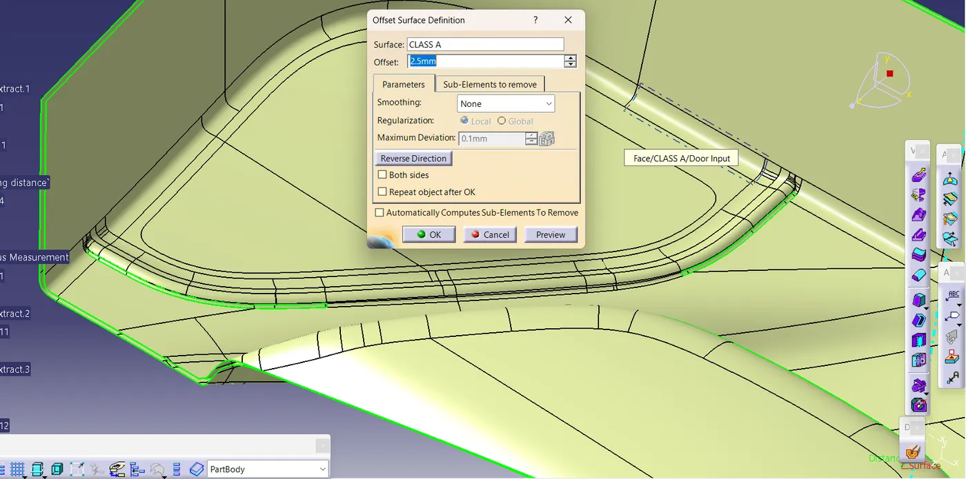
Fig 5. Offseted surface with missing patches.
The missing portions were cleared using multiple extract, boundary, join, extrapolate, multi section surface and trim commands and fillets were also given in the missing regions.
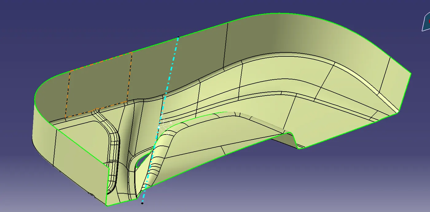
Fig 6. Class B surface after corrections.
Creation of Class C surface
Sweep command is used to create Class C surface from the boundary of Class A surface. The draft angle with respect to the tooling axis is taken as 3° for faces perpendicular to the tooling axis. For faces that are parallel to the tooling axis, sweep angle is taken as 90° with respect to the surface.
The boundary of Class A is not taken in a single stretch since the generation of C surface does not occur correctly. It is taken as multiple boundaries, providing different limits and sweep operation is done separately for those regions. At some regions where we need to connect these individual sweep surfaces, we use spline, boundary and multi section surface commands.
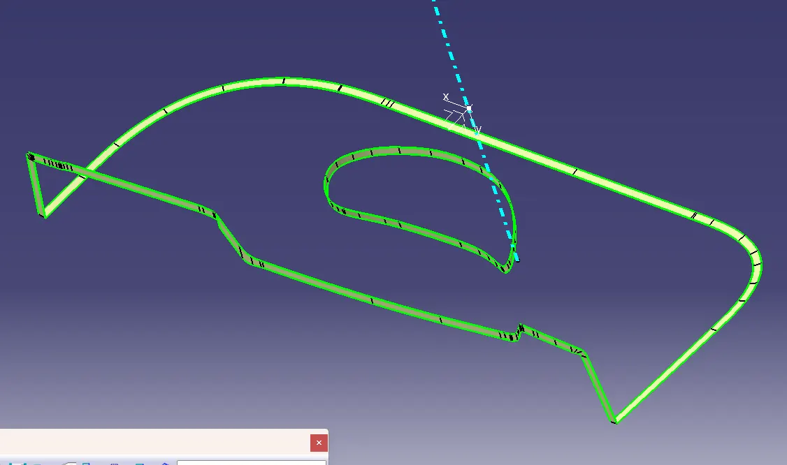
Fig 7. Class C surface.
Final Trim
First Class A is joined with the Class C surface after extrapolation of the surfaces. The new surface is trimmed with Class B to create the final trim surface of the part.
Fig 8. Class A joined with Class C.
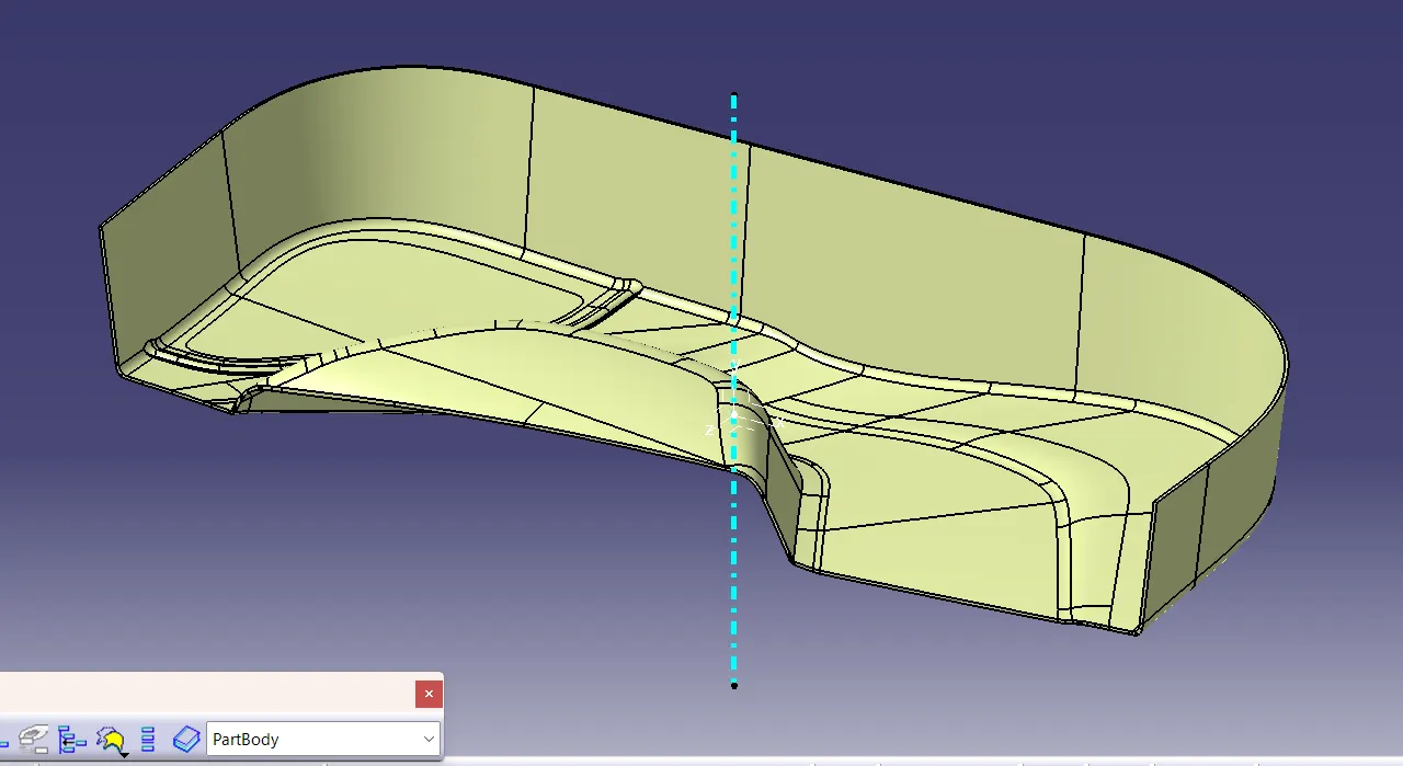
Fig 9. Final Trim.
The surface part is created into a closed body using Close Surface command in part workbench.
The solid part is merged to the main part body using assemble boolean operation.
Creation of Locators
The 3-2-1 principle is adopted for the part to part fixation in automotive industry. According to the 3-2-1 principle, a workpiece has 12 degrees of freedom.
- Translational movement along X axis.
- Translational movement along Y axis.
- Translational movement along Z axis.
- Rotational movement along X axis.
- Rotational movement along Y axis.
- Rotational movement along Z axis.
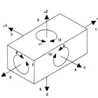
Fig 10. Twelve degrees of freedom.
To fix two components together, at least 11 degrees of freedom must be arrested. The remaining one degree is the fixing direction. In order to achieve this arresting, we create 4 way locators. The height of the locators should be greater than that of heat stakes.
Designing locators:
- Sketch for the locator is done.
- Padding is done for a height of 22mm.
- Draft of 0.5° is given with the tooling axis as the pulling direction.
- Fillet of 0.25mm is given for the edges.
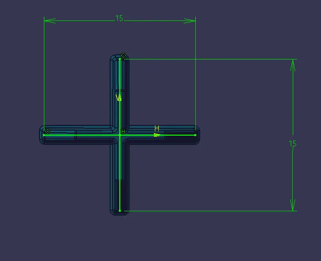
Fig 11. Sketch for 4 way locator.
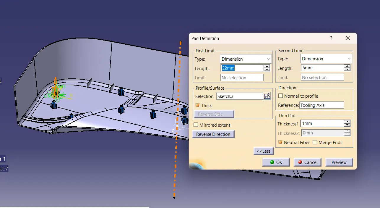
Fig 12. Padding for locator.
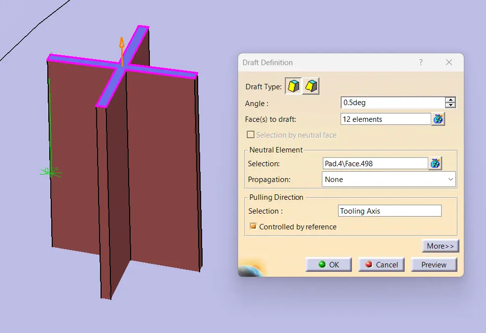
Fig 13. Draft for locator.
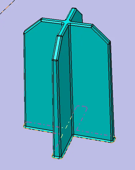
Fig 14. Four way locator.
The locator is placed on 2 locations in the door trim design. For that, the locator is copied and translated to the next point after giving paste special. The two locators are merged with the main part using the Union Trim boolean operation.
Creation of heat stakes
Heat stakes are created at the points already given in the question by considering the requirements for heat stake design.
- Sketch for the heat stake is created at a point which was already given.
- Pad operation is done on the sketch for a height of 18mm.
- The thickness of the stakes is given as 1.5mm.
- Drafting of 0.5° is given for both outer surface and inner surface with the tooling axis as the pulling direction.
- Edge fillets of 0.25mm were given.
- Supporting ribs are given for the heat stakes.
- Sketching for the ribs was done.
- 1mm thickness was given for the support ribs.
- Pad operation was done on the sketch for a height of 9mm, which is half of the heat stake height.
- Draft of 0.5° was given with the tooling axis as the pulling diretion.
- Fillets of 0.25mm were given for the edges.
- The rib body is attached to the heat stake using the boolean operation union trim.
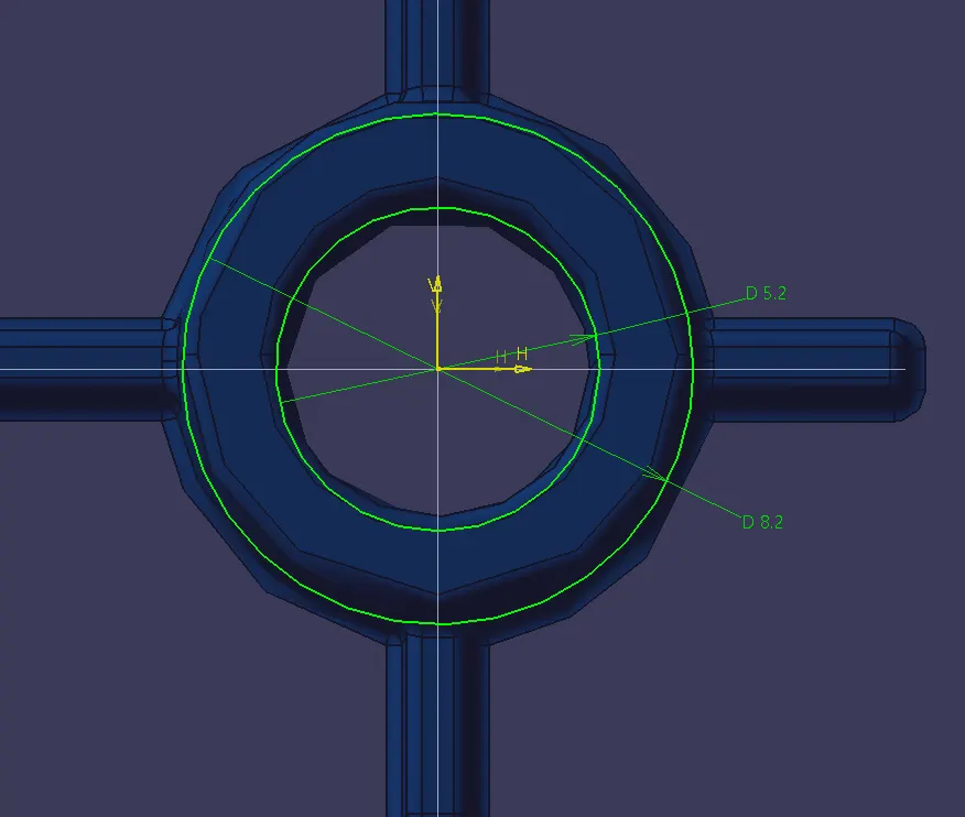
Fig 15. Sketch for heat stake.
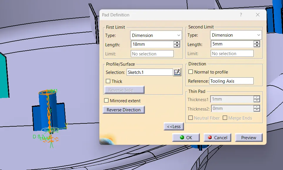
Fig 16. Pad operation for heat stake.
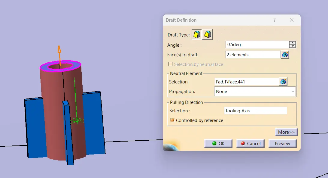
Fig 17. Draft for heat stake.
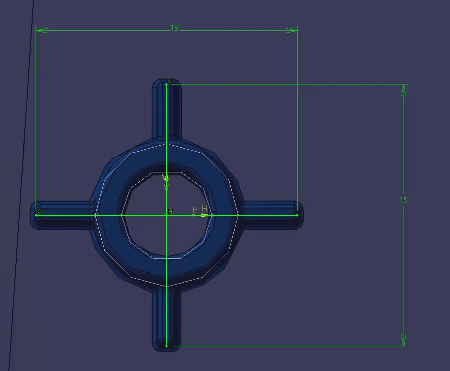
Fig 18. Sketch for supporting ribs.
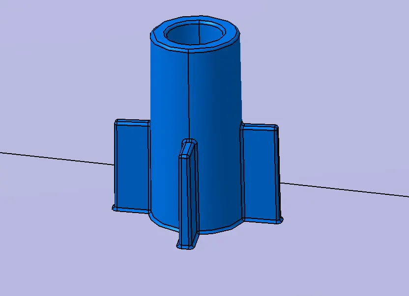
Fig 19. Heat stake with supporting ribs.
The heat stake now created (along with supporting ribs) should be replicated at all the given positions.
- The heat stake design is copied and pasted using paste special at all the given points using point to point transformation.
- Then all the heat stakes are attached to the main body using boolean operation union trim.
Ribs are also added as supports in the design by following the design requirements for the ribs.
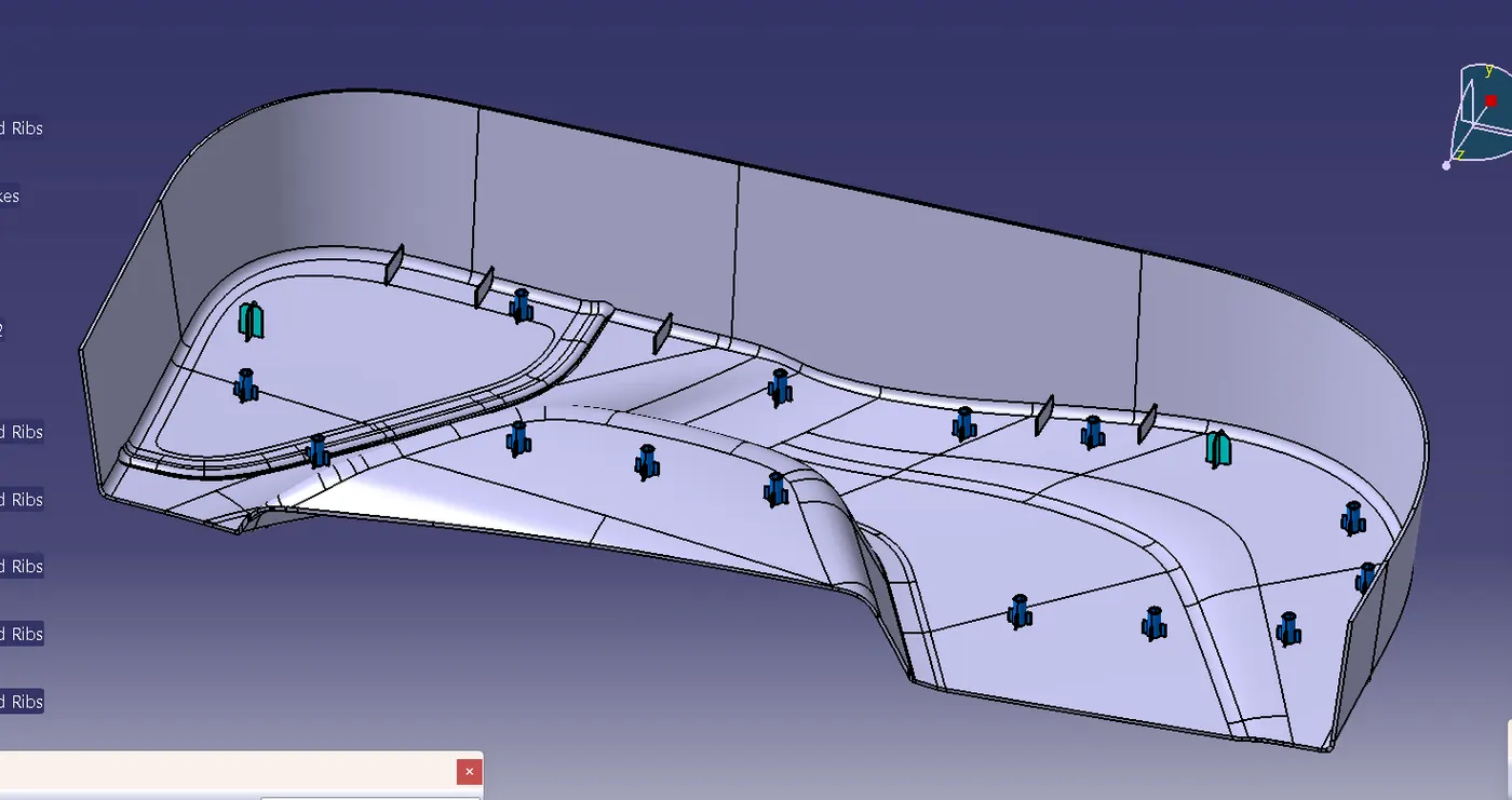
Fig 20. Final design with heat stakes and locators on the door trim lower part.
Draft analysis on final design
Feature draft analysis is conducted on the final part to check whether the heat stakes and locators clear the draft.
Steps:
- In the material view mode, select customize view parameters and select material option.
- Select the Feature draft analysis command.
- Select the compass icon, drag the compass and place it along the tooling axis.
- Select the part by clicking anywhere on it and check whether it clears the draft.
- Here the B side features ie, the heat stakes, locators and ribs cleared the draft.
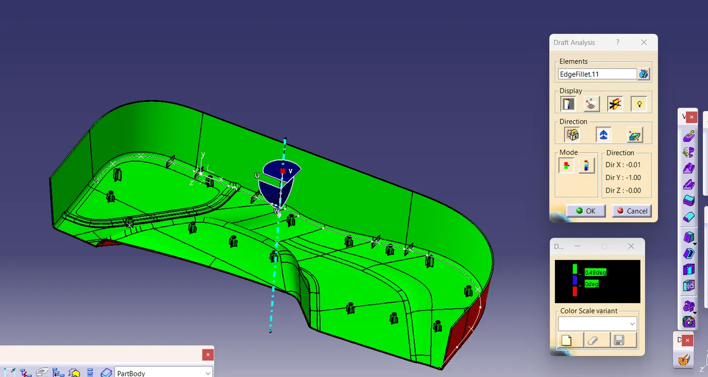
Fig 21. Final draft analysis.
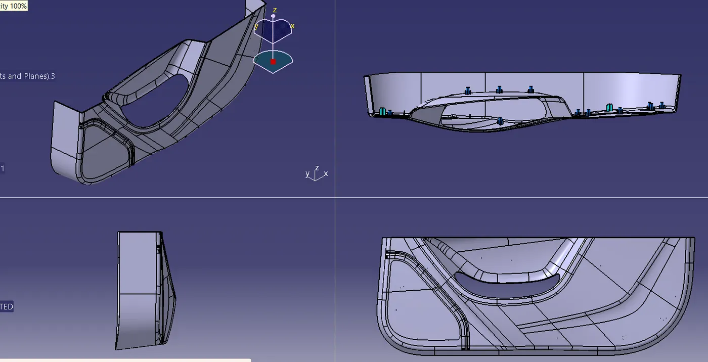
Fig 22. Multiple views of the final design.
Thank You.