Week 11 - Project - A pillar Design with Master Section
A PILLAR DESIGN WITH MASTER SECTION
In this project, an A pillar plastic body is created using the given Class A surface. A dog house is also created on the body using the given Master Section, following the design requirements and rules and draft analysis is conducted on the body.
Master Section
In automotive design, a master section is a parameterized model of a vehicle body that guides the NPD (New Product Design) team. It is a guide for design requirements that decide component packaging after technical surfaces. In simple words, master section helps to decide the feasibility, the clearance, the packaging and fixation strategy of a component before integrating on a body of the car.
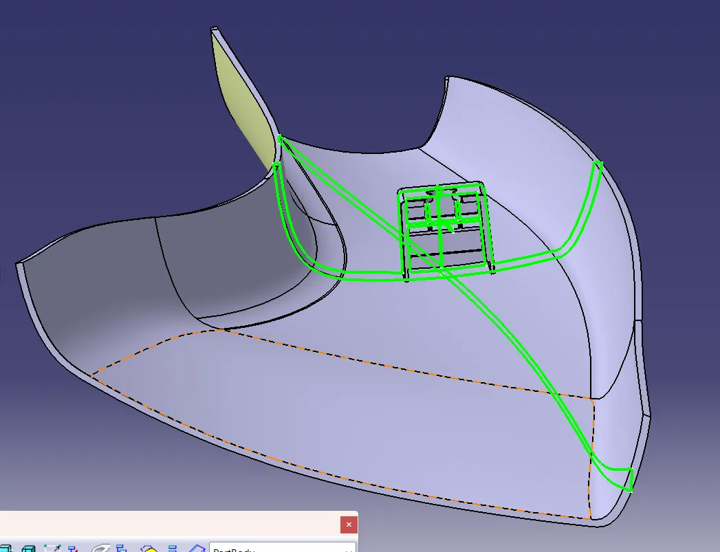
Fig 1. Given master section.
A Pillar
A car is like a building supported by roofs, pillars and a floor. A car stands on six pillars or columns. Some cars got D pillar also. All three pillars can be identified separately if we look from the side of the vehicle. The A pillar is the forward most pillar on a vehicle, supporting its roof at both side ends of the windshield.
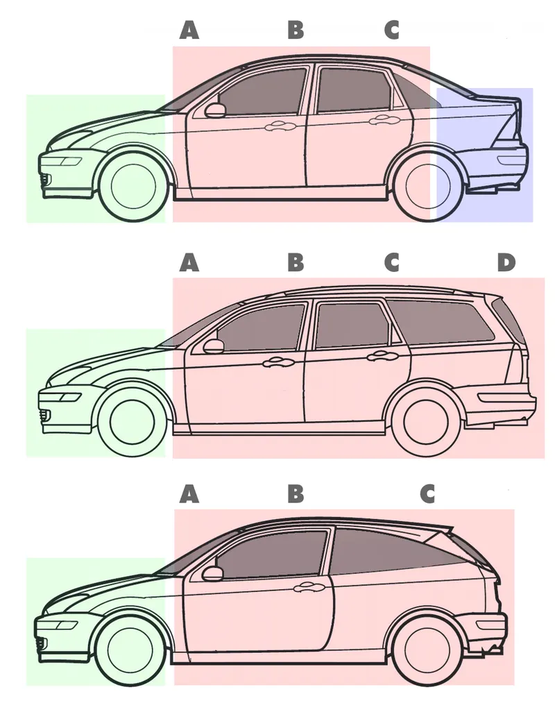
Fig 2. Typical pillar configurations.
A pillar also holds the hinges of the front door. They are generally made of steel alloys. Proper design of the A pillar is also crucial for the safety aspects of the car. They carry a significant amount of load during frontal collision or during rollover of the car. Though increasing the thickness of the A pillar provides more strength, increasing thickness beyond a limit can also affect the visibility of the driver and could cause accidents. So the design of the A pillar should consider both the factors and an optimum design should be adopted giving equal importance to strength and driver's visibility.
DESIGN OF A PILLAR
The given class A surface is checked for gaps and irregularities using boundary or join command. Here no such irregularities were present.
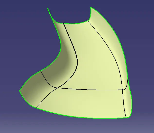
Fig 3. Class A surface.
Creation of tooling axis
- Bisecting method is adopted for the creation of tooling axis.
- Two lines are extracted from the sides of the master section and their bisecting line is taken as the main tooling axis.
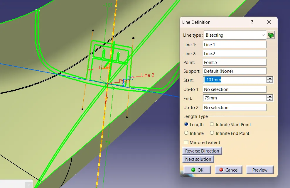
Fig 4. Creation of main tooling axis from master section.
Draft analysis on Class A surface
- In the material view mode, select customize view parameters and select material option.
- Select the feature draft analysis command.
- Select the compass icon.
- Drag the compass and place it along the tooling axis and press lock symbol.
- Select the Class A surface and check whether it clears the draft.
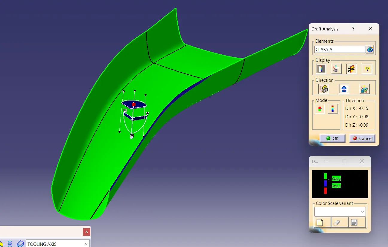
Fig 5. Draft analysis of Class A.
Here, in the Class A surface majority of the part clears the draft whereas a small portion appeared blue in color. Upon checking with the cursor, it was found that the blue regions have got a draft greater than 2.5°. So the surface is okay. However, such issues should be reported to the Class A team and they are supposed to make modifications if required.
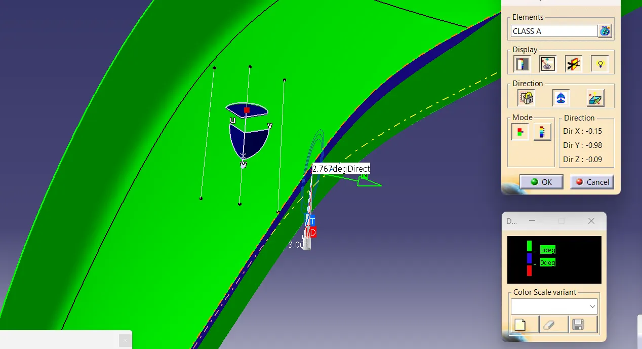
Fig 6. Checking the draft at the blue colored regions.
Creation of Class B surface
For creating the class B surface, the class A surface is offseted by 2.5mm inwards. But the whole surface did not offset properly. A portion was missing on the offseted surface.
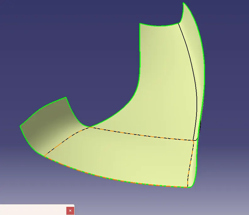
Fig 7. Offseted surface with a missing portion.
The missing portion is rectified using sweep command. In the sweep command the subtype 'with reference surface' in the explicit profile type is selected.
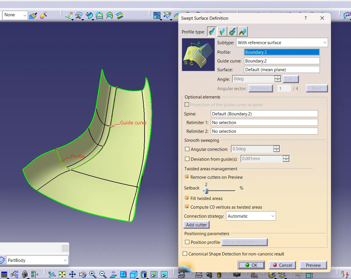
Fig 8. Sweep operation for Class B.
The new surface is joined with the offseted surface using join command and Class B surface is created.
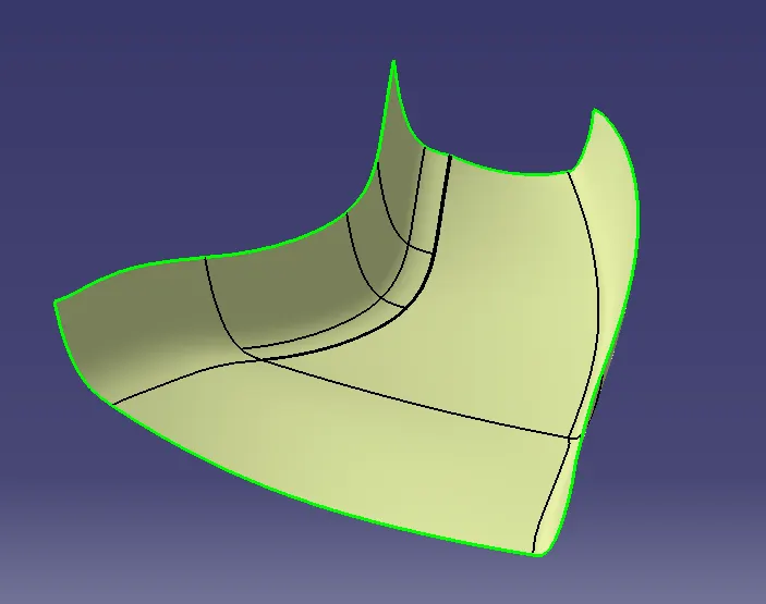
Fig 9. Class B surface.
Creation of Class C surface
For creating the class C surface, the boundaries of the Class A surface are extracted and curve smooth operation is done on the extracted boundaries. Then surfaces are created from these curves using sweep command. The subtype 'with draft direction' is used for faces that are perpendicular to the tooling axis and were given a draft angle of 3°. For faces that are parallel to the tooling axis, the subtype 'with reference surface' is given. Then the newly created surfaces are extrapolated and trimmed with each other and Class C surface is created.
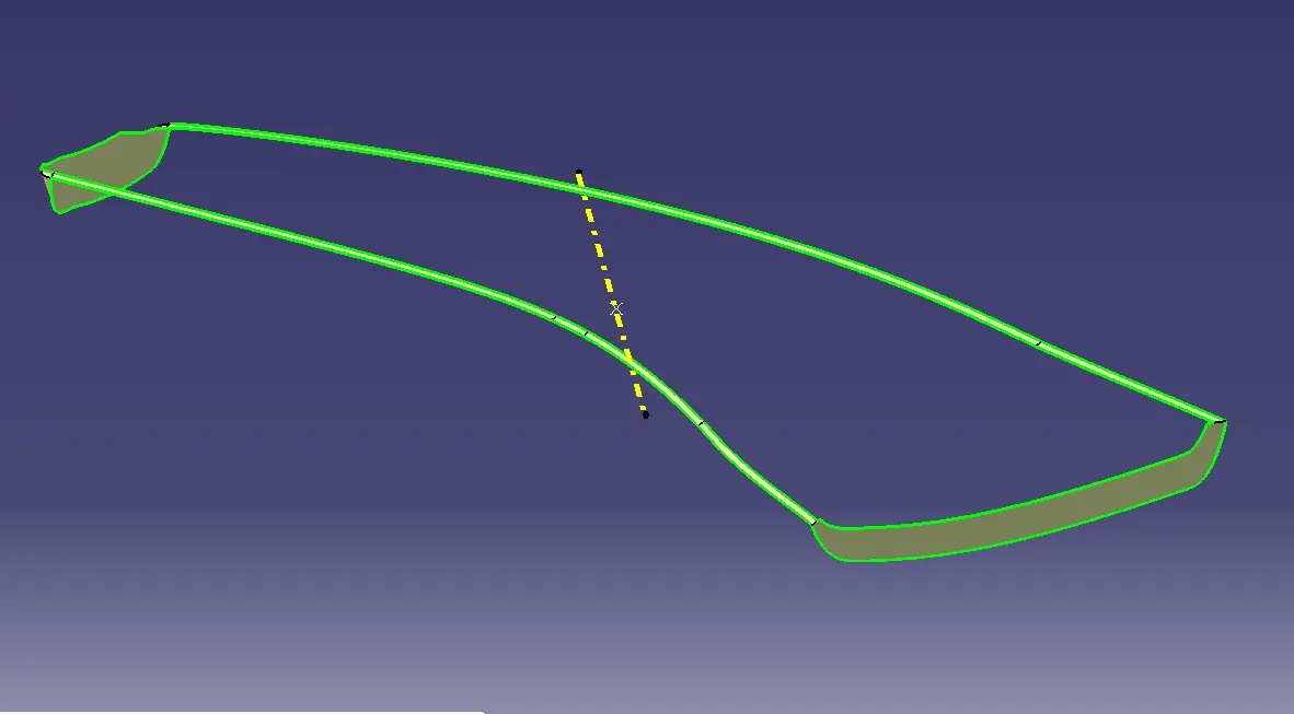
Fig 10. Class C surface.
The C surface is created are joined with class A using join command.
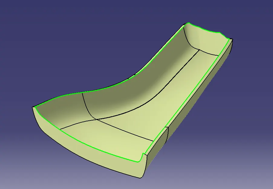
Fig 11. Class A and Class C join.
Final Trim
For the final trim, the Class B surface is extrapolated at the boundaries to merge with the joined surface of A and C. After extrapolation, the Class B surface is trimmed with Class A&C join to create the final trimmed surface.
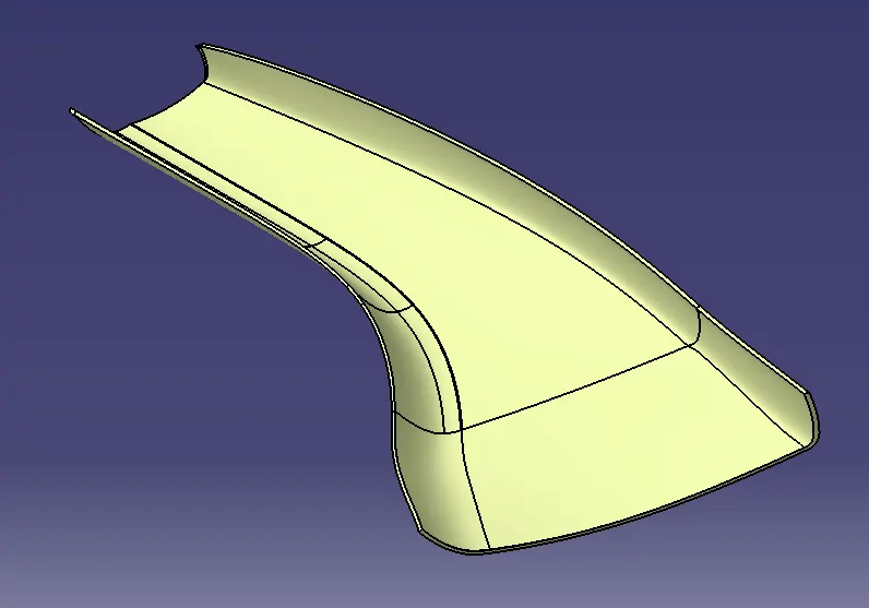
Fig 12. Final trim surface.
The surface part is created into a closed body using Close Surface command in part workbench. The solid part is merged to the main part body using assemble boolean operation.
Draft analysis on the Closed body
A feature draft analysis is conducted on the closed body by following the same steps mentioned in the draft analysis of Class A surface. The part clears the draft according to the analysis.
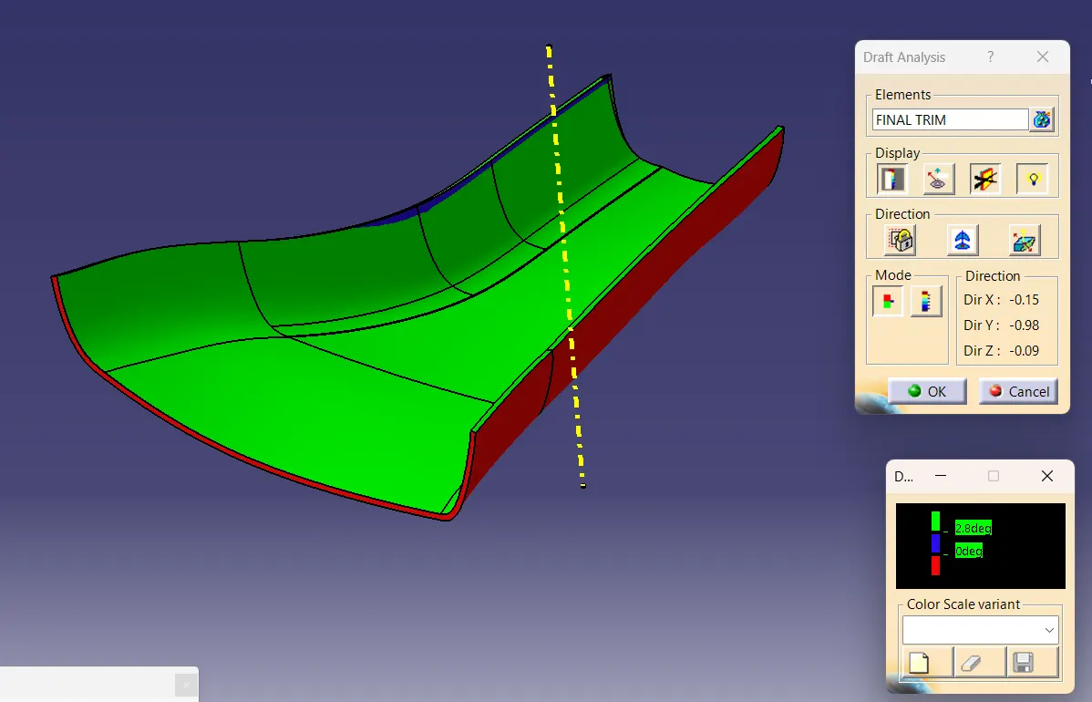
Fig 13. Draft analysis on Closed body.
As seen in the draft analysis of Class A, here also, a small portion appears blue in colour. But, just like the Class A these areas also have got a draft angle which is greater than 2.5°. So the part is okay.
CREATION OF DOG HOUSE USING MASTER SECTION
A plane is created along 3 points of the master section and a sketch is created on that plane. The outer lines of the dog house is sketched making the lines tangent to the master section and the sketch was extruded. The extuding was done on both sides till the ends of the master section facing sideways.
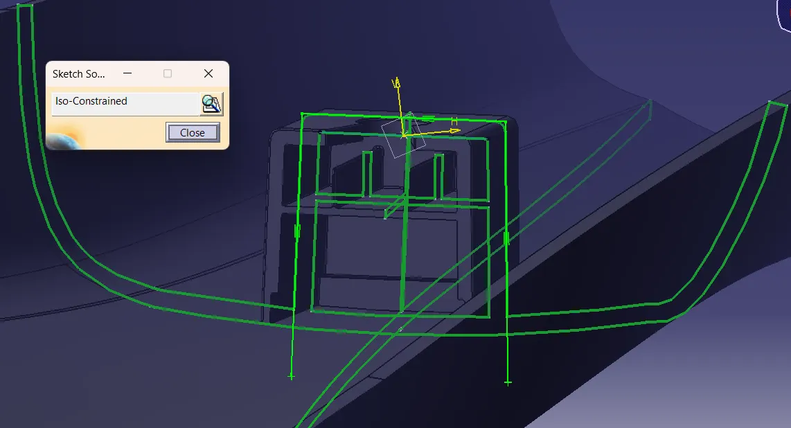
Fig 14. Sketch for the outer surface of dog house with the sketch solving status.
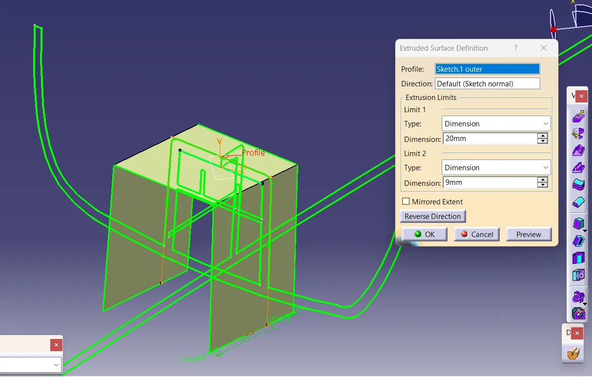
Fig 15. Extruding of the outer surface of dog house.
The rear wall of the dog house was created using multi section surface command and then it is joined with the extruded surface.
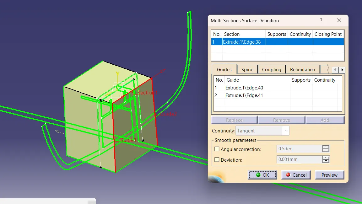
Fig 16. Creation of rear wall of the dog house.
Creation of Side Core Axis
A side core axis is created for clearing the inner faces of the dog house. The rear wall of the dog house is extracted and a line is constructed normal to the surface and it is taken as the side core axis.
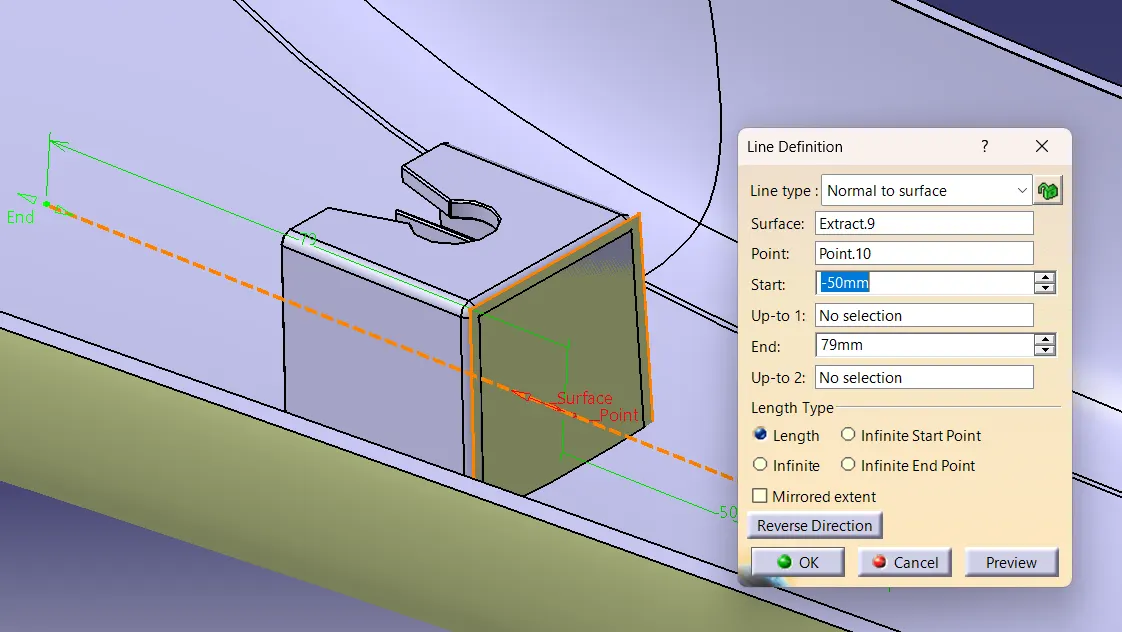
Fig 17. Side core axis creation.
Then the surface of dog house is thickened by 2.5mm using thick surface command and draft of 0.5° is given to the inner surface of the dog house with the side core axis as the pulling direction. No draft is provided for the outer surface since the outer sketch is tangential to the master section.
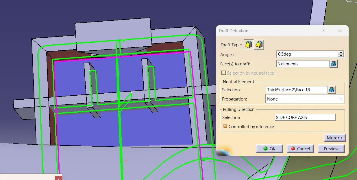
Fig 18. Draft for inner surface.
The inner walls of the dog house is created by creating sketches tangent to the master section, extruding them and then thickening using thick surface command. The horizontal inner wall is thickened by 1.5mm and two vertical walls are thickened by 1mm.
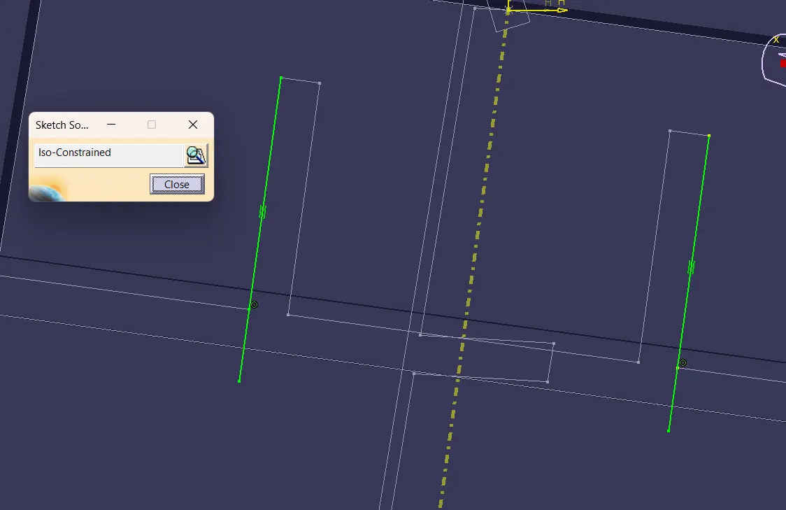
Fig 19. Sketch for inner walls of dog house with sketch solving status.
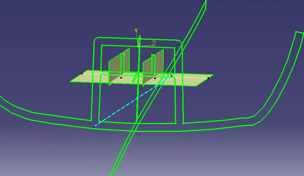
Fig 20. Extruding of inner walls of dog house.
Draft of 0.5° is given to the inner walls also, with the side core axis as the pulling direction.
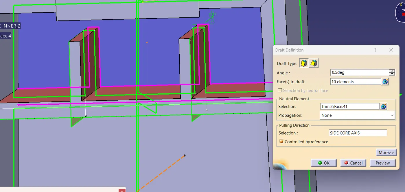
Fig 21. Draft given for the inner walls.
In order to avoid sink marks on the A pillar surface, the thickness of wall at the bottom of the dog house is reduced to almost 40% of the main wall thickness. For creating that portion, the following steps are adopted.
- The inner walls of the dog house is offseted by 0.4xthickness ie, 0.4x2.5=1mm.
- The bottom face of the inner wall, which created second is offseted downwards by 11mm, to give a height of 4mm to the cut portion.
- Then both the offsets are extrapolated and trimmed.
- Then the trim surface is split with the dog house body using split command in the part workbench.
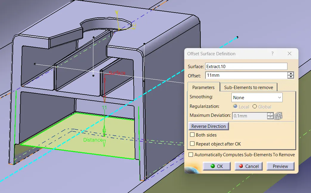
Fig 22. Offsetting the bottom of the innner wall.
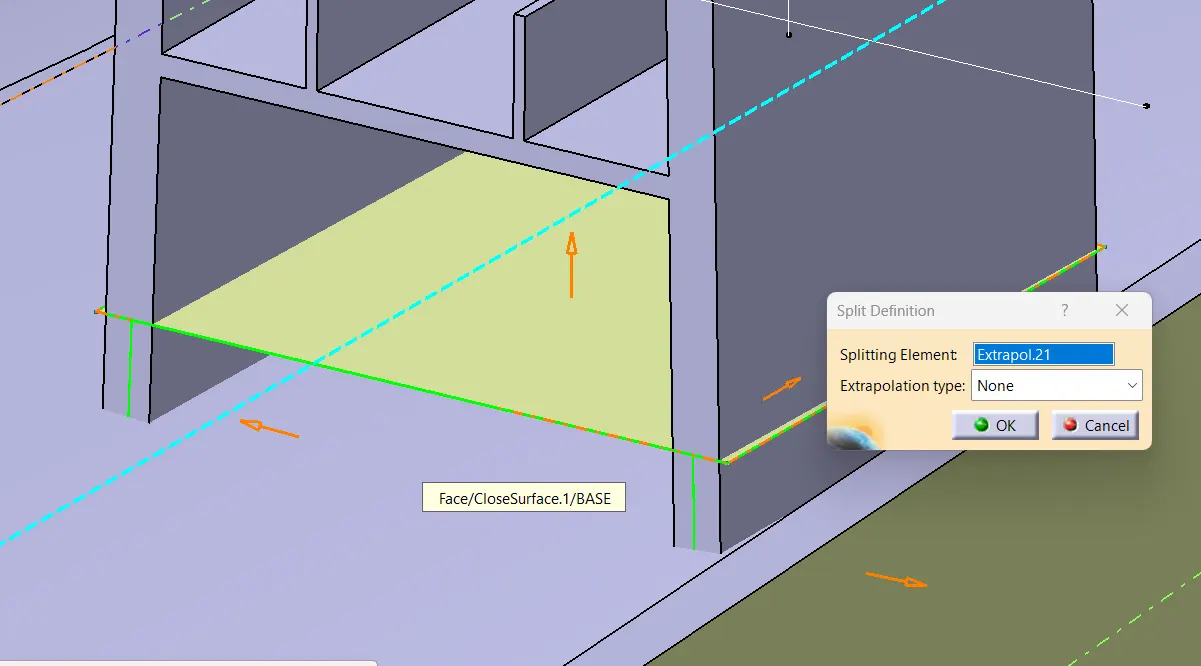
Fig 23. Split operation in part workbench is done to create the cut portion.
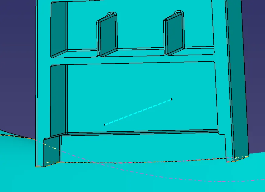
Fig 24. Dog house with bottom core.
The sketch for the top profile of the dog house is then created and pad operation is performed in part workbench. Then it is removed from the main part body using remove boolean operation.
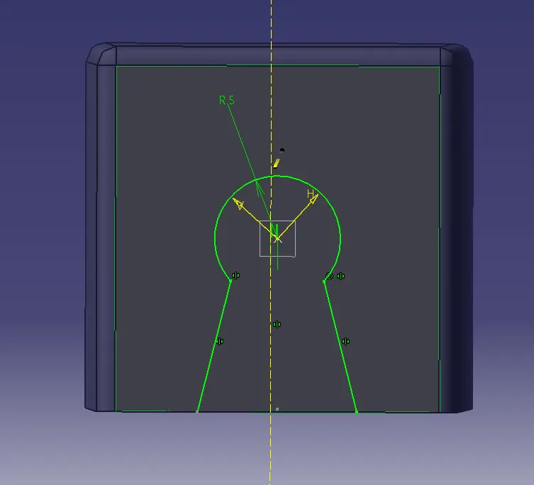
Fig 25. Sketch for top profile.
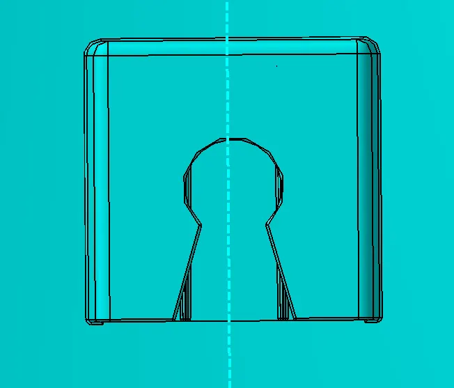
Fig 26. Top profile for dog house.
Edge fillets of 1.5mm are given at the outer edges and minimal fillet of 0.25mm is given for all the remaining edges.
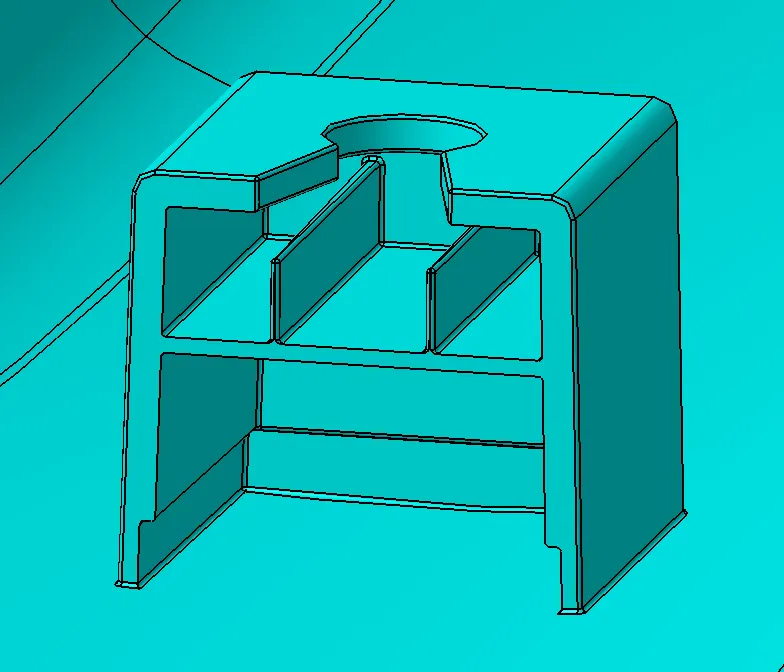
Fig 27. Final design of dog house.
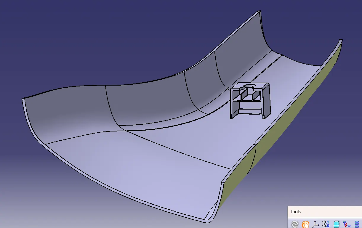
Fig 28.
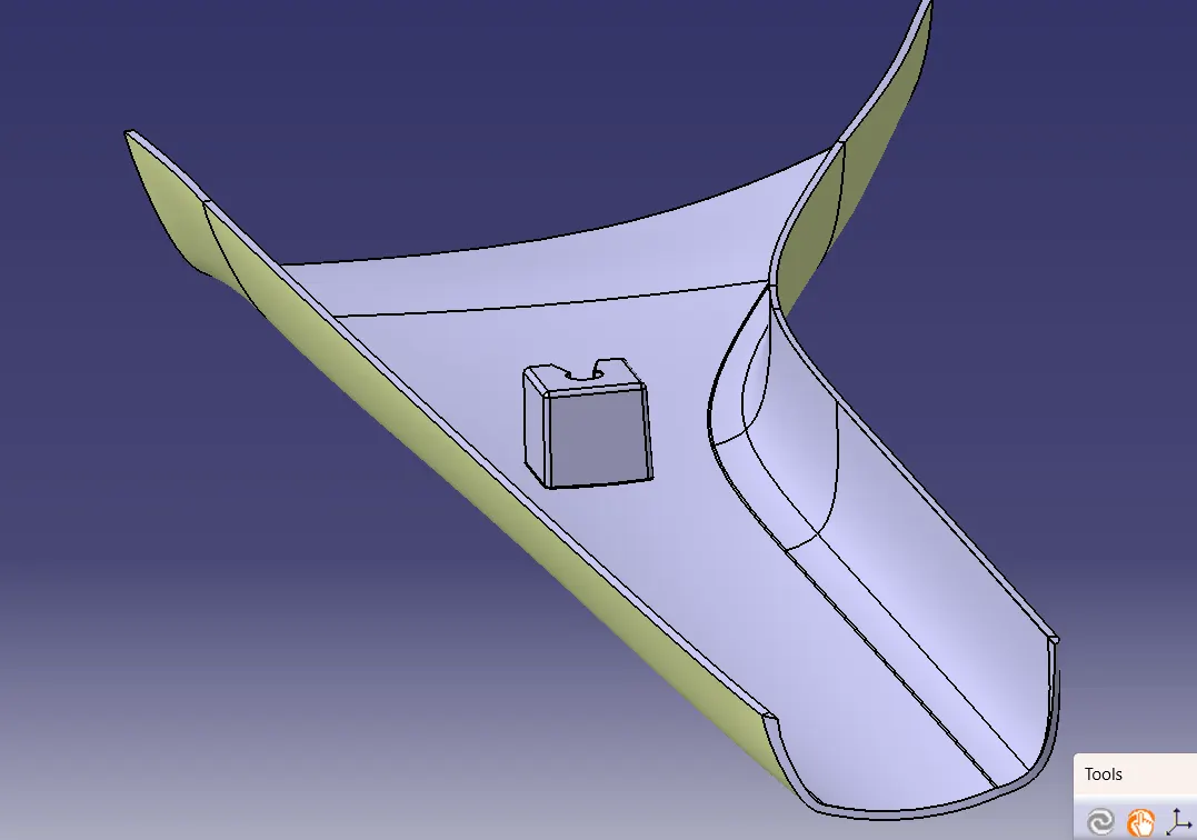
Fig 29.
Fig 28 & 29. Final design of A pillar with dog house.
DRAFT ANALYSIS
Draft analysis is done for the the outer surface of the dog house by using the main tooling axis as the tooling direction. The surfaces cleared the given 1.5° draft.
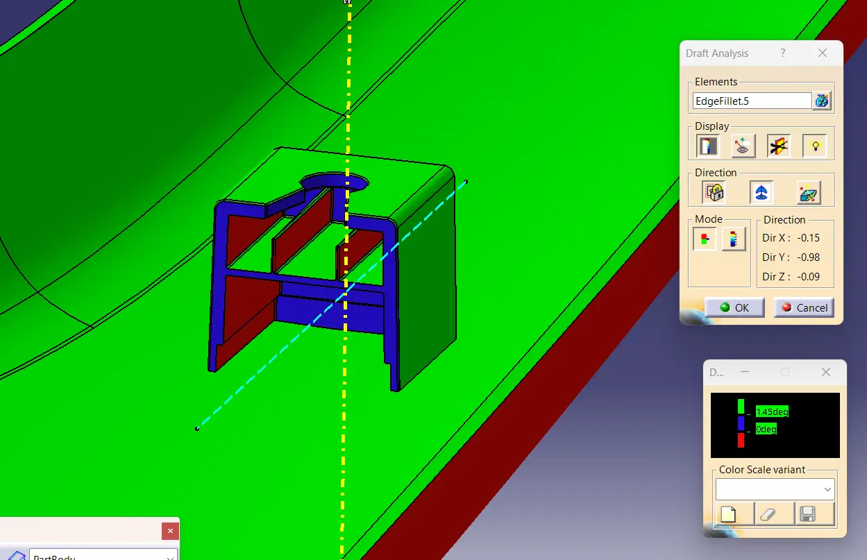
Fig 30. Draft analysis with main tooling axis.
Draft analysis is conducted with the side core axis for the inner portions of the dog house. All the regions inside have cleared the given 0.5° draft.
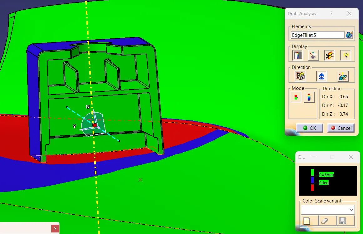
Fig 31. Draft analysis using the side core axi
Feature tree
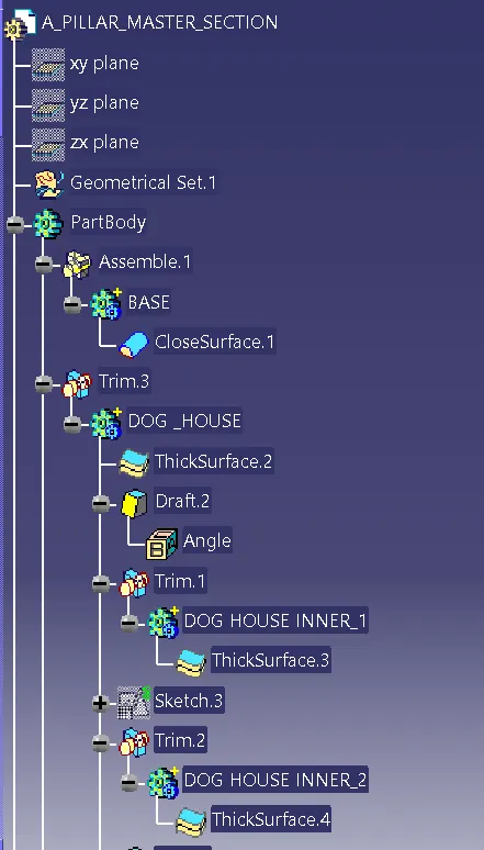
Fig 32.
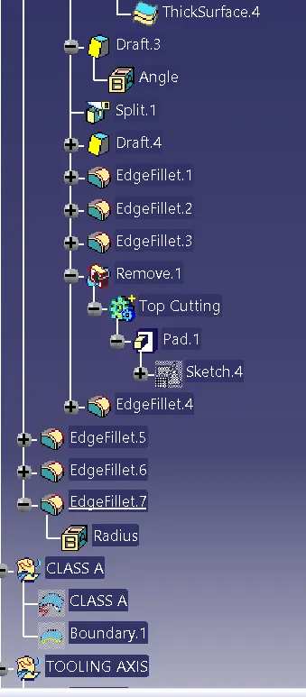
Fig 33.
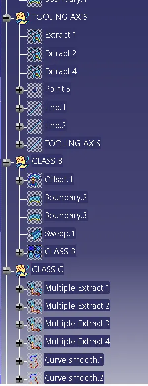
Fig 34.
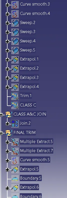
Fig 35.
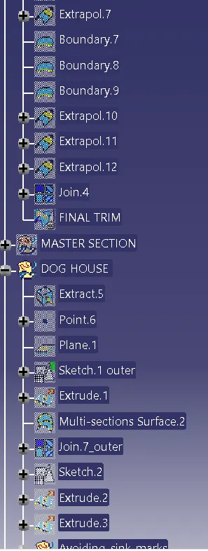
Fig 36.
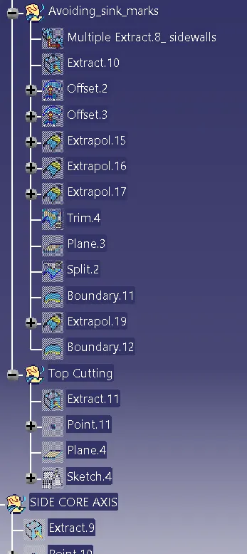
Fig 37.
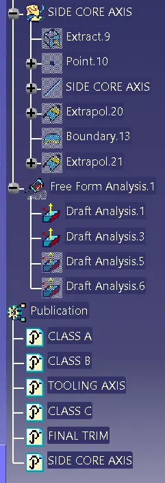
Fig 38.
Thank You.