Week 9 - Challenge 3 - Bumper
BUMPER DESIGN
In this challenge, a Bumper is designed using the given class A surface and performed draft analysis for the same.
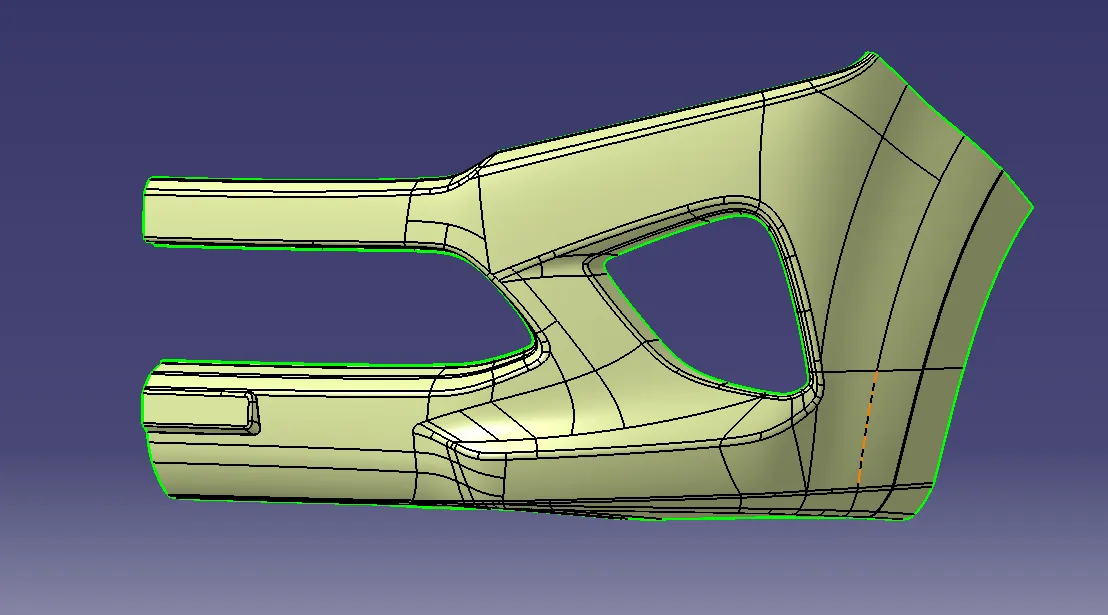
Fig 1. Class A Surface.
The given class A surface is checked for irregularities and gaps initially and found the surface is perfect.
Tooling Axis Creation
Since the surface is a complex one, a different method is used to create the tooling axis.
First, the surface is viewed with respect to X, Y and Z axes. While viewing, we were able to view the complete surface while viewing with the X direction.
So, a line is constructed along the X direction and considered as the tooling axis (temporarily).
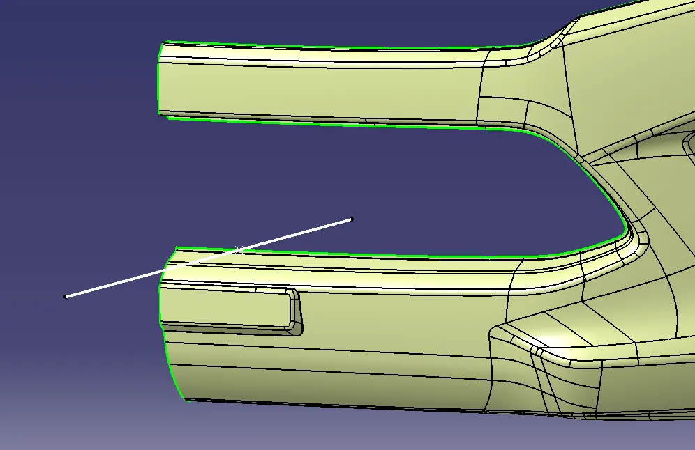
Fig 2. Tooling Axis.
Draft Analysis for Class A Surface
Draft analysis is done on the given class A surface using the considered tooling axis and checked whether the surface clears the draft.
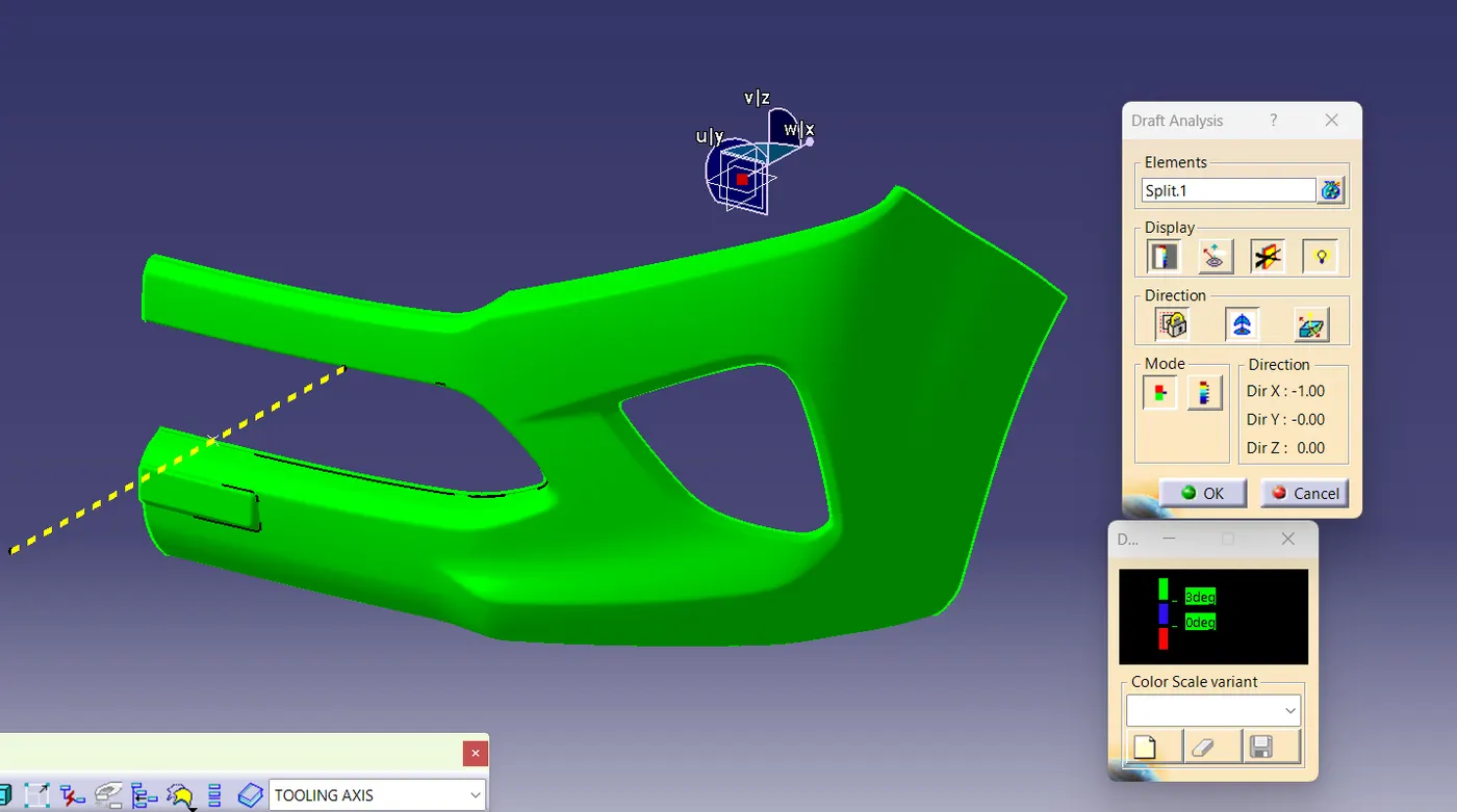
Fig 3. Draft Analysis on Class A surface.
It was found that the surface is clearing the draft. So, the line which is considered as the tooling axis can be confirmed as the tooling axis for the bumper.
Creation of Class B Surface
Here the surface is a complex one. So it is not possible to adopt the methods adopted in the previous challenges.
Here the Class A is offseted completely downwards by 3mm, which is the thickness of the bumper. While checking the offseted Class B surface, some fillet areas were missing.
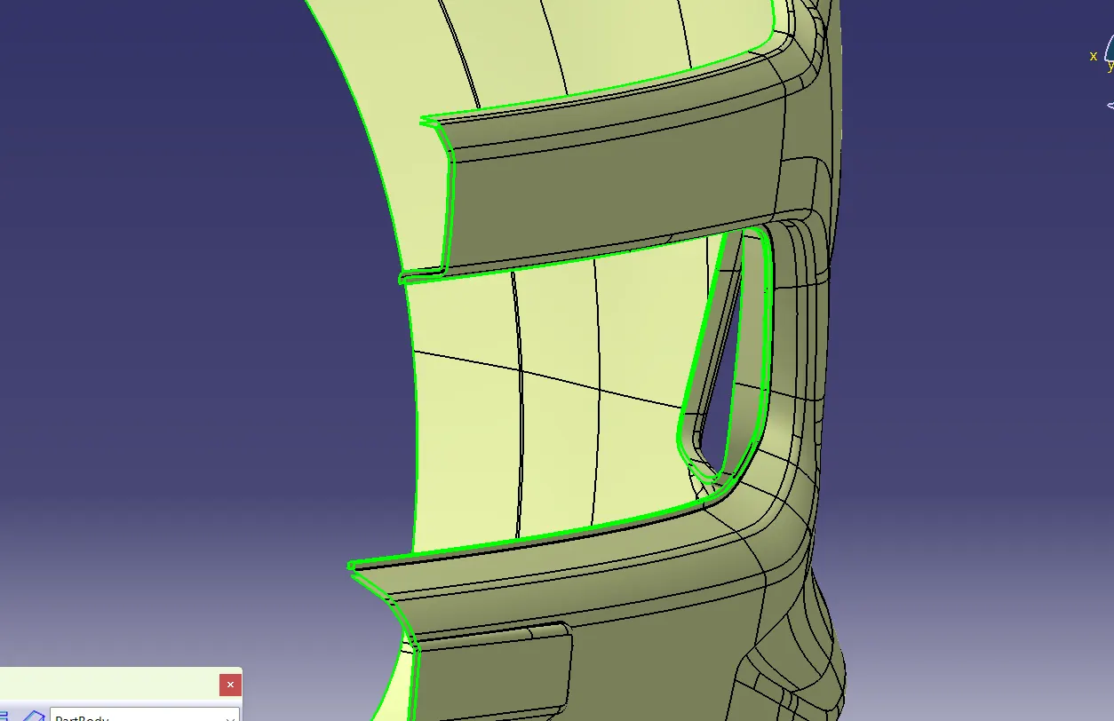
Fig 4. Class A is offseted by 3mm.
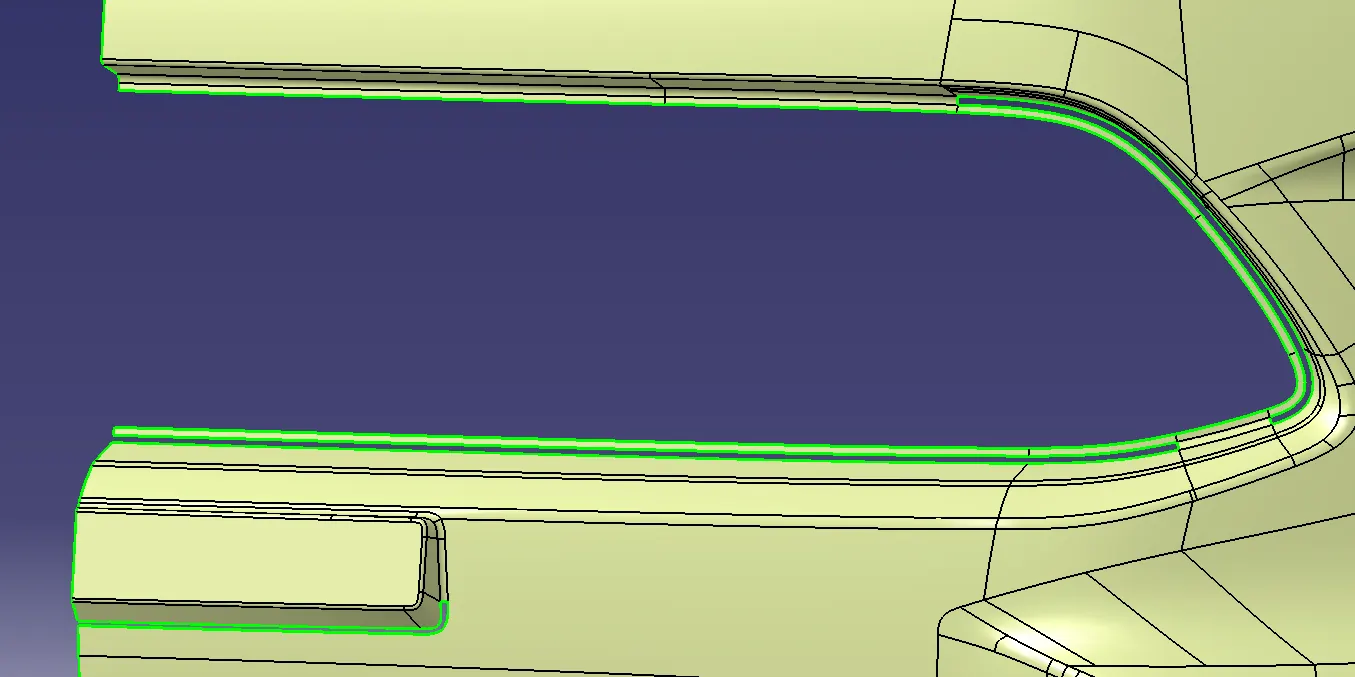
Fig 5. Missing fillets on offseted surface.
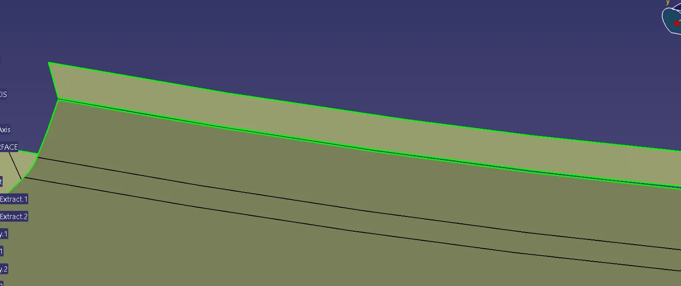
Fig 6. Missing fillet on top of Class B.
The empty spaces thus created on the offseted surface should be patched perfectly.
The missing surfaces were patched using the commands:
- Multiple extract
- Untrim
- Extrapolate
- Trim
- Split
- Join (use sub elements to remove inside the command box and select the surface).
It is not necessary to use all the above mentioned commands or only these commands. We can even patch the surfaces by using some these commands or using other commands. The commands mentioned here are the ones used in this challenge.
After providing the fillets, the Class B surface is got.
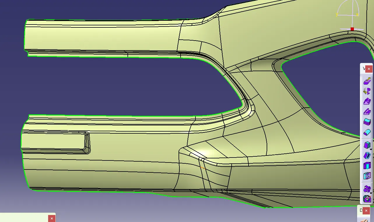
Fig 7.
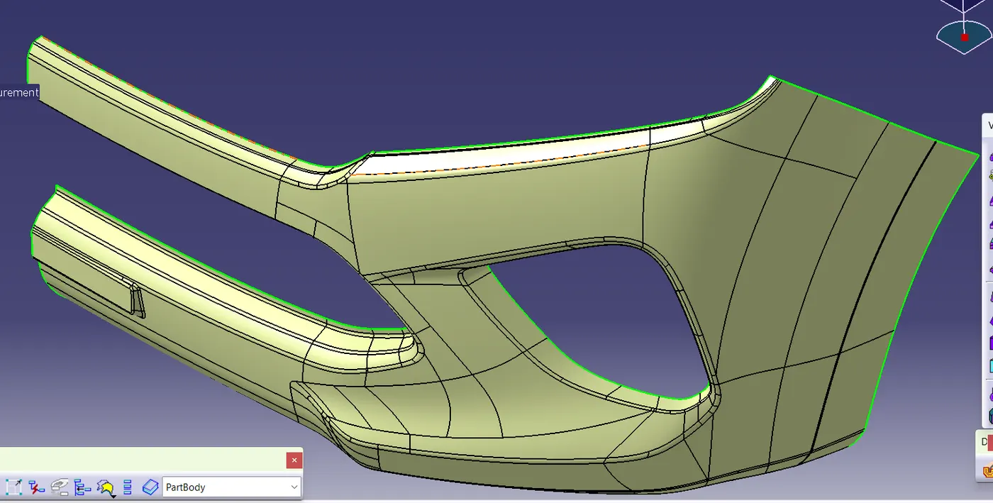
Fig 8.
Fig 7&8. Gaps of fillets were cleared on Class B surface.
Creation of Class C Surface
The surface which connects the Class A and Class B is Class C.
The C surface which connects the grille region and the centre half region are connected using "with draft direction" option in the Sweep command whereas the remaining boundaries are connected using "with reference surface" option of sweep command. In the first case, a draft angle of 3° is given and in the second case, C surface is created normal to the Class A since the surface of A comes parallel to the tooling axis.
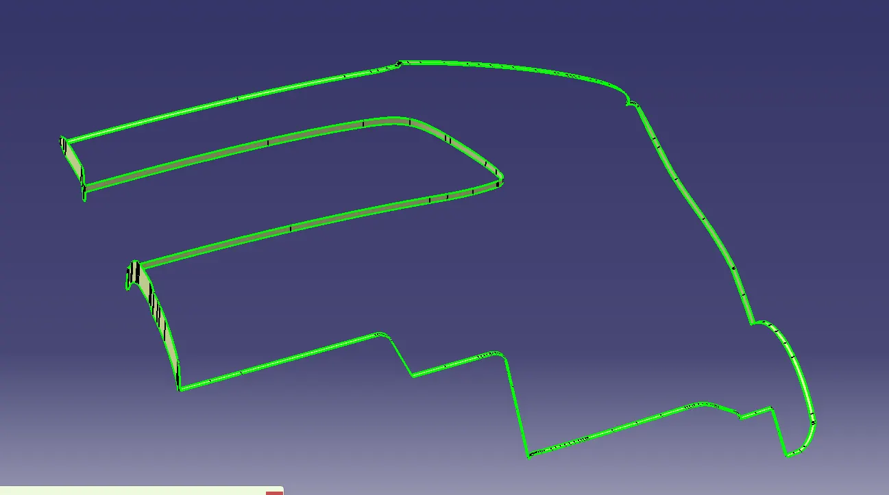
Fig 9. Class C Surface.
Final Trim
After creation of Class C, the Class A and Class C are joined together and then the new surface is trimmed with Class B surface.
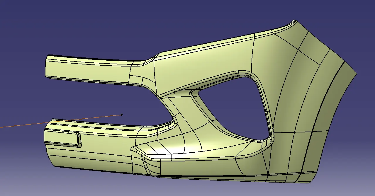
Fig 10. Part after final trim.
Creation of closed body
The part is then converted to a closed body using "Close Surface" command in part workbench and it is mirrored using "mirror" command fo the other half.
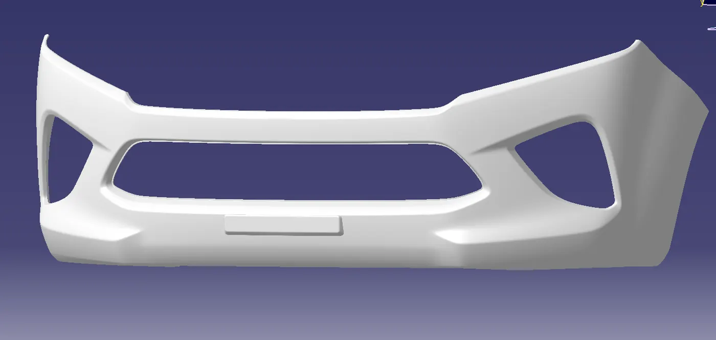
Fig 11. Part converted to closed body.
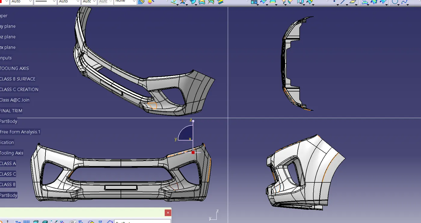
Fig 12. Different views of the part.
Draft analysis of the bumper
Draft analysis is done on the final bumper design with respect to the tooling axis and found the design is clearing the draft and the design is suitable for manufactuing.
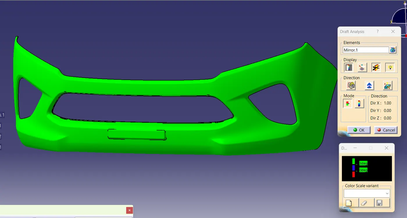
Fig 13. Draft analysis of Bumper.
Feature Tree
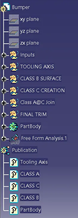
Fig 14. Tree Structure.
Thank you.