Week 12- Final project
FINAL PROJECT - DOOR TRIM LOWER PANEL
Aim
The aim of the project is to create a CAD model for the door trim panel using the given Class A surfaces and master sections like in the OEMs and Tier 1 companies.
Objectives
- Check the given Class A surface for irregularities and correct them if present.
- Create tooling axes for each given surfaces and check whether they clear the draft.
- Create Class B and Class C surfaces for each parts.
- Convert the surfaces into solid bodies in part workbench.
- Decide and attachment strategy and follow the master sections to create the required engineering features on the main subsrate and the surrounding parts.
- Perform draft analysis on the part model and check whether they clear the draft.
- Assemble the components together using proper constraints.
Given Data
The Class A surface of all the components and master sections were already given.
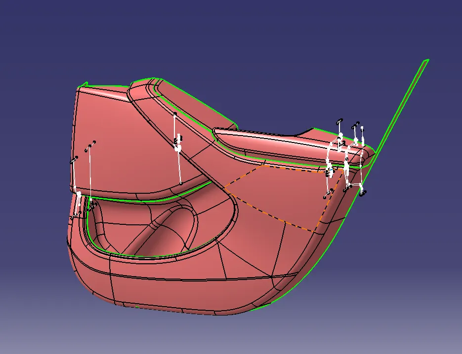
Fig 1. Class A surface of all components and master sections.
PROCEDURE
First, An assembly file is newly created with the name 'Door Trim Assembly' and the Class A surfaces of each components, the master sections and the push pins were placed under different part files created within the assembly file.
Fig 2. Assembly file and part files.
Arm Rest
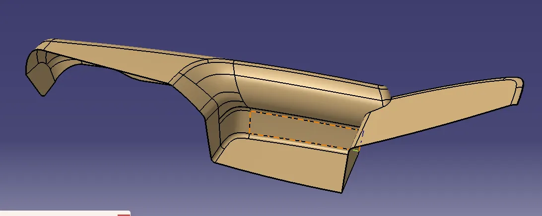
Fig 3. Class A Surface.
The Class A surface is checked for surface irregularities using Join command and one irregularity was found.
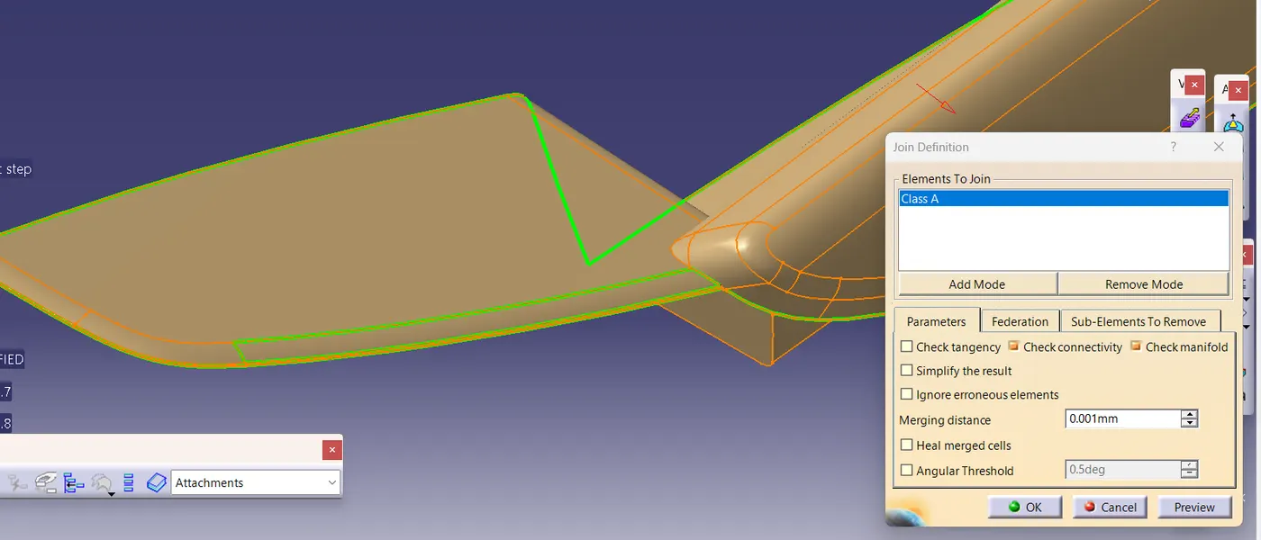
Fig 4. Irregularity check using Join command.
The Class A surface is modified using Extract, Extrapolate, Join and Trim commands.
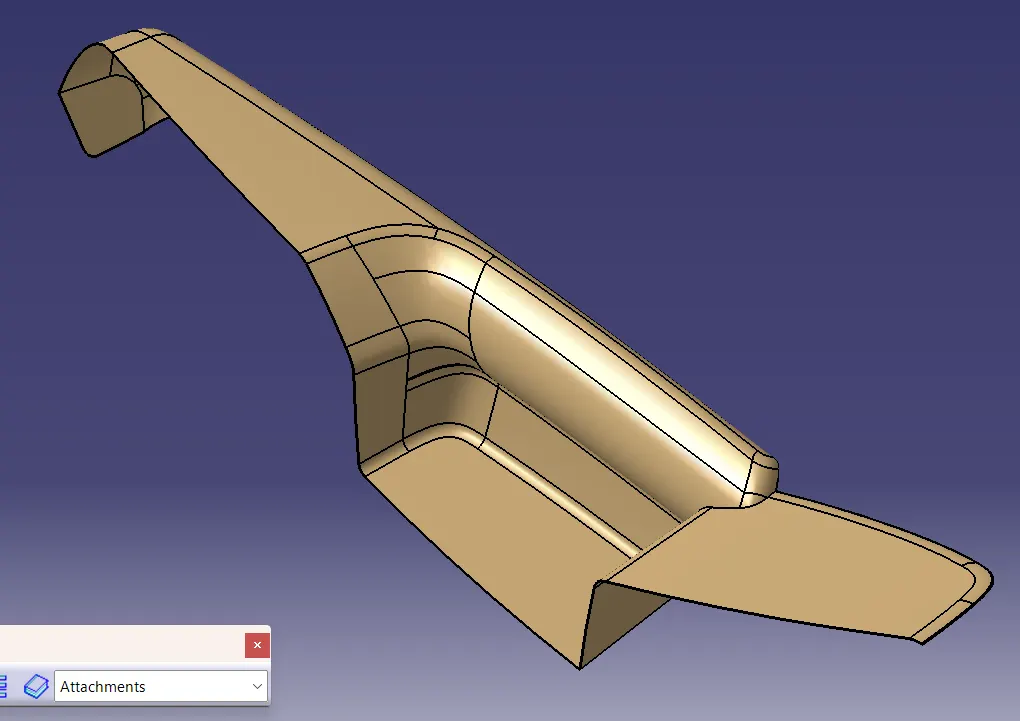
Fig 5. Modified Class A surface.
Creation of Tooling Axis:
For clearing all regions of the arm rest, two axes are required as tooling axis. One main tooling axis and a side core. The main tooling axis is created along the Z direction and the side core is created along the Y direction.
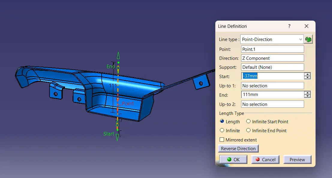
Fig 6. Main tooling axis for arm rest.
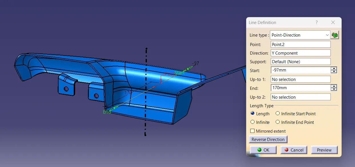
Fig 7. Side core axis for arm rest.
Feature Draft analysis is conducted on the Class A surface with both the axes. However, some regions were not clearing the draft with both axes. So Class A should be improved by the styling team and they should be informed about this, if we consider the case of an OEM. Here in this project we are neglecting this small failure and going on with the design.
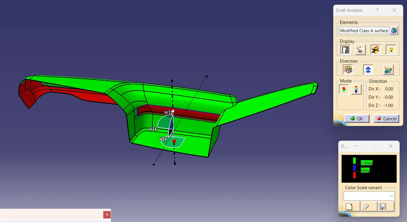
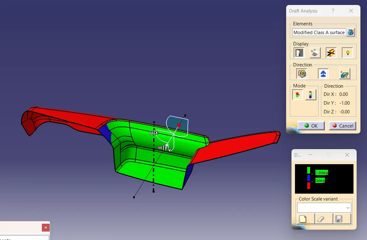
Fig 8 and 9. Draft analysis on Class A.
Creation of Class B surface:
The Class B surface is created by offseting the Class A surface by 2.5mm. From the master section, we found that the thickness of the surface is 2.5mm.
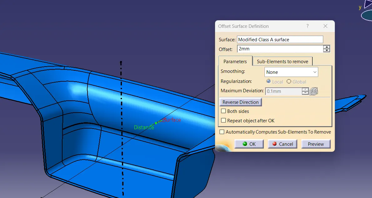
Fig 10. Creation of Class B surface by offseting Class A.
After offsetting, some areas were missing in the newly created surface. Such portions were filled using the commands boundary, extract, sweep and blend and the Class B surface is created.
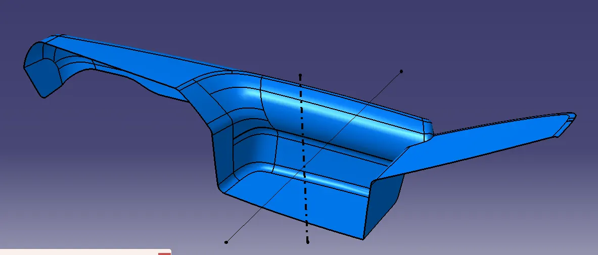
Fig 11. Class B surface.
Creation of Class C surface:
Class C is created from Class A boundary. In most of the regions sweep command is used for creation of Class C surface with a draft angle of 3º. In some regions where sweep becomes imperfect, we use commands like multi section surface and blend.
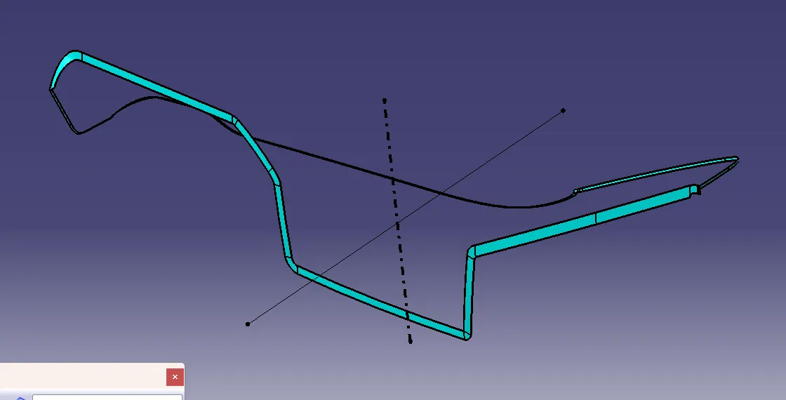
Fig 12. Class C surface.
Creaton of Closed body:
Class C is joined with Class A using Join command and this joined part is trimmed with B surface using Trim operation. Thus closed surface is obtained. For converting this surface to a closed body, we use the Close Surface Command in the part workbench.
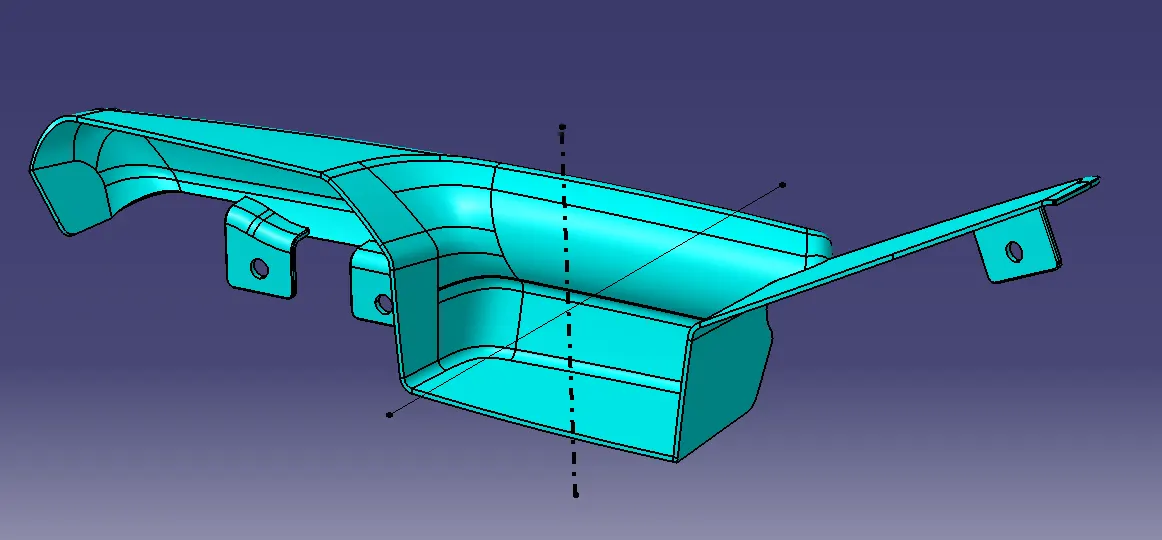
Fig 13. Closed body. (Flanges were not made at this stage. They were added later).
Draft analysis:
Draft is a taper applied to the faces of the part that prevent them from being parallel to the motion of the mold opening, thus facilitating the smooth ejection of the part from the mold without causing any damage.
Draft analysis is performed on the Closed body. As menioned in the case of Class A, a region fails to clear the draft due to the fault in the Class A design by the styling team. Here we are neglecting the fault.
Fig 14. Draft analysis using the main tooling axis.
Fig 15. Draft analysis using the side core axis.
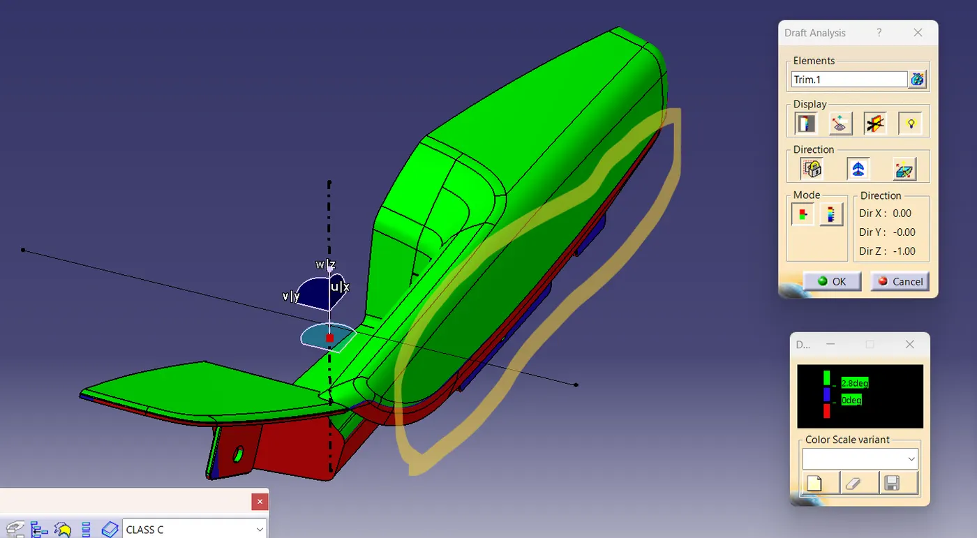
Fig 16. The red region inside the yellow marking failed in both analyses.
The steps such as creation of Class B and Class C, trimming them together, converting the final trim to a solid body are repeated for main substrate, map pocket and bottle holder.
Main Substrate
The given Class A surface is checked for gaps or other faults. But no such defects were present.
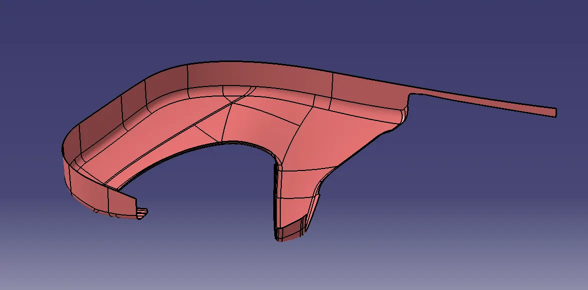
Fig 17. Class A surface.
The tooling axis was created along the Y direction.
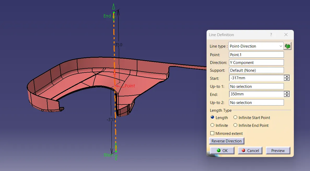
Fig 18. Tooling axis creation.
Draft analysis is conducted on the class A surface and it was found that the part was clearing 3° draft.
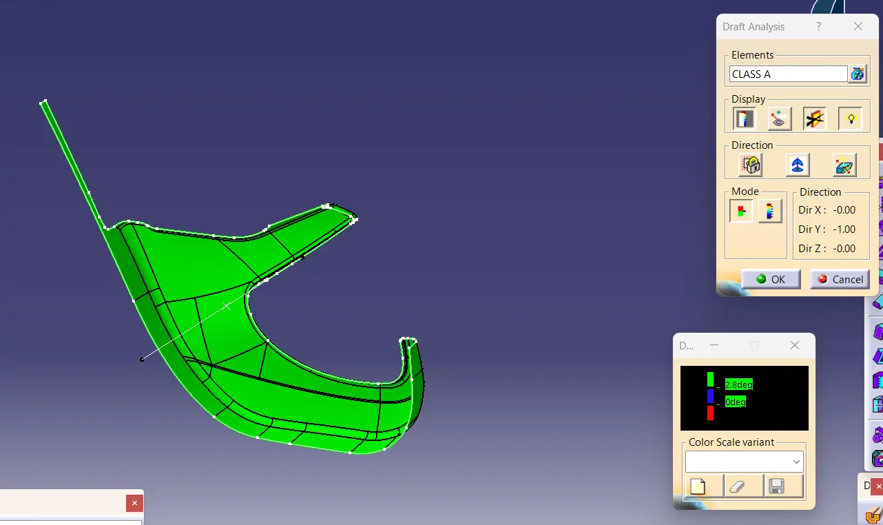
Fig 19. Draft analysis on Class A.
Class B surface was created by offseting the Class A surface by 2.5mm.
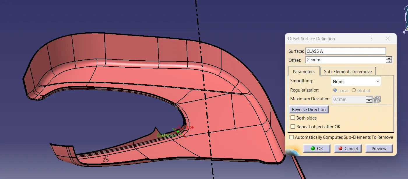
Fig 20. Class B surface creation.
The Class C surface was created using Sweep command from Class A surface.
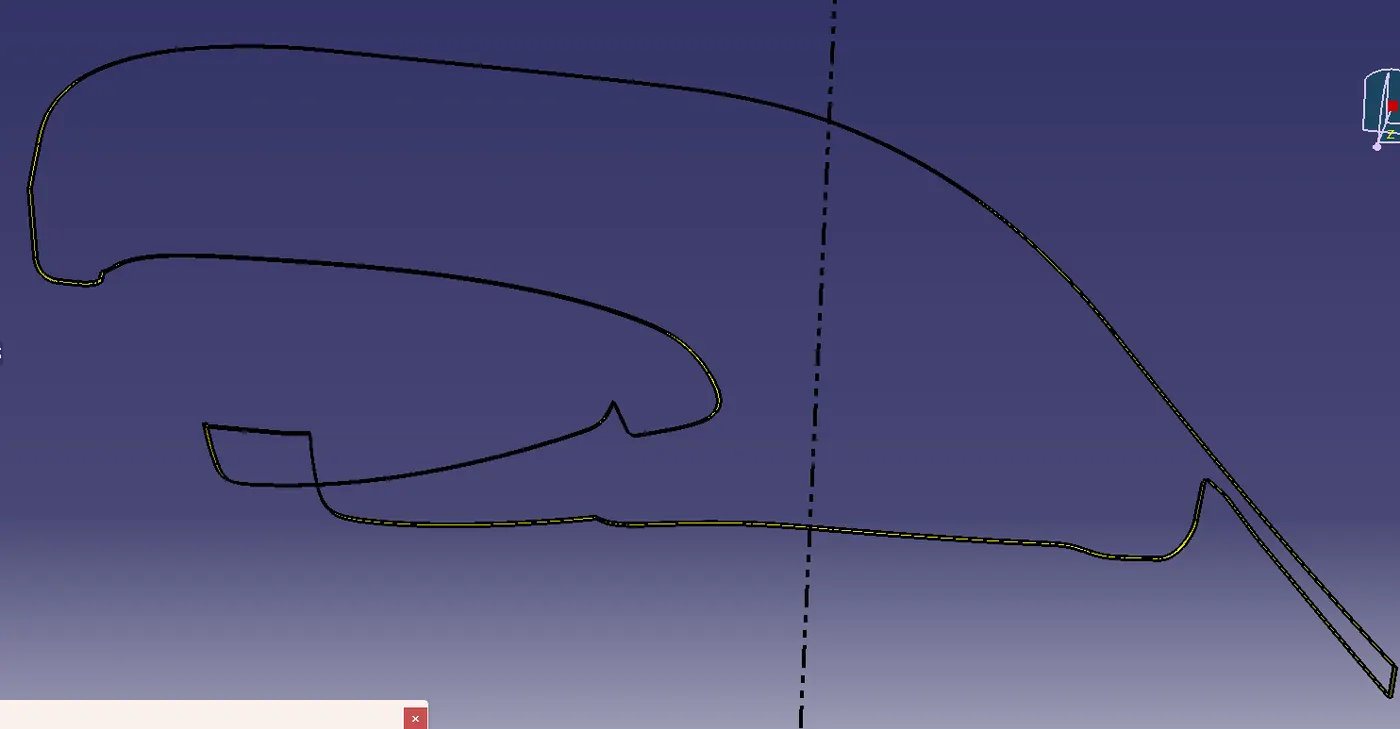
Fig 21. Class C surface.
After the final trim, solid body was created using Close surface in the part workbench.
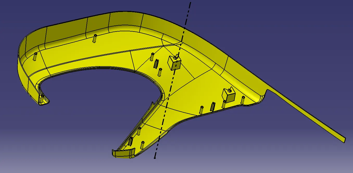
Fig 22. Solid body creation. (Dog house, heat stakes and locators were not created at this stage. They were added later).
Draft analysis was done on the closed body.
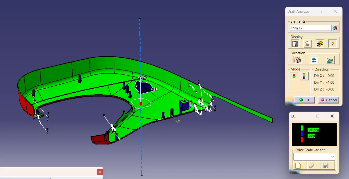
Fig 23. Draft analysis.
Map Pocket
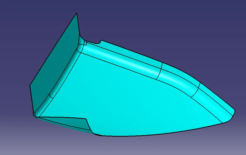
Fig 24. Class A surface.
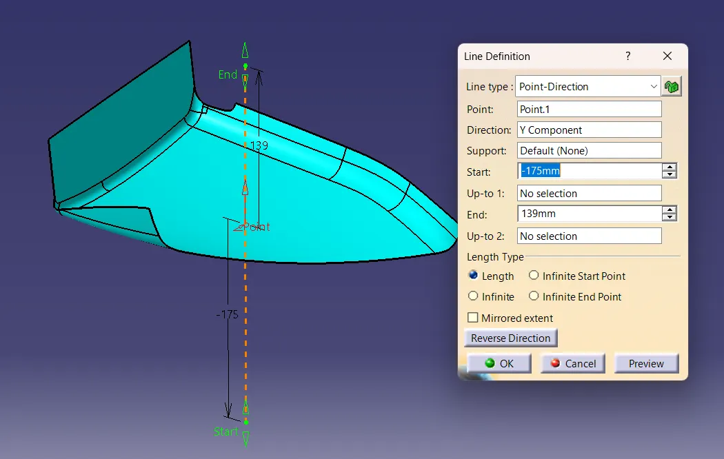
Fig 25. Tooling axis creation.
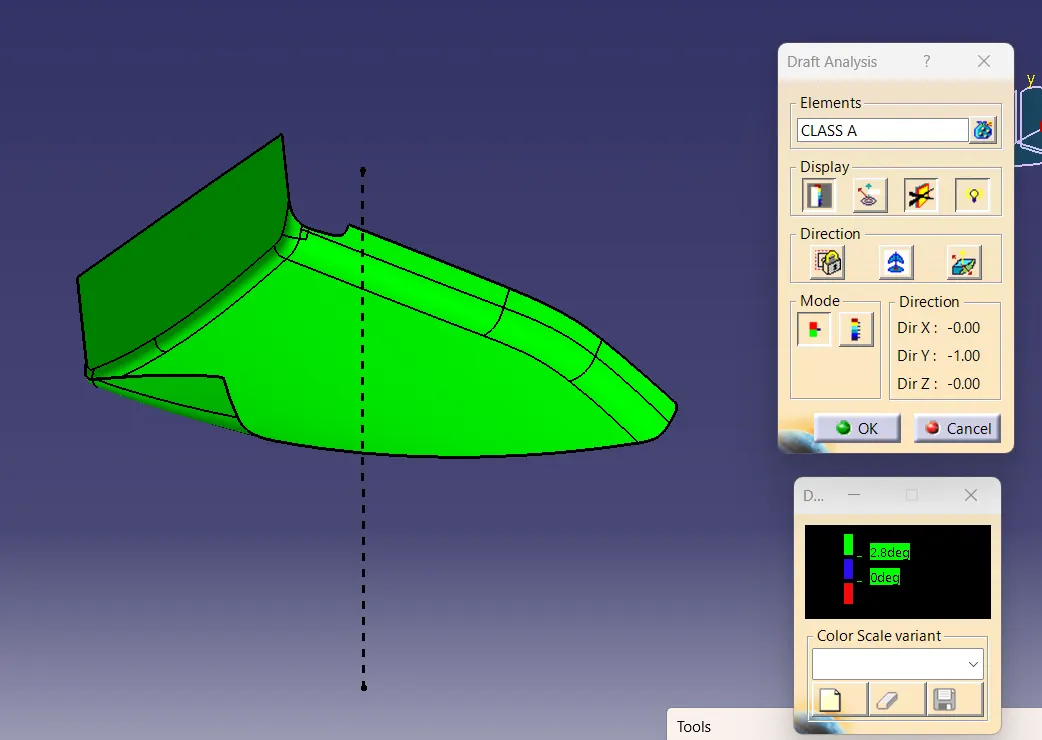
Fig 26. Draft analysis on Class A surface.
Class A surface was offseted by 2.5mm for the creation of Class B surface. A small region was missing in he newly offseted surface. It was cleared using multi section command and join command.
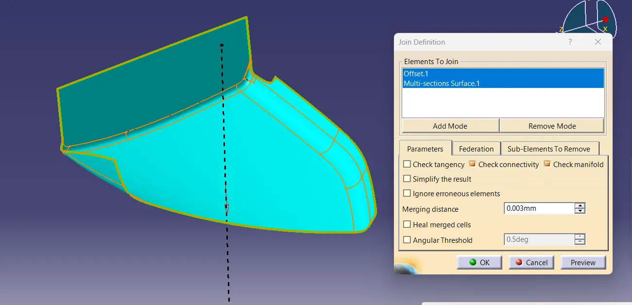
Fig 27. Class B creation.
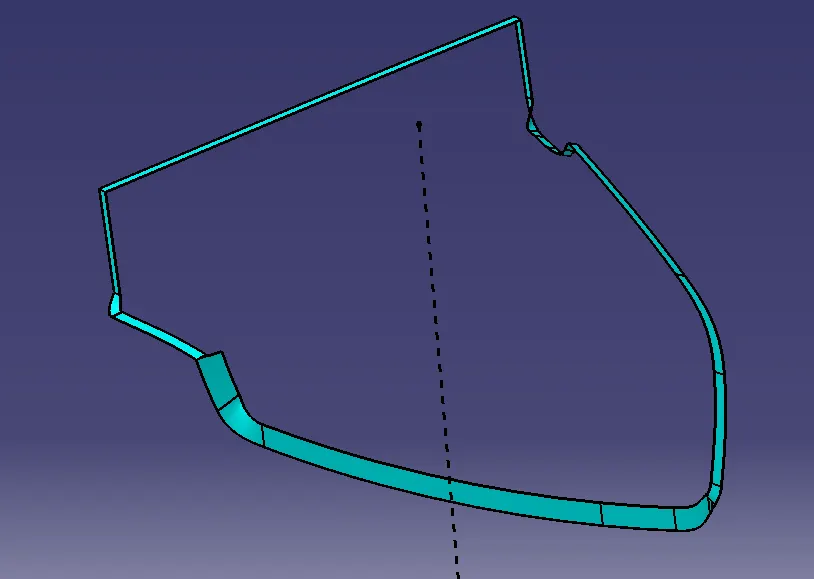
Fig 28. Class C surface.
Class A and C is joined together and trimmed with Class B. Then the final trim part is converted into a solid body using Close Surface command in part workbench.
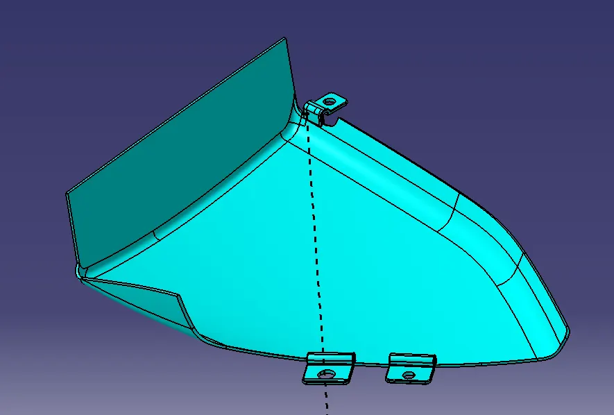
Fig 29. Solid body (Flanges were not created at this stage. They were added later).
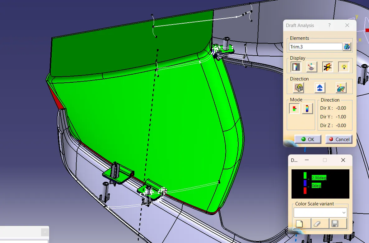
Fig 30. Draft analysis.
Bottle Holder
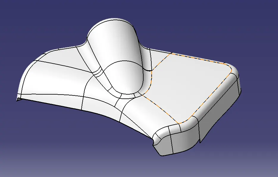
Fig 31. Class A surface.
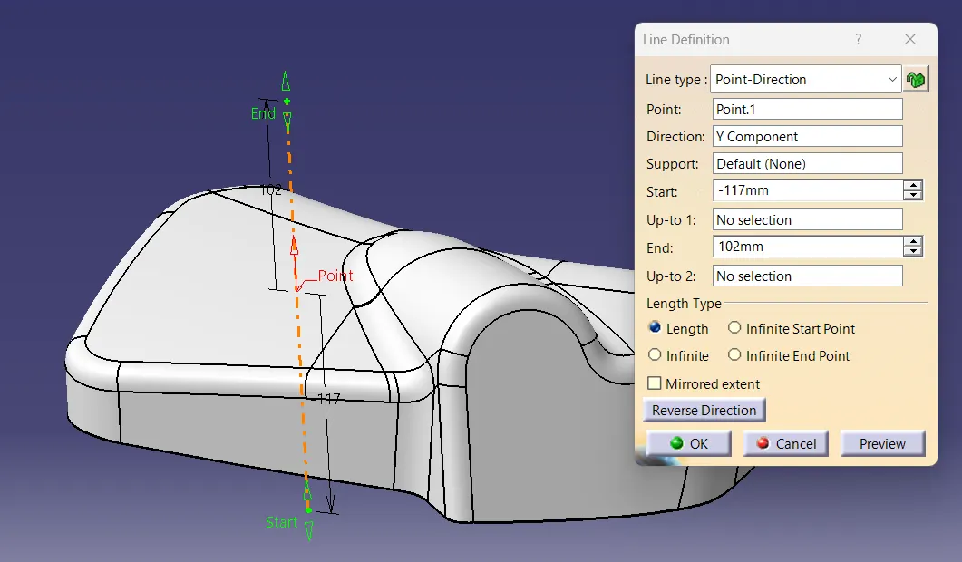
Fig 32. Tooling axis creation.
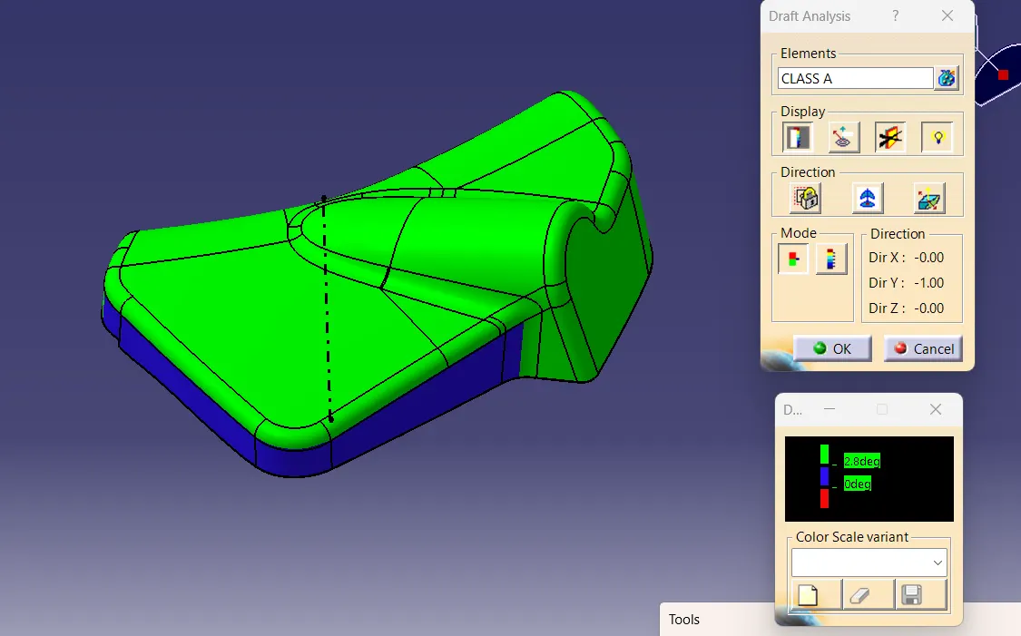
Fig 33. Draft analysis on Class A surface.
The Class A surface was offseted by 2.5mm to create Class B surface and Class C surface was created by using sweep command from the Class A surface.
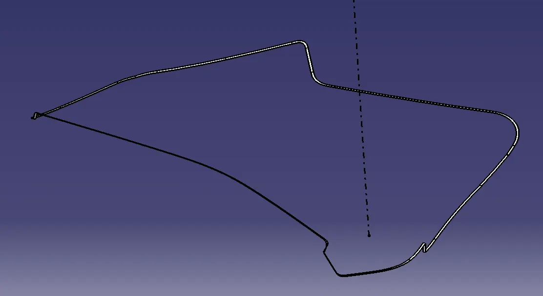
Fig 34. Class C surface.
Class A and Class C surface are joined using join command and trimmed with Class B surface using trim command. The trimmed part is converted into a solid body using Close surface command in part workbench.
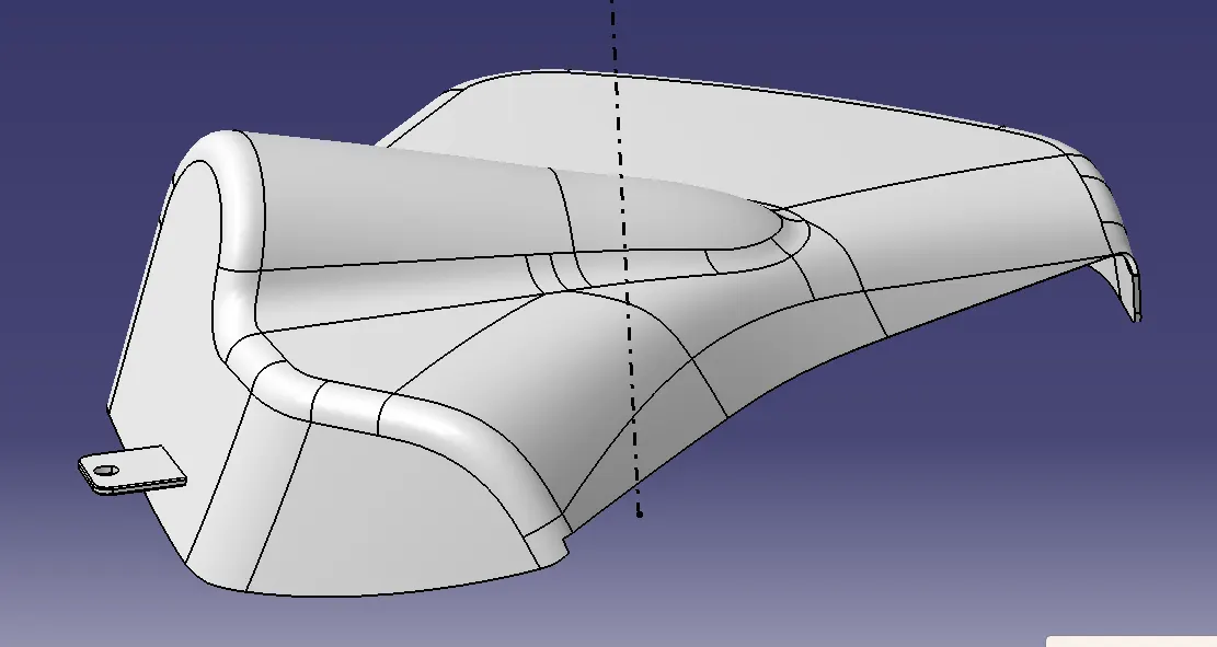
Fig 35. Solid body. (Flanges were not created at this stage. They were added later).
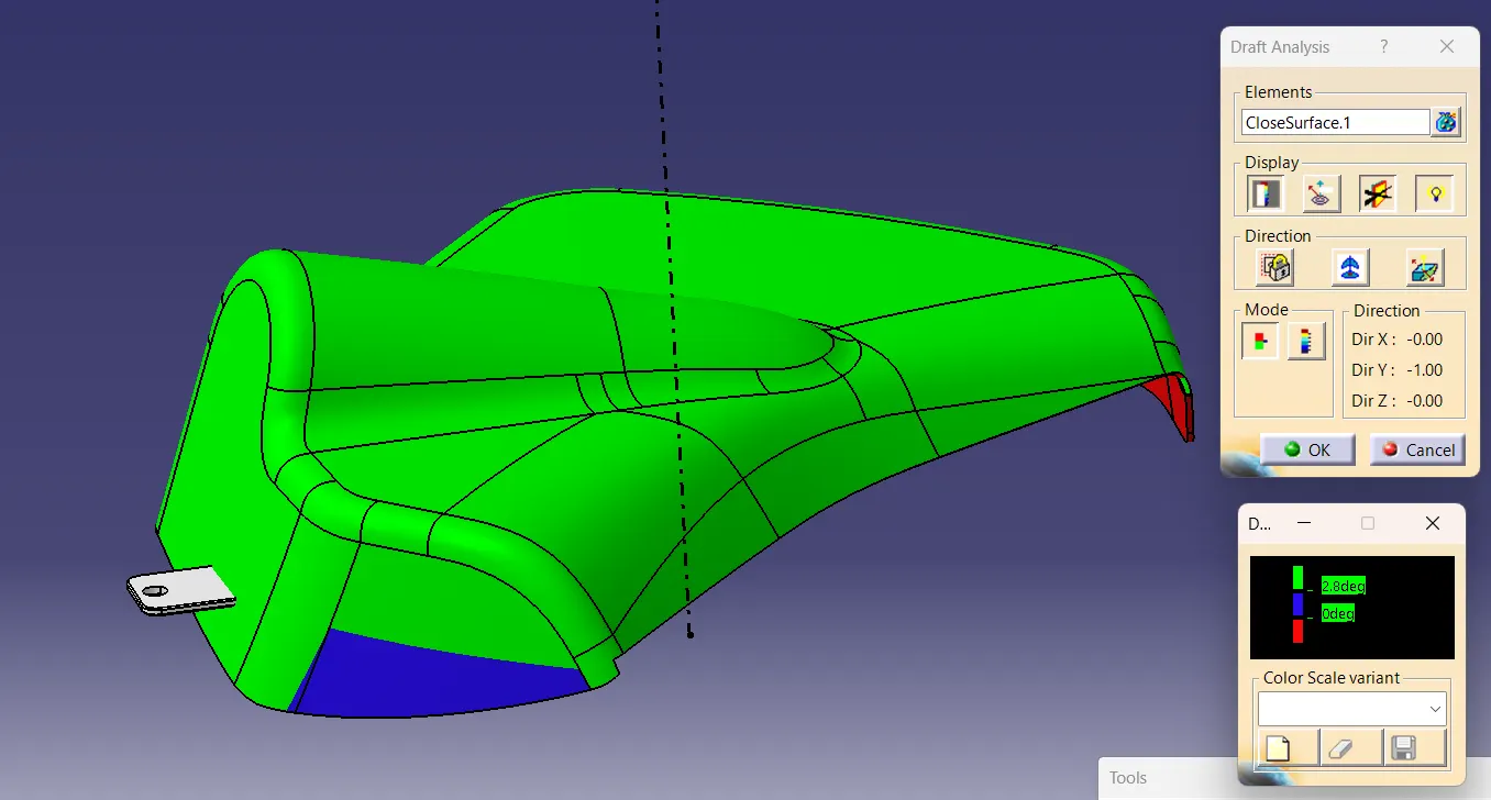
Fig 36. Draft analysis on solid body.
Creation of Attachments
The attachments are created for joining the parts together. The attachment features used here are heat stakes, locators, dog house and flanges.
Dog House
Dog House is a feature used in plastic design which helps to avoid sink marks. This is the primary function of a dog house.
It is also useful to house various attachment features like screw boss, locators, push pins etc. For instance, if we need a screw boss 100mm away from the B surface, creating a 100mm screw boss is not feasible. So we create a dog house on the B surface and attach the screw boss on the dog house.
In this project, the dog house is designed to house the push pin for attachment. A slot is given at the top of the dog house for fixing the push pin.
Design rules for creating dog house:
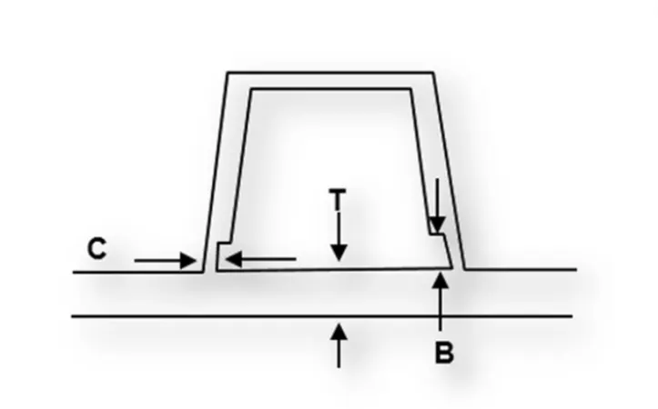
Fig 37. Parameters for dog house.
- Dog house thickness at intersection of part wall (C) should be 40% or less than the main wall thickness.
- Height B should be between 3-6mm.
- Width of dog house should be minimum 12mm.
- Minimum height of dog house should be 6mm. Less than 6mm causes weak steel condition.
- There should be a minimum draft of 1.5° for the outer surface and 0.5° for the inner surface.
Creation of Dog House:
A portion from the surface of the main substrate is extracted and a point is created on the location where we intend to fix the dog house.
An axis system is given at the point and the sketch for the dog house is done on the XY plane of the axis system.
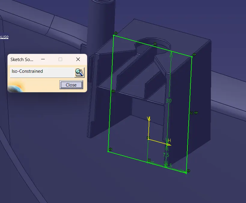
Fig 38. Sketch for dog house.
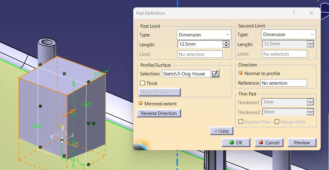
Fig 39. Pad operation.
The closed solid which obtained after Pad operation is converted into open part using shell command and a thickness of 2mm is given for the outer wall.
A draft of 1.5mm is given for the outer wall.
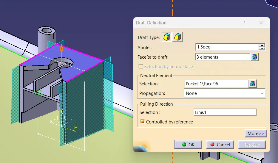
Fig 40. Draft on outer walls. (The front wall of the dog house should also be drafted. Here, it is done as the next step).
For clearing the inner portion of the dog house, we create tooling axis called side core normal to the inner surface.
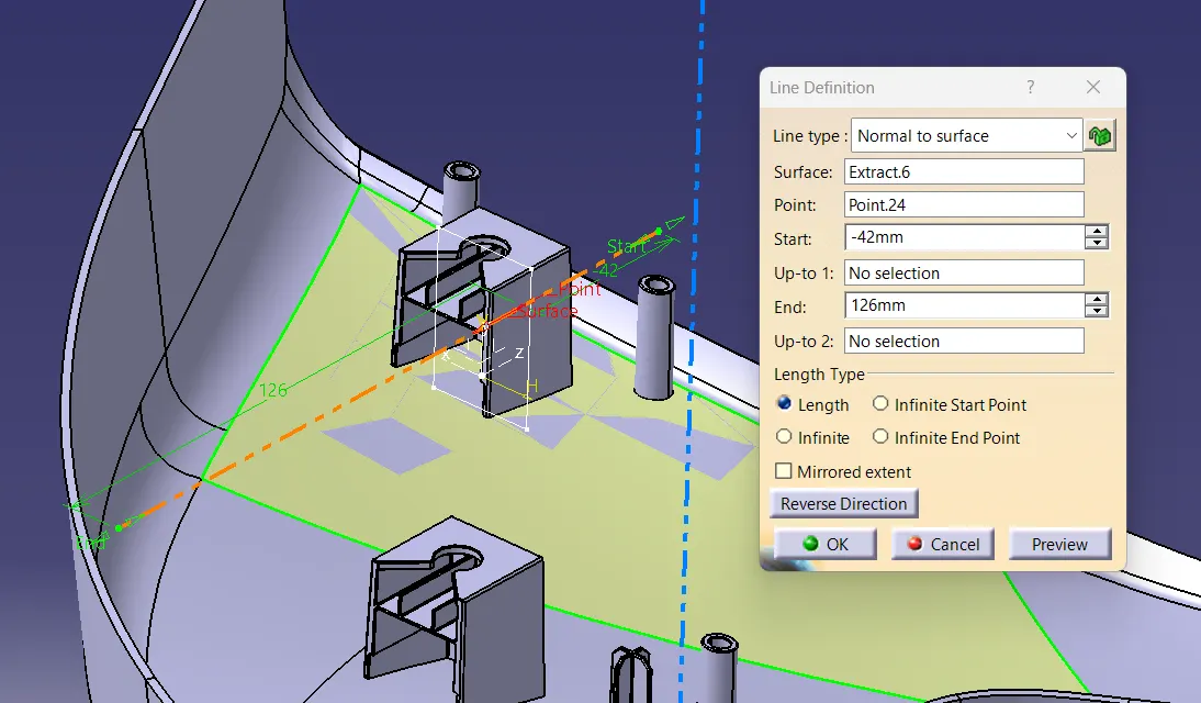
Fig 41. Creation of side core.
The inner walls of the dog house is constructed by using offset command and extrude commands. The thickness of the inner wall is 1mm.
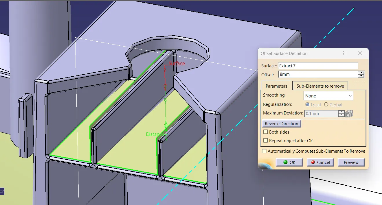
Fig 42. Inner wall creation.
A draft of 0.5° is given for the inner region of the dog house with the side core axis as the pulling direction.
The C portion of dog house is created by extracting and offseting the respective inner walls and then trimming them together. The trim is split with the part body using split command in the part workbench.
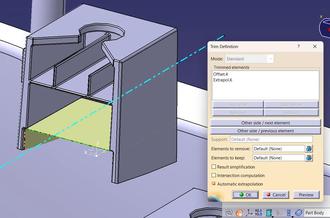
Fig 43. Creation of C portion.
A slot is created on he upper side of the dog house for attaching the push pins. From the sketch, the pocket command is used to create the slot.
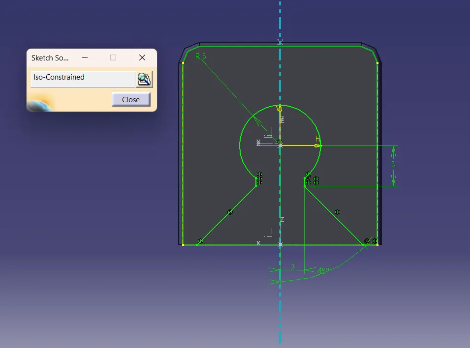
Fig 44. Sketch for dog house upper slot.
Feature draft analysis is conducted on the dog house. For the outer side, main tooling axis is the pulling direction and for the inner region, side core axis is the pulling direction. The part clears the draft analysis.
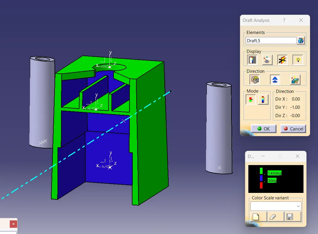
Fig 45. Draft analysis with respect to main tooling.
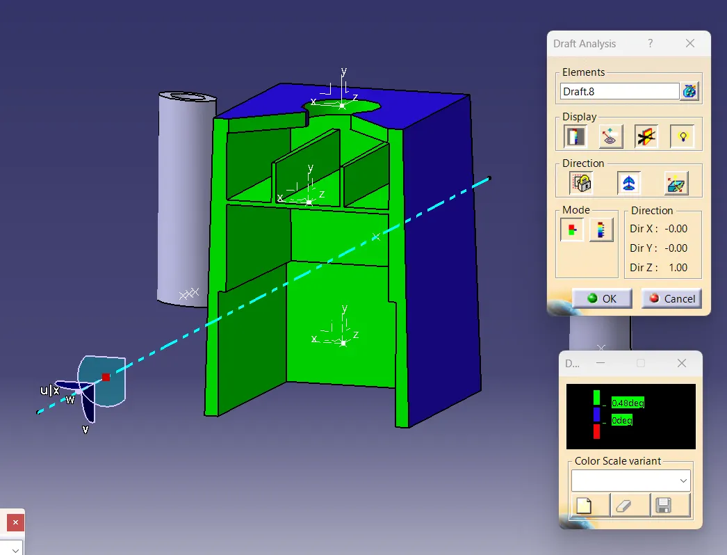
Fig 46. Draft analysis with respect to side core.
The dog house is fixed on the other locations by using translation feature. They are attached to the main part body by using boolean operation union trim.
Heat stakes
Heat staking is an assembly method that uses controlled melting and reforming of a pastic stud or boss to capture or lock another plastic material or metal component of an assembly in place. The plastic stud protrudes through a hole in the component to be locked in place.
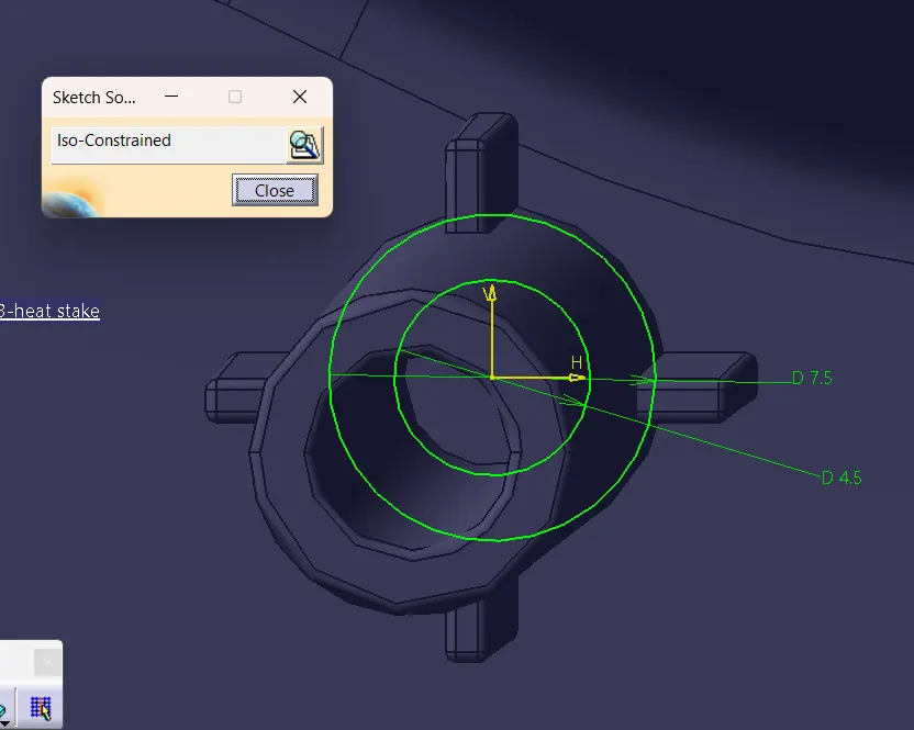
Fig 47. Sketch.
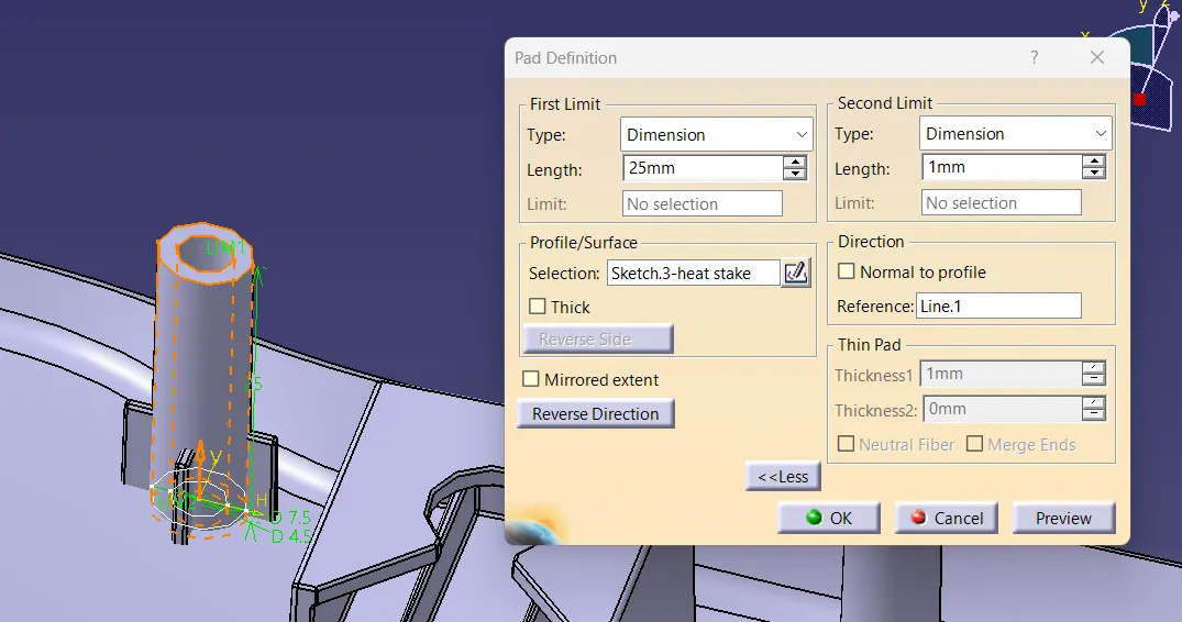
Fig 48. Pad operation for heat stake.
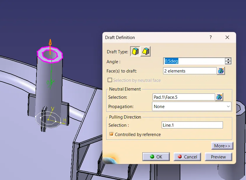
Fig 49. Draft operation.
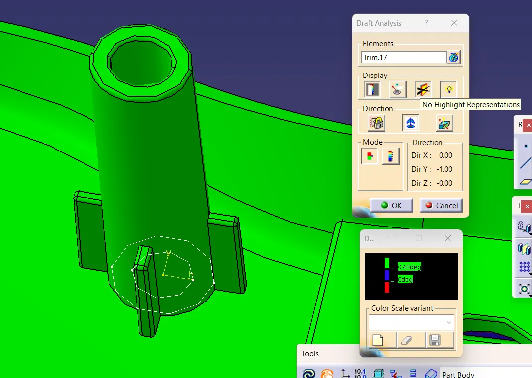
Fig 50. Draft analysis on Heat stake.
The heat stake design satisfies the 0.5° draft.
Supporting ribs are also provided along with heat stakes for additional support. The heat stakes are transferred to other points by using translation command and they are attached to the main part body by using either one of the boolean operations union trim and assemble depending on the location.
Locators
The 3-2-1 principle is adopted for part to part fixation in automotive industry. According to this principle, a workpiece has 12 degrees of freedom.
- Translational movement along X and -X axes.
- Translational movement along Y and -Y axes.
- Translational movement along Z and -Z axes.
- Rotation along X axis in clockwise and anticlockwise direction.
- Rotation along Y axis in clockwise and anticlockwise direction.
- Rotation along Z axis in clockwise and anticlockwise direction.
To fix two components together, at least 11 degrees of freedom should be arrested. In order to achieve this, we create 4 way locators. The height of locators should be greater than that of heat stakes.
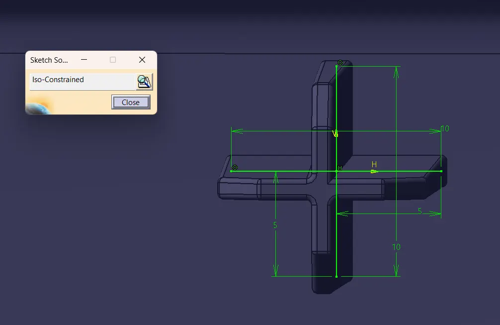
Fig 51. Sketch.
Fig 52. Pad operation.
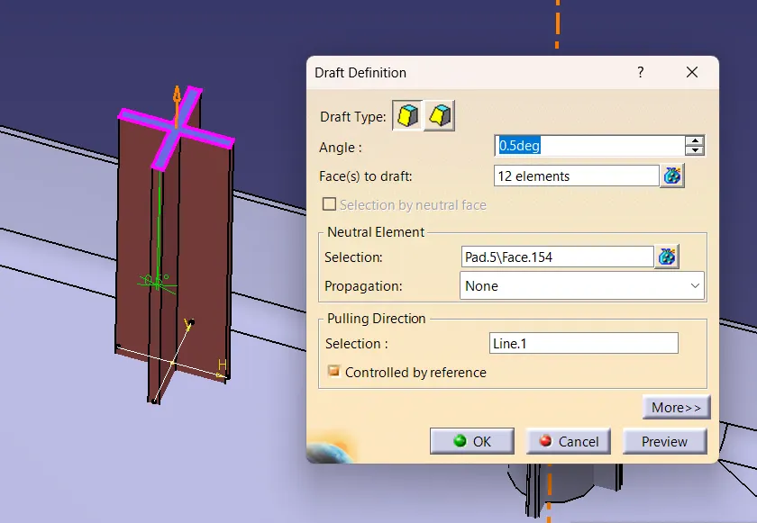
Fig 53. Draft operation.
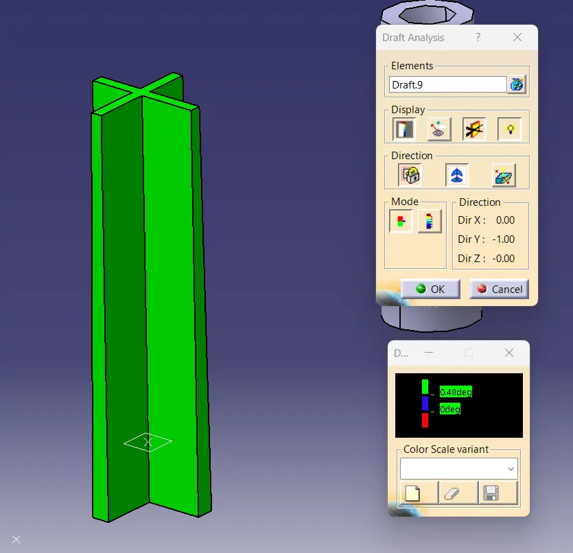
Fig 54. Feature draft analysis.
The design of the locator satisfies the draft analysis.
The locator is copied to the other points by copying the part and using translation feature. It is then attached to the main body using the boolean operation Union trim.
Flanges
Flanges are the joining feature that is used to assemble different components. Here we create flanges by following the master section. Flanges have a thickness of 2.5mm and they are given a draft of 0.5°.
For designing the flange for the arm rest:
- The master section is considered and a line is plotted along the master section.
- The line is extruded along X axis for the horizontal portion of the flange.
- For the vertical portion, sweep command is used, with subtype "with reference surface" in the profile type "explict".
- Both the vertical and horizontal potion is trimmed together using trim command.
- The trim surface is thickened using thicken command in the part workbench.
- Fillets are given following the master section's fillet radius.
- The hole at the flange is created using pocket command.
- A draft of 0.5° is given for the flange.
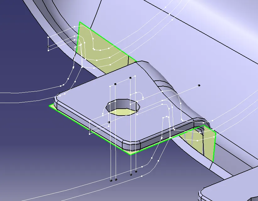
Fig 55. Vertical and Horizontal surface of master section after trim.
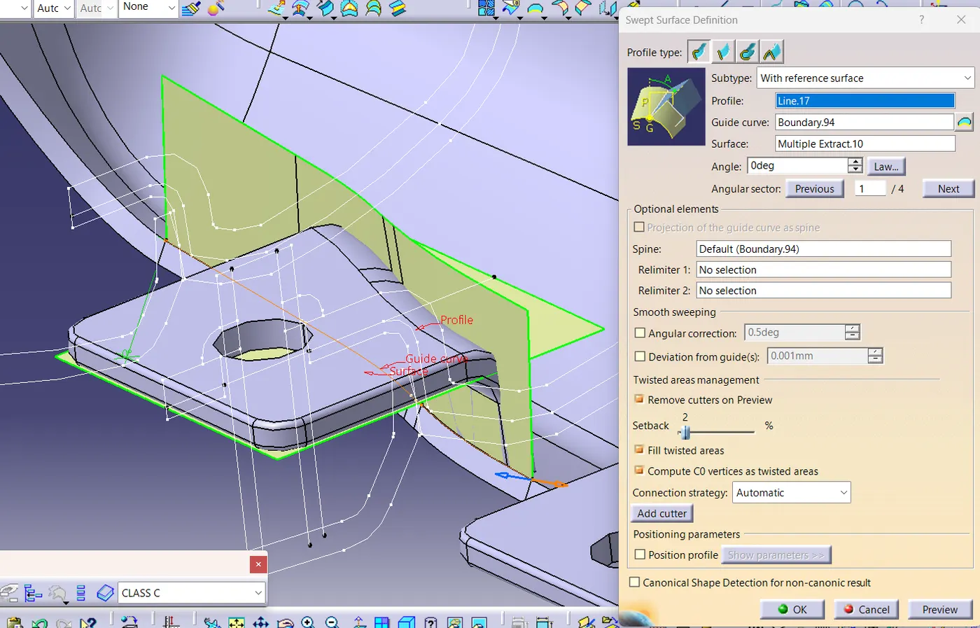
Fig 56. Sweep operation for creating the vertical surface.
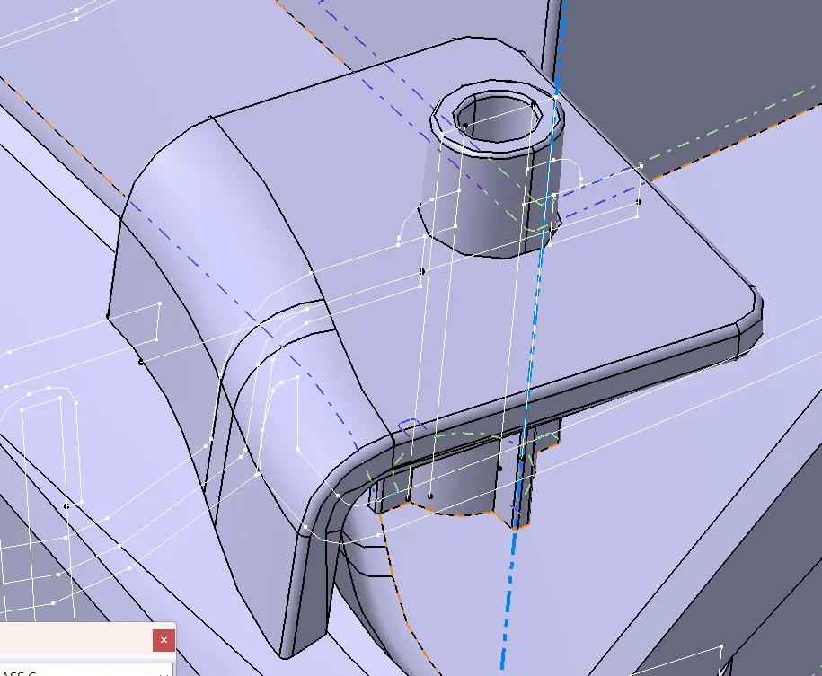
Fig 57. Flange design after draft, thickening and filleting.
Feature draft analysis is conducted for the flanges and the design clears the draft.
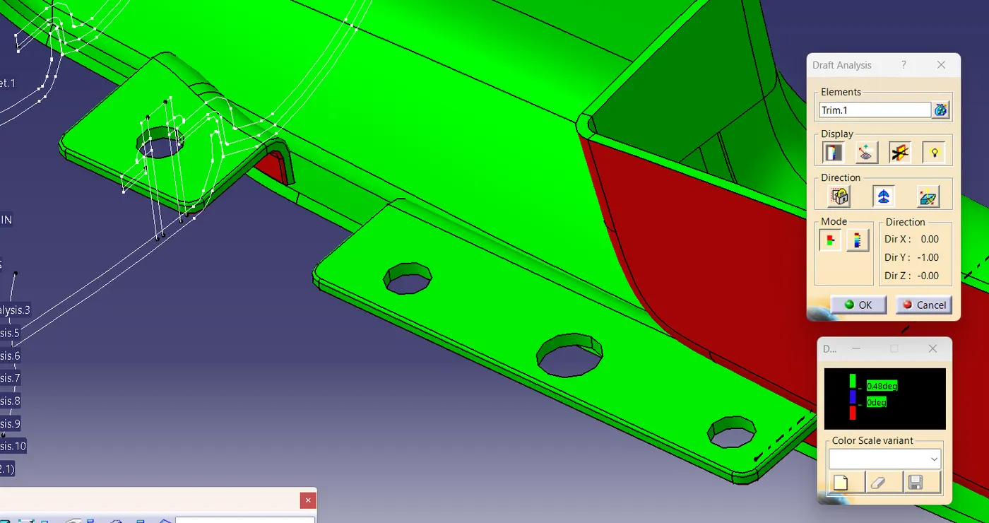
Fig 58. Draft analysis.
A similar method is adopted for the creation of other flanges also at the respective locations.
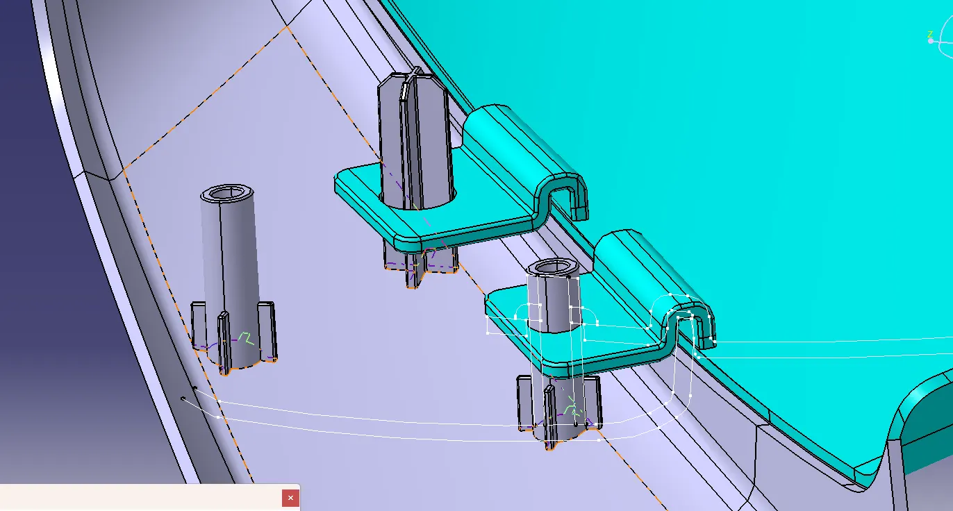
Fig 59. Flanges on Map pocket.
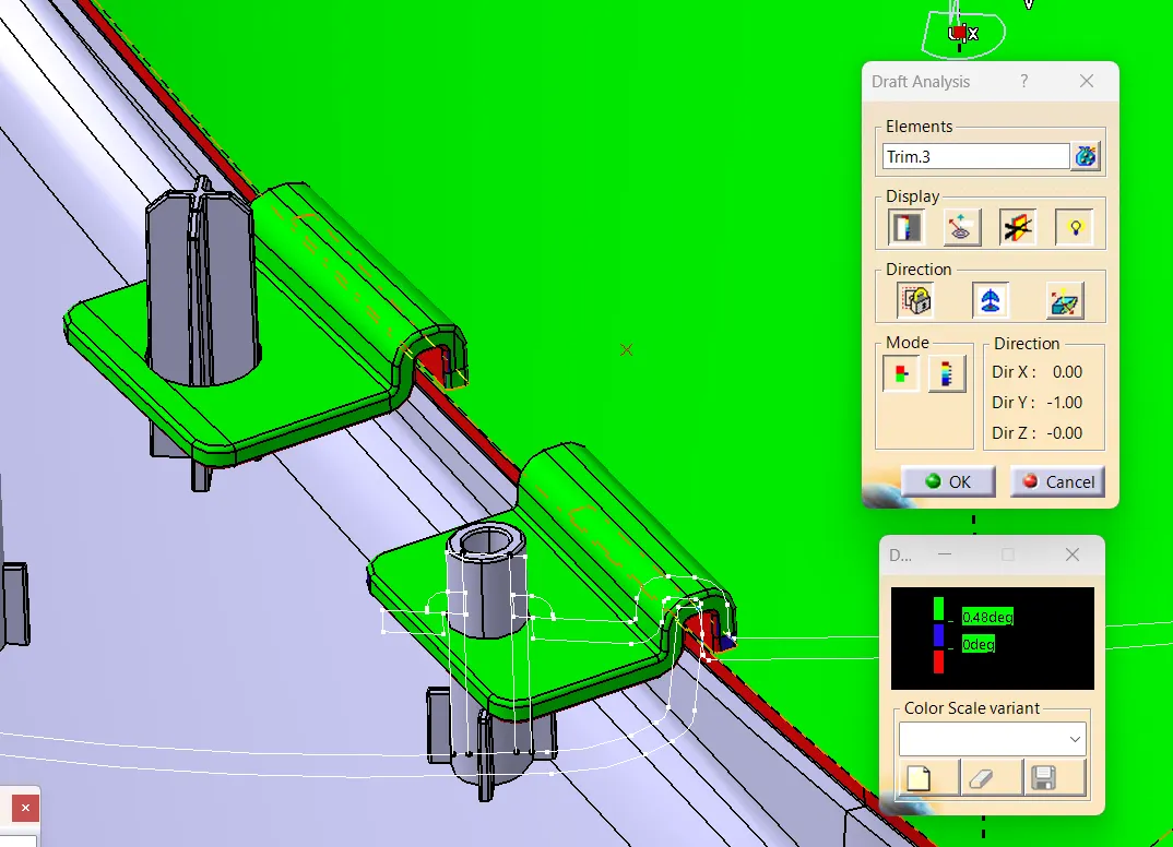
Fig 60. Draft analysis on Map pocket flanges.
Flanges on bottle holder were created in a different method. Here sketching, extruding and thickening is done for the flanges. Then the flanges are merged to the part body using boolean operator Union Trim.
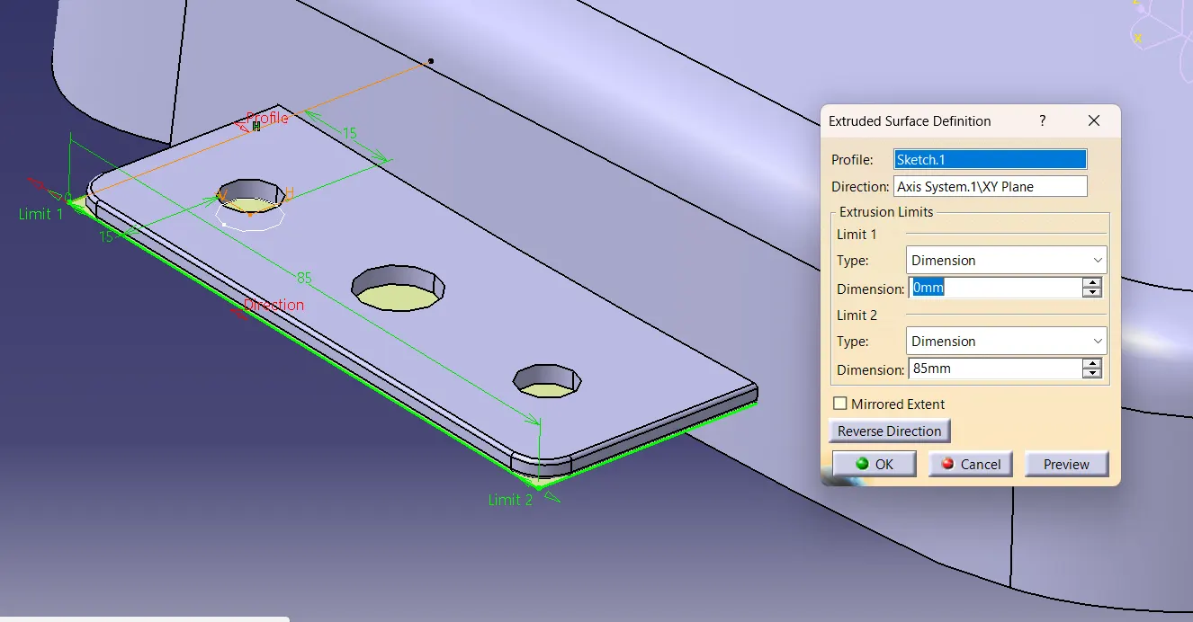
Fig 61. Extruding of flange surface.
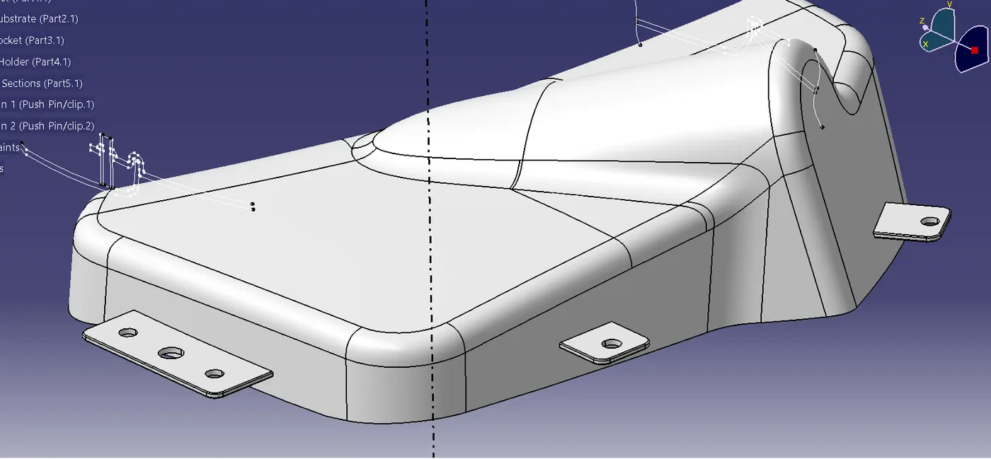
Fig 62. Bottle holder with flanges.
All the flanges were given a draft of 0.5º and they cleared the draft analysis.
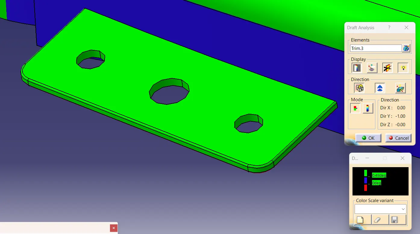
Fig 63. Draft analysis on flanges.
Assembling push pins with dog house
Push clips are used as an attachment feature for holding two panels together. In cars, they are used for trim panels, door trim, fenders, bumpers, engine covers etc. Here they are mounted on the dog house.
They are attached to the dog house by giving Coincidence and Contact constraints.
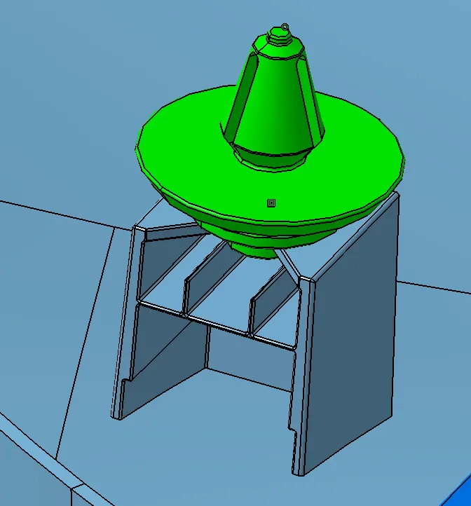
Fig 64. Push pin and Dog house assembly.
The following constraints were given for the final assembly.
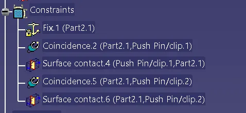
Fig 65. Constraints.
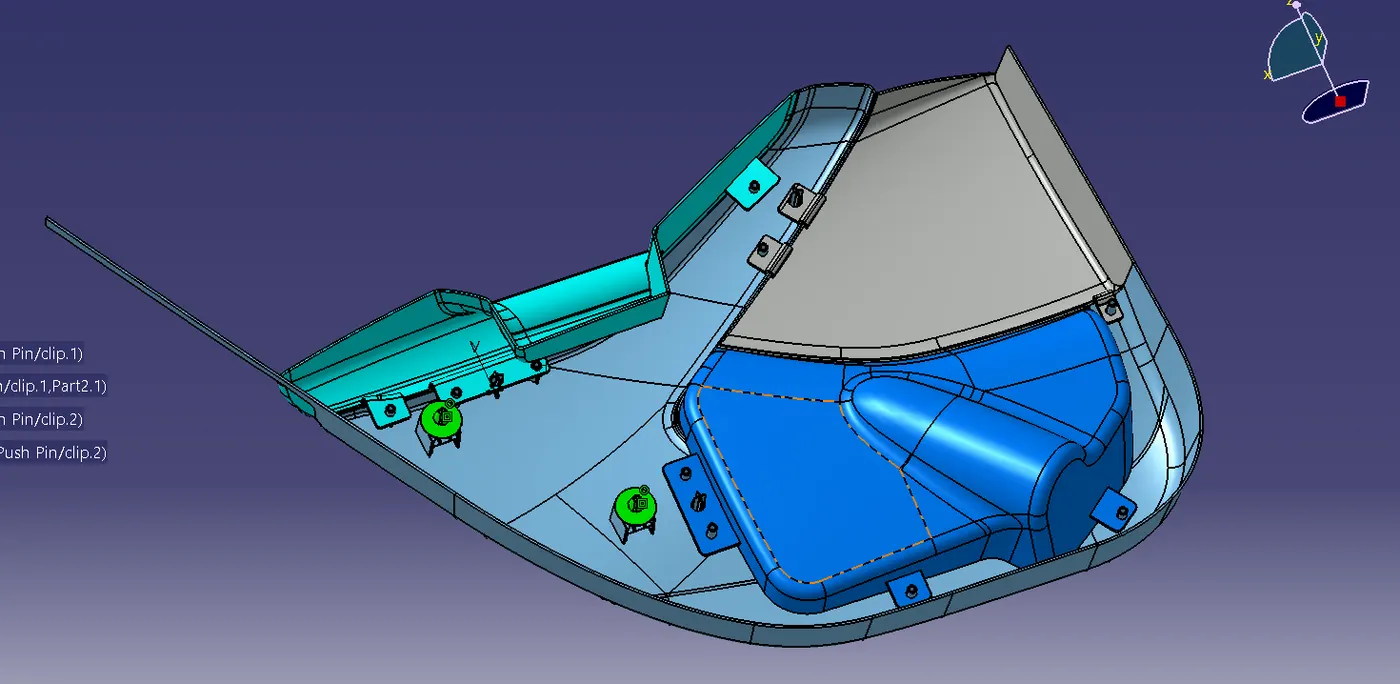
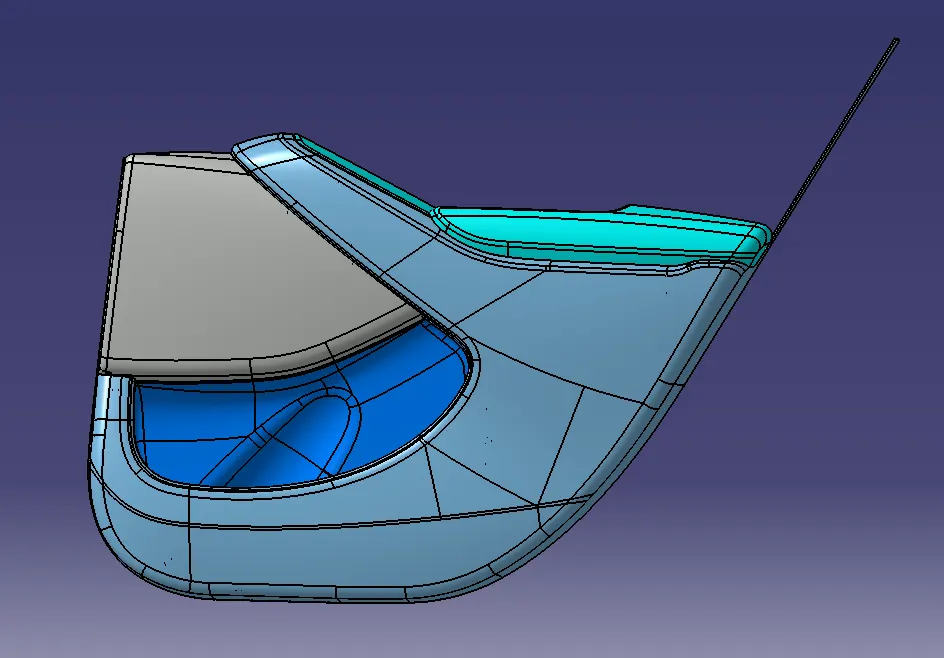
Fig 65 & 66. Door Trim Final Assembly.
Conclusion
From the given Class A surfaces and master sections, an assembly of the door trim is done. For each part, class B and class C surfaces were created, trimmed and converted to solid bodies and draft analysis were performed. Then attachment features were created. Heat stakes, locators and dog house with push pin on the main substrate and flanges on the remaining parts to facilitate proper mating. Draft analysis for the attachments were also done. By giving the required constraints, the final assembly was completed.