Week 9 - Challenge 2 - Switch Bezel Design
SWITCH BEZEL DESIGN CHALLENGE
In this challenge, a switch bezel is designed using the given class A surface and a draft analysis is also done for the design.
Switch bezels in car are parts which contains switches and controls for different functions like window control, door lock/unlock, media controls etc.
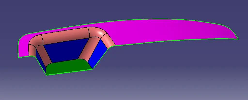
Fig 1. Class A Surface.
Design considerations
- Class A Surface should be aesthetically smooth and good.
- Class B Surface should have all supporting features like ribs.
- Parting line should coincide with the B surface since flashing couldn't affect the aesthetics of Class A.
- Class C Surface should also pass the draft analysis.
Draft analysis of Class A Surface
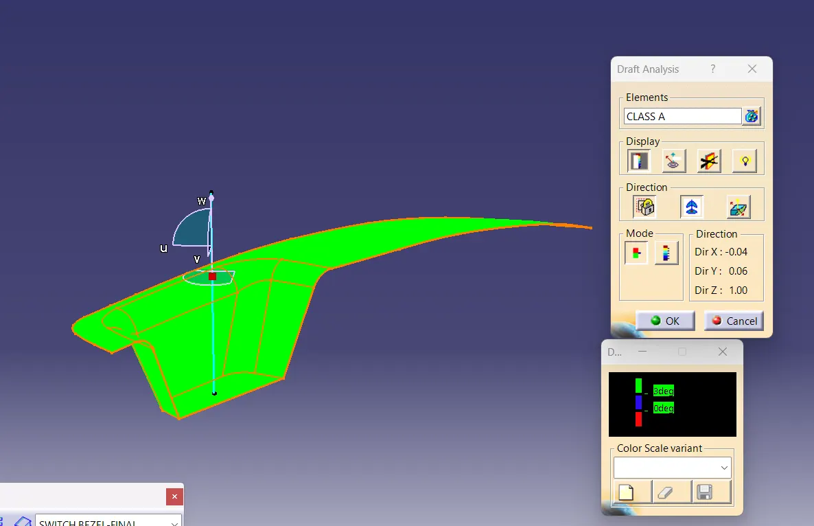
Fig 2. Draft Analysis of Class A.
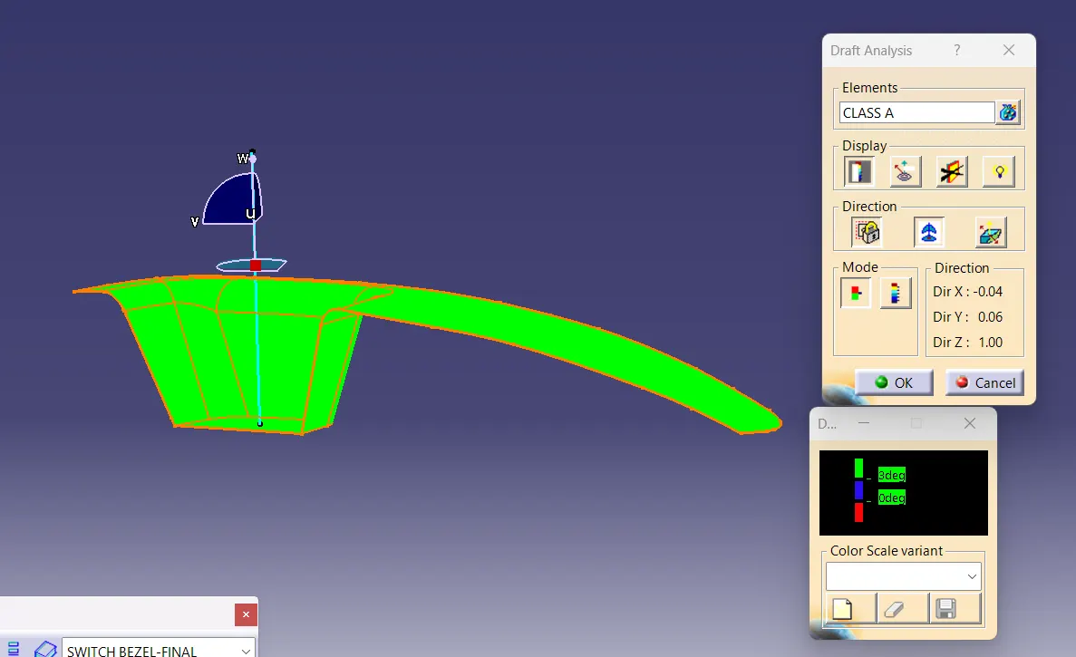
Fig 3. Draft Analysis of Class A
Creation of Tooling direction
First, the given Class A surface is checked for any gaps or irregularities. If there are some irregularities with the surface, it must be cleared using Trim, Split, Extrapolate and Join commands. The given Class A has no irregulaities as seen in Fig.1, so there is no need for any correction.
- Bisecting method is used to create the tooling axis.
- The base of Class A is extracted and a point is given at the centre of the surface, and an axis system is given there.
- Then using Intersect 3D elements command, the intersection along YZ plane is taken and from the projection, two lines are drawn along the walls and their bisecting line is taken. This is the line for Y direction.
- Similarly, a line along X axis is also needed. The projection is taken along XZ plane and a line is drawn along the wall.
- Here, since there is only one wall, we draw a line which is considered temporary by taking an angle of 6 degrees (this angle is taken because, visually it appears almost perpendicular to the base) from the drawn line along wall. This is the line for X direction.
- Then the bisecting line of the two considered line is drawn and it is taken and published as the Tooling Axis.
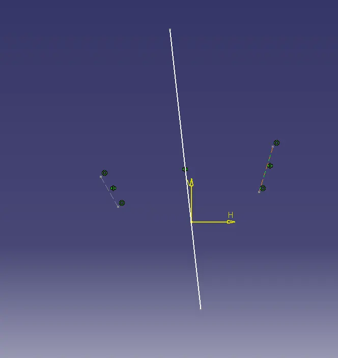
Fig 4. Line 1 for tooling direction (for Y diretion)
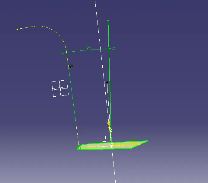
Fig 5. Line 2 for tooling direction (for X direction)
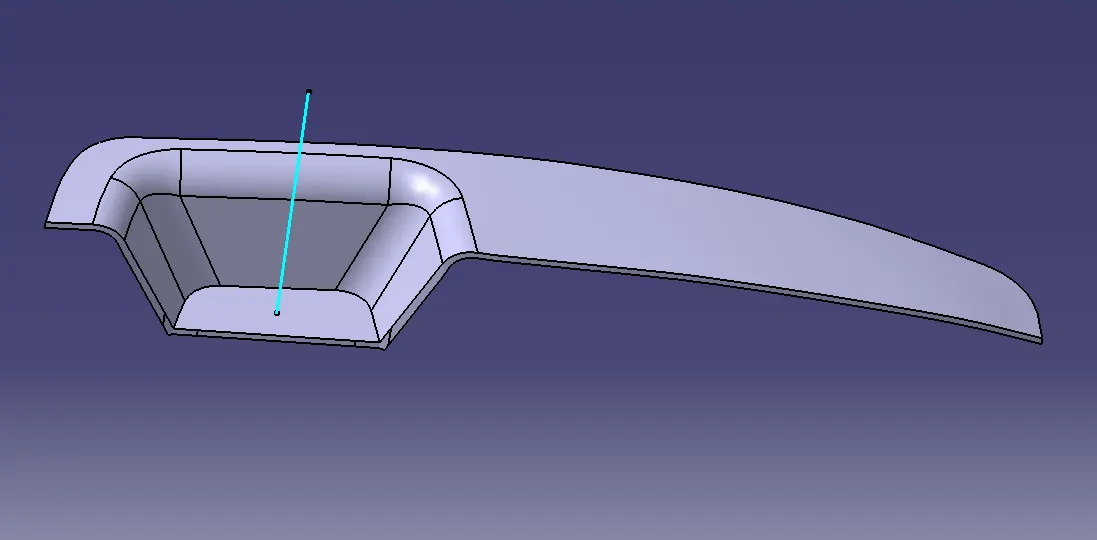
Fig 6. Tooling Axis.
Creation of Class B Surface
- For creation of Class B Surface, the surfaces of the part except the filleted areas are extracted one by one and untrimmed.
- All the surfaces are extrapolated in order to get them intersected.
- Each surfaces (walls, rest surface and base) are offseted to the thickness of the part.
- The surfaces are trimmed between each other to get the Class B surface and fillets were given.
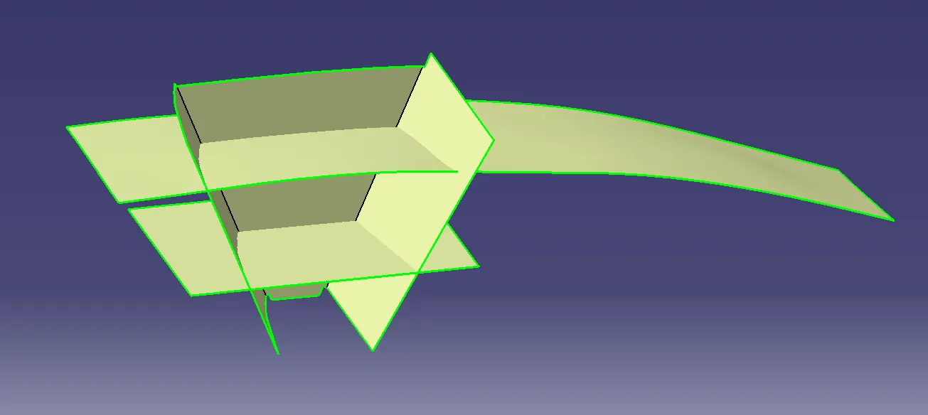
Fig 7. Surfaces of Class B before trim.
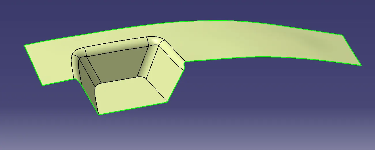
Fig 8. Class B Surface - final.
Creation of Class C Surface
- The outer edges of Class A are extracted.
- In order to avoid patches, the curve is smoothened using smooth curve command.
- The Class C surface is created from the curve using sweep command and the draft angle is given as 3°.
- The gaps within the Class C surface is closed by extapolating and trimming the surfaces.
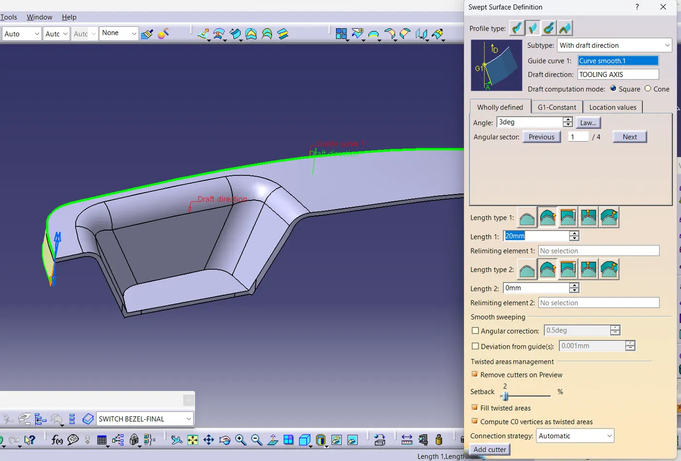
Fig 9. Sweep operation of 1st surface.
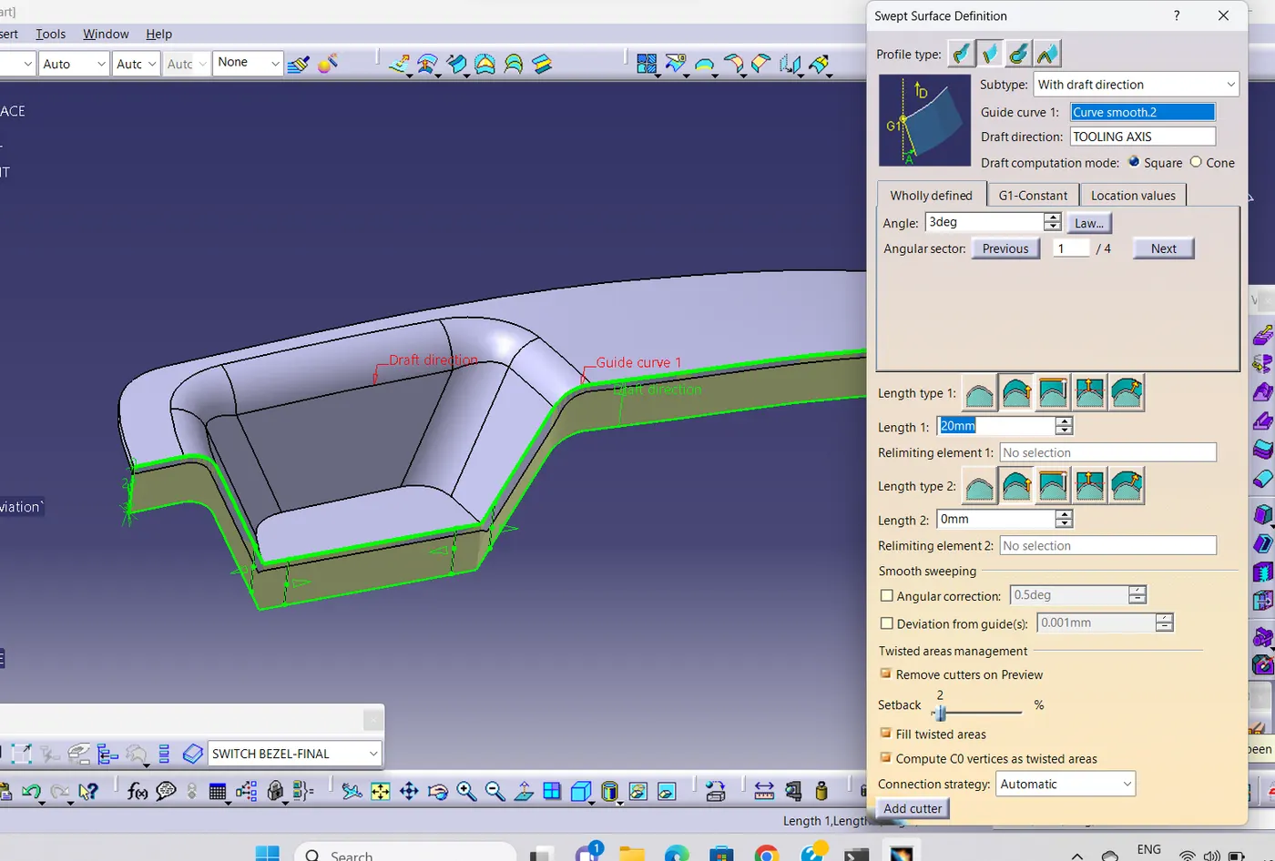
Fig 10. Sweep operation of 2nd surface.
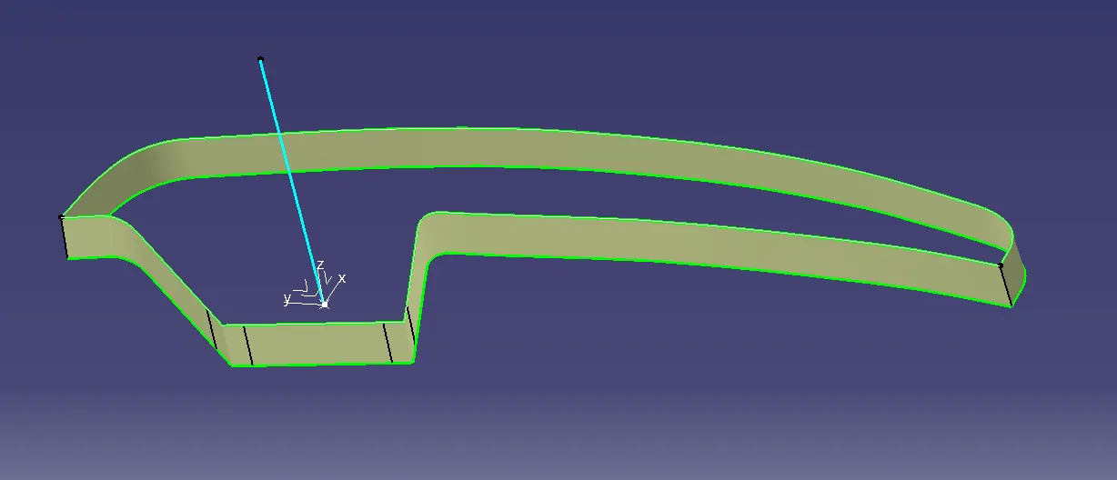
Fig 11. Class C Surface.
After creation of Class C surface, it is joined with the Class A surface using join command. If there are any gaps appearing due to the smooth curve operation, it can be solved by extrapolate and trim operations. It is then joined and trimmed with Class B.
The part is then made to a closed body using Close Surface command in part workbench.
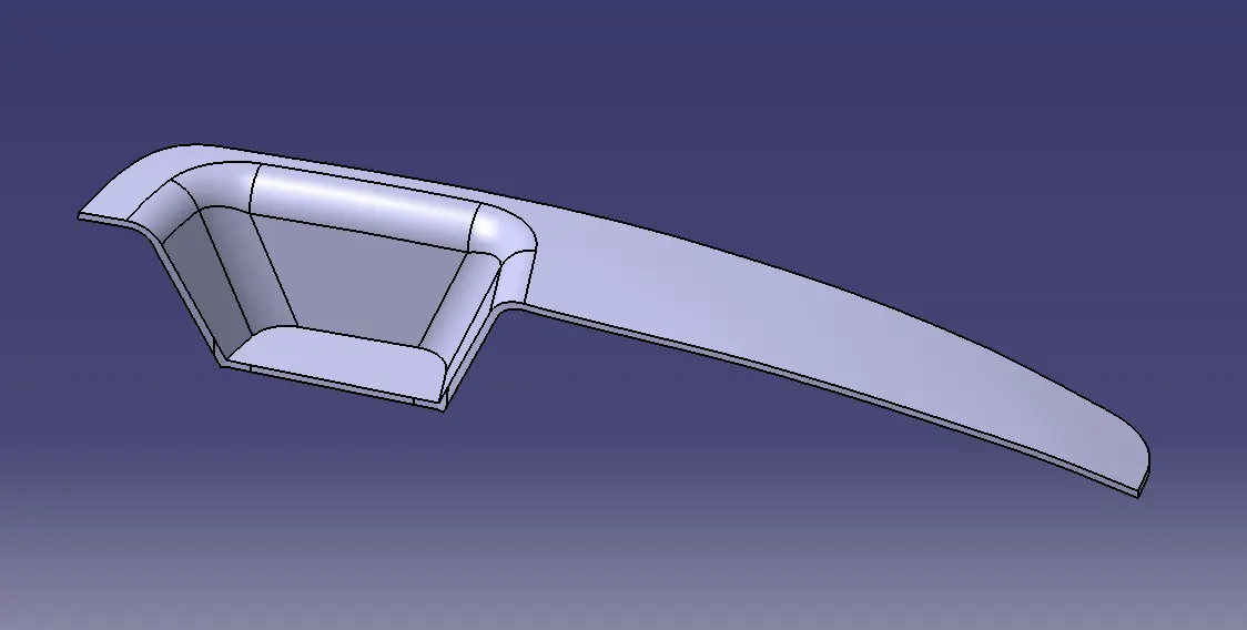
Fig 12. Part after Close Surface operation.
Draft Analysis
- First change the view mode to custom view parameters and select material mode from the list.
- Select feature draft analysis command.
- Click the axis icon and place the axis aligned with the tooling line.
- After aligning the axis click on the lock icon and click on the part.
- Green colour shows the part satisfies the 3° draft angle and is clearing the draft analysis.
- If the part fails to clear the analysis use the analyses under running point tool to check the angle at the respective region and make proper corrections.
- Here in this design, the part completely satisfies the draft analysis.
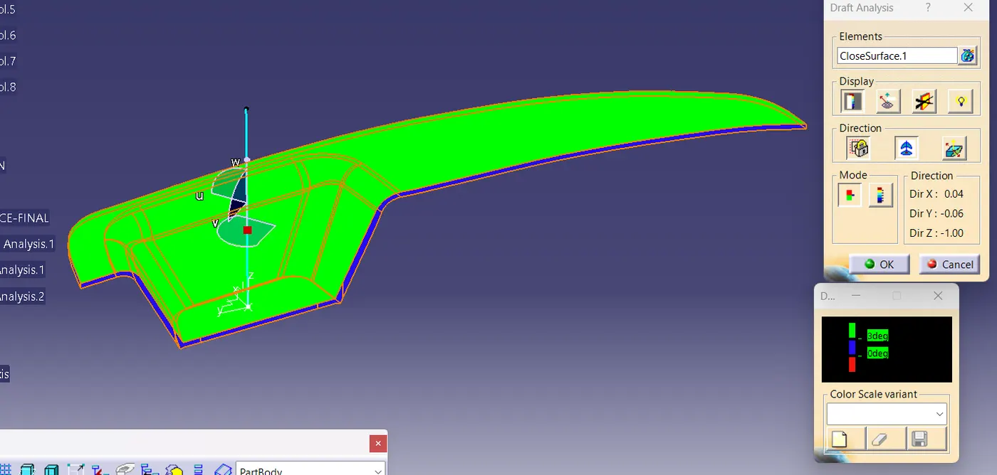
Fig 13. Draft analysis of final design.
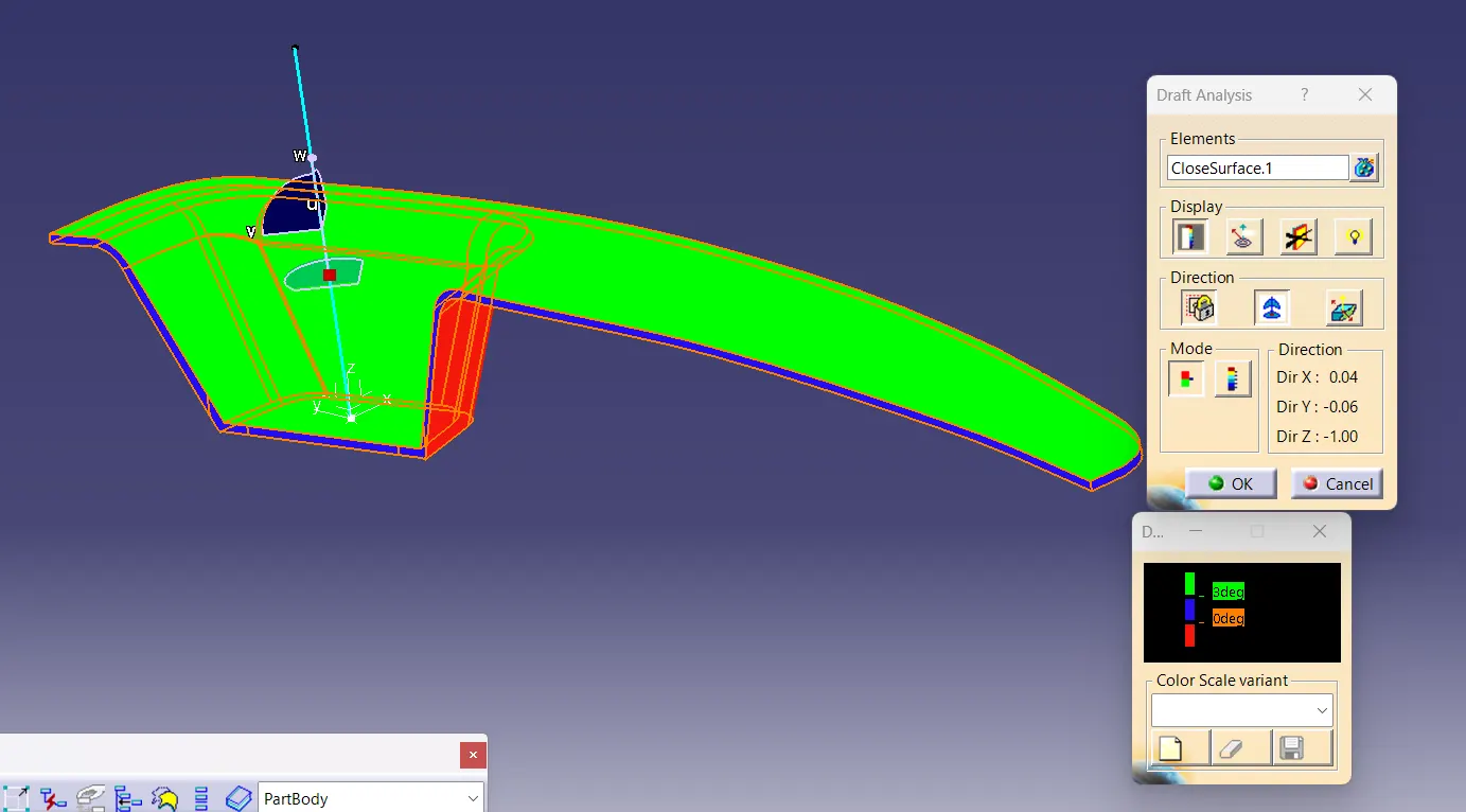
Fig 14. Draft analysis of final design.
Feature Tree Screenshots
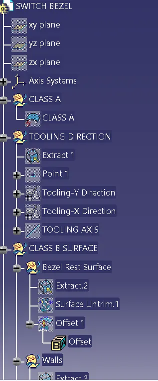
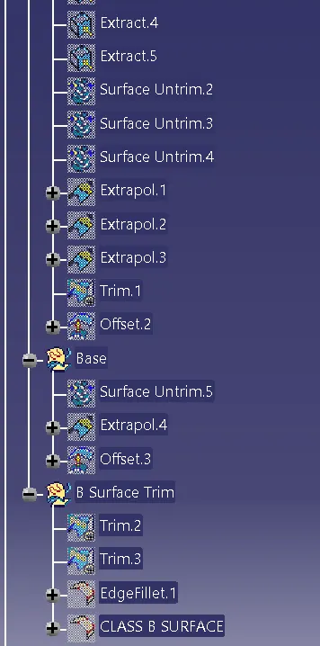
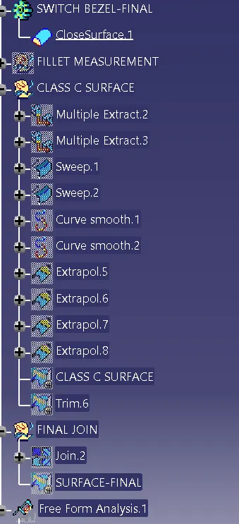
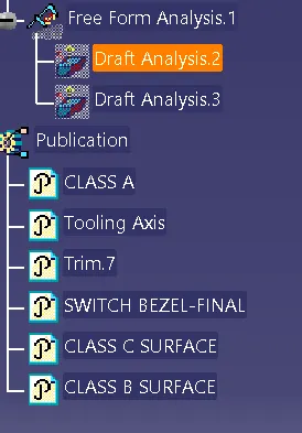
Fig 15. Feature Tree.
Thank You.