Week 10 - Challenge 2- Attachment Feature Creation (Dog House)
ATTACHMENT FEATURE CREATION - DOG HOUSE
In this exercise, a portion of door trim is designed using the given Class A surface and Dog House is designed for the door trim, considering the design requirements.
Dog House
Dog House is a feature used in plastics that helps to avoid sink marks. This is the primary function of a dog house.
Along with that, if we need an attachment feature, for instance, a screw boss at a distance 100mm away from B surface, creating a 100mm srew boss is not feasible. So we create a dog house on the B surface and attach the screw boss on the dog house.
The third application of dog house comes in situations like, if we need a screw boss perpendicular to the tooling direction. At such instances, we design a dog house and attach the screw boss on it.
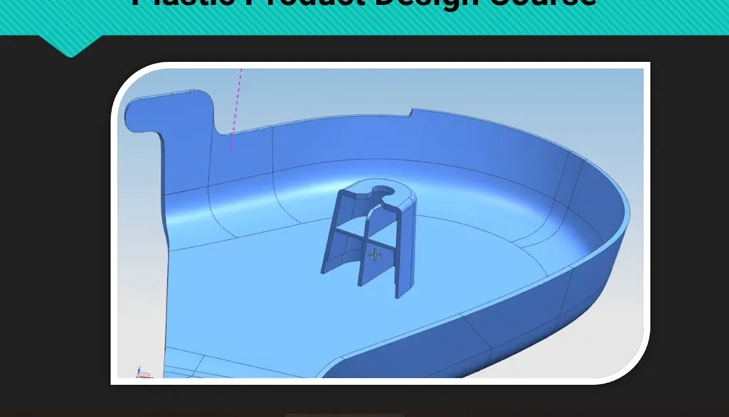
Fig 1. Dog House.
Design of door trim
The given Class A suface is checked for gaps or irregularities using boundary or join command. Here no such issues were present and the given surface was fine.
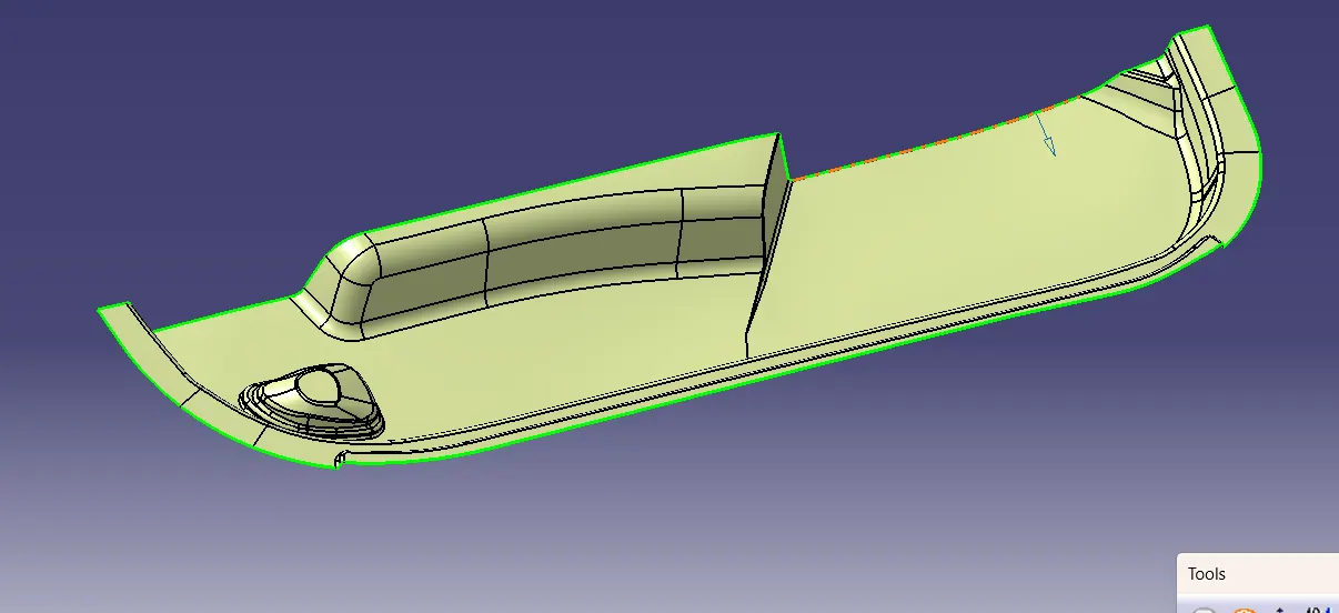
Fig 2. Class A surface.
Tooling Axis Creation
- The Class A surface is examined and found that almost all the faces can be cleared if tooling is given along Y direction.
- Bisecting method is adopted for the creation of tooling axis.
- An extract of the flat portion of the base is taken.
- A point is created at the centre of the extract and an axis system is created at that point.
- An intersection is taken between the YZ plane and the Class A surface.
- Two lines are constructed tangent to the side walls and a bisecting line is taken as the tooling axis (temporarily).
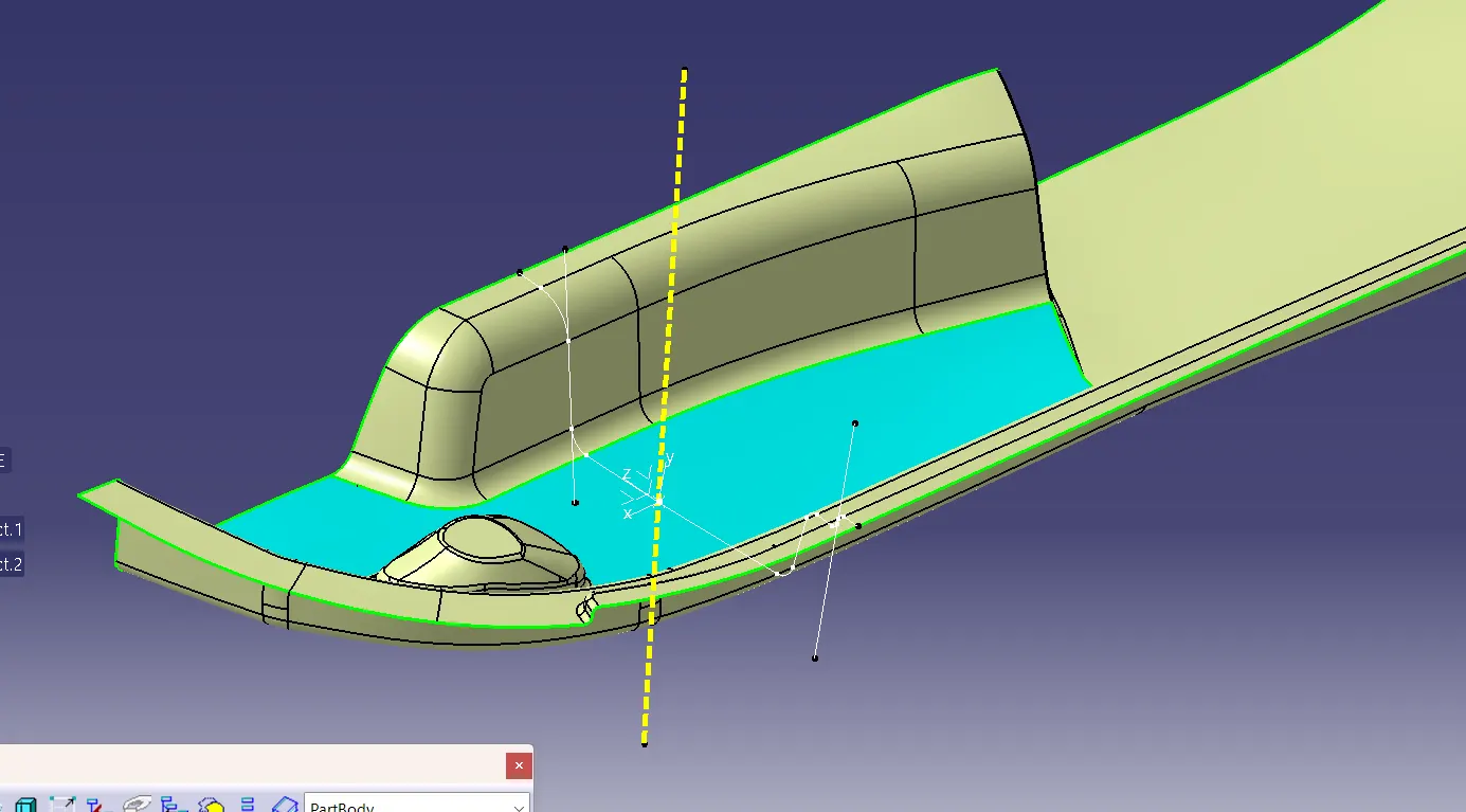
Fig 3. Tooling Axis.
Draft analysis on Class A surface
Draft analysis is done on the Class A surface to confirm whether the considered tooling axis clears the surfaces or not.
Steps:
- In the material view mode, select customize view parameters and select material option.
- Select feature draft analysis command.
- Select the compass icon, drag the compass and place it along the Tooling Axis.
- Select the Class A surface and check whether it clears the draft.
- Here the surfaces cleared the draft and the tooling axis line can be confirmed for further use.
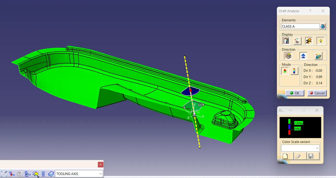
Fig 4. Draft Analysis of Class A surface.
Creation of Class B surface
The Class A surface is offseted by 2.5mm inwards to create Class B surface. While observing the new offseted surface, few portions were missing.
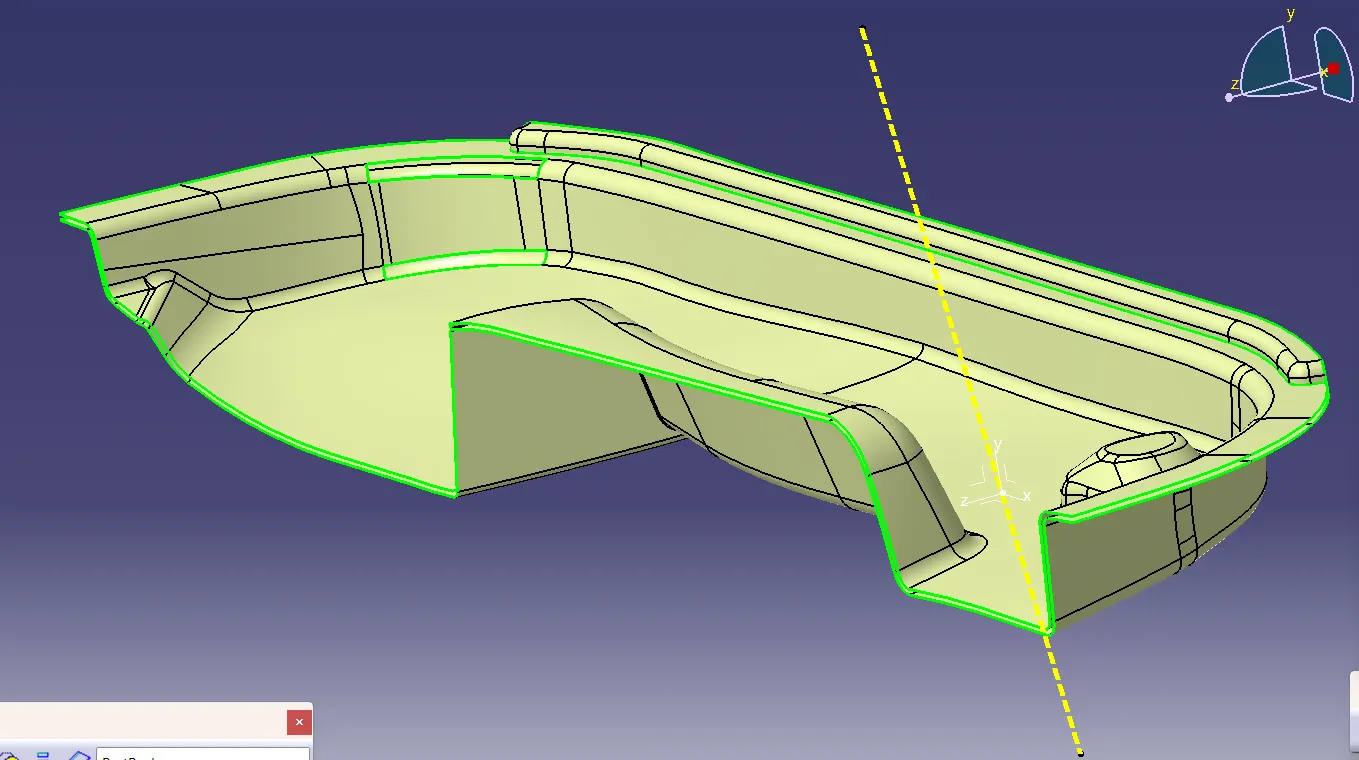
Fig 5. Class A is offseted and few portions were missing on the offset.
The missing portions were joined using multiple extract, boundary, join, multi section surface, extrapolate and trim commands and fillets were also provided using edge fillet command.
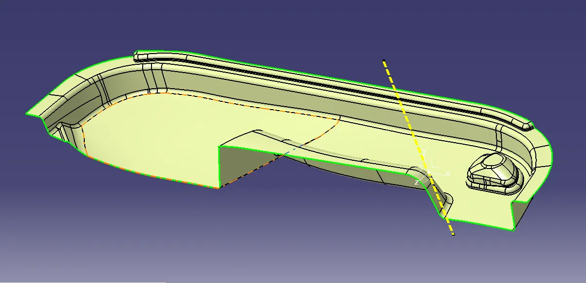
Fig 6. Class B surface after corrections.
Creation of Class C surface
The class C surface is created using sweep command from Class A surface boundary, and the draft angle with respect to the tooling axis is taken as 3º for edges which are perpendicular to the tooling axis and 90° with respect to the surface for edges that are parallel to the tooling axis. The boundary cannot be taken at a single stretch. It is taken as multiple boundaries and sweeps are given at each individual region. In order to connect between these individual boundaries, we use spline, boundary and multi section surface commands. Then after giving required extrapolations and trims, Class C surface is created.
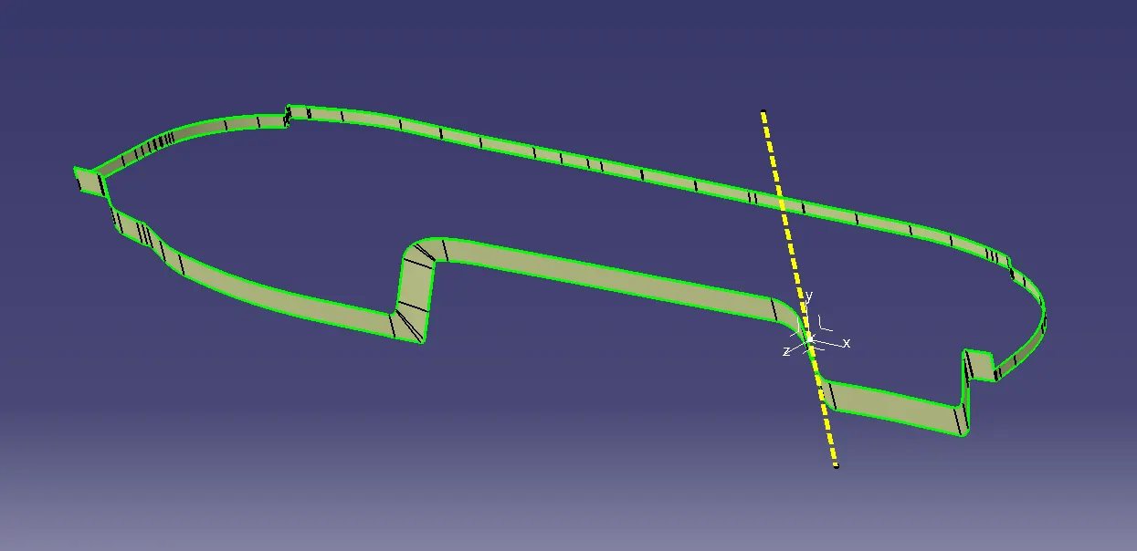
Fig 7. Class C surface.
Final Trim
First, Class C is joined using trim operation with Class A after extrapolation of the surfaces. Then the new surface is trimmed with Class B to create the the final trim part.
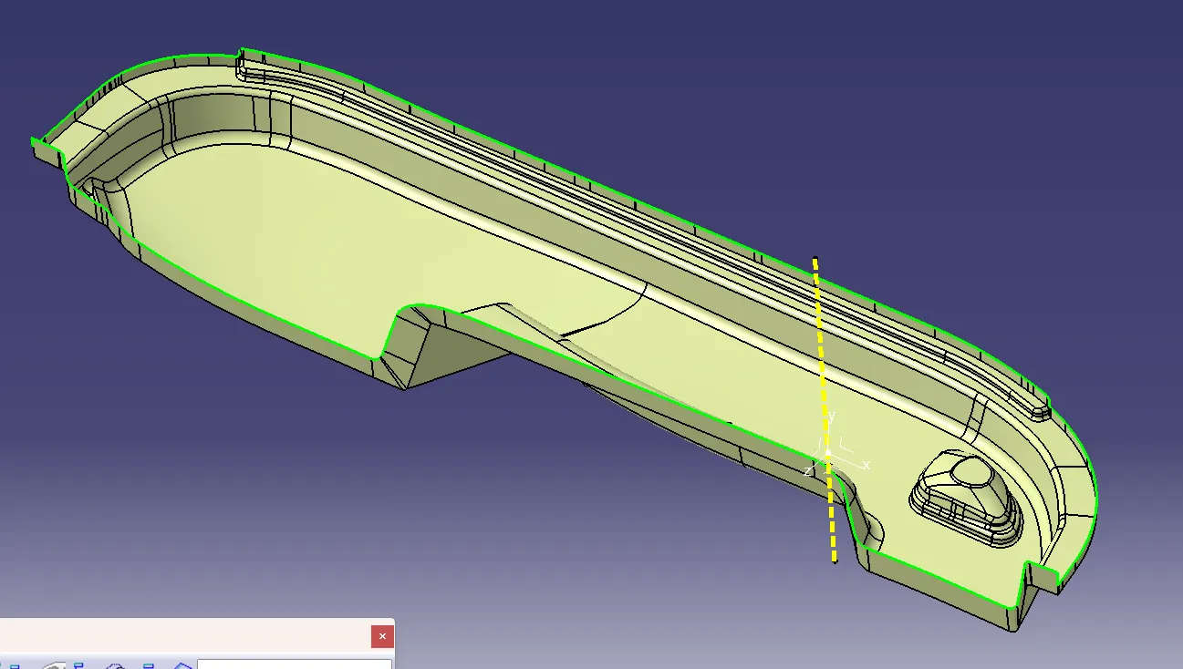
Fig 8. Class A joined with Class C.
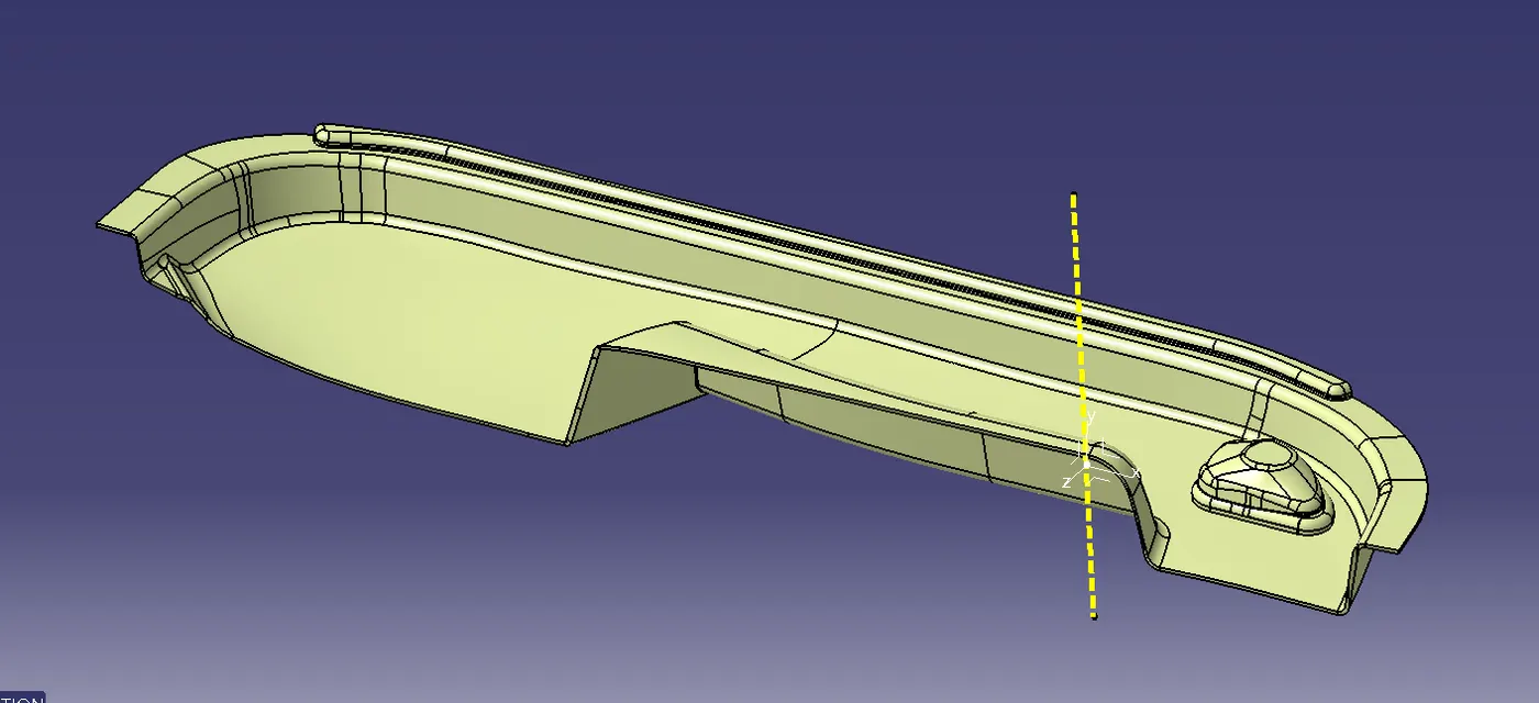
Fig 9. Final Trim.
Draft analysis on Final Trim
A draft analysis is conducted on the door trim before the creation of the dog house by following the same methods adopted for draft analysis of Class A and found that the surface is clearing the draft.
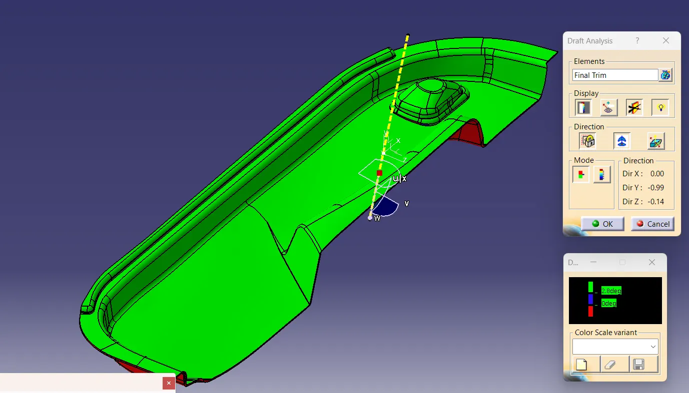
Fig 10. Draft analysis on Door trim.
The surface part is created into a closed body using Close Surface command in part workbench.
Dog House Creation
Dog house is created on the door trim, considering the requirements for dog house design.
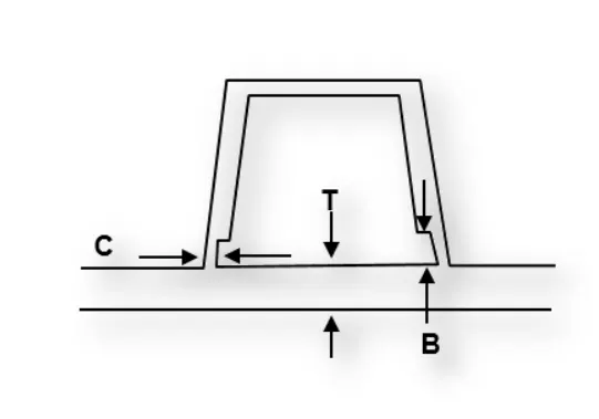
Fig 11. Dog house-parameters
Design requirements:
- Dog house thickness at intersection of part wall (C) should be 40% or less than the main wall thickness (T).
- Height B should be between 3-6mm.
- Width of dog house should be minimum 12mm.
- Minimum height of dog house should be 6mm. Less than 6mm causes weak steel condition.
- Minimum draft for dog house is 1.5° to the die draw.
Design methodology
- The base surface of the door tim is extracted, a point and plane is given at the place where we want to create dog house.
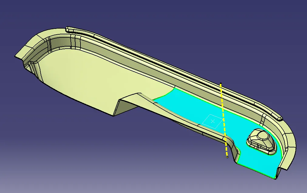
Fig 12. Extract, point and plane for dog house.
- The sketch for the dog house is done on the plane created and using the point as projection point.
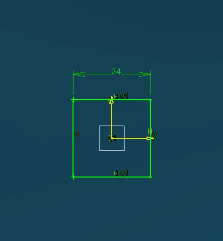
Fig 13. Sketch for dog house.
- The sketch is then padded for a height 20mm, taking the tooling axis as reference for the pad.
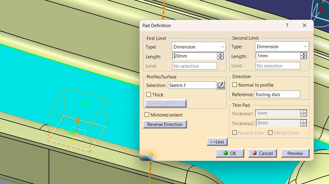
Fig 14. Padding operation.
- Using shell command, the pad is made to a hollow and the thickness of 2mm is given for the shell.
- A draft of 1.5º is given to the outer faces using draft command. Here the tooling axis, which created first is the pulling direction.
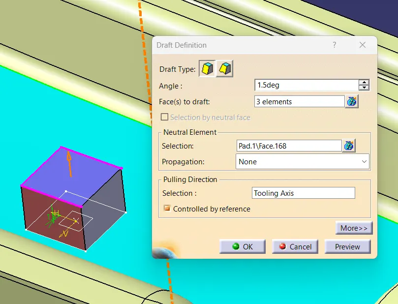
Fig 15. Drafting operation - outer faces.
- The inner face of the dog house will not clear through the tooling axis which was created initially.
- So we create a side core along X direction, facing the inner faces of the dog house.
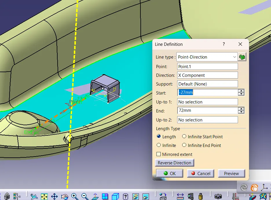
Fig 16. Side core creation.
- Then draft of 1.5º is given for the inner walls of the dog house, taking the side core as the pulling direction.
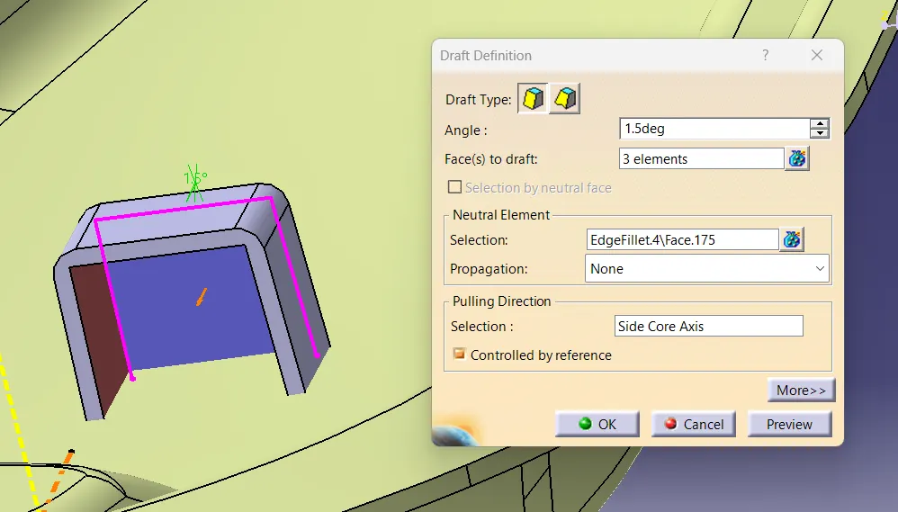
Fig 17. Draft for inner walls.
- For creating the C portion of the dog house, where it connects with the base surface, the inner walls of the dog house is extracted and offseted by 0.4xbase thickness ie, 0.4x2.5=1mm.
- The B height is taken as 4.5mm. So a line is plotted at a plane of this distance and extruded.
- It is then trimmed with the offset surface to create the base deviation surface
- The trim surface is split with the dog house body to cut the base to create C portion.
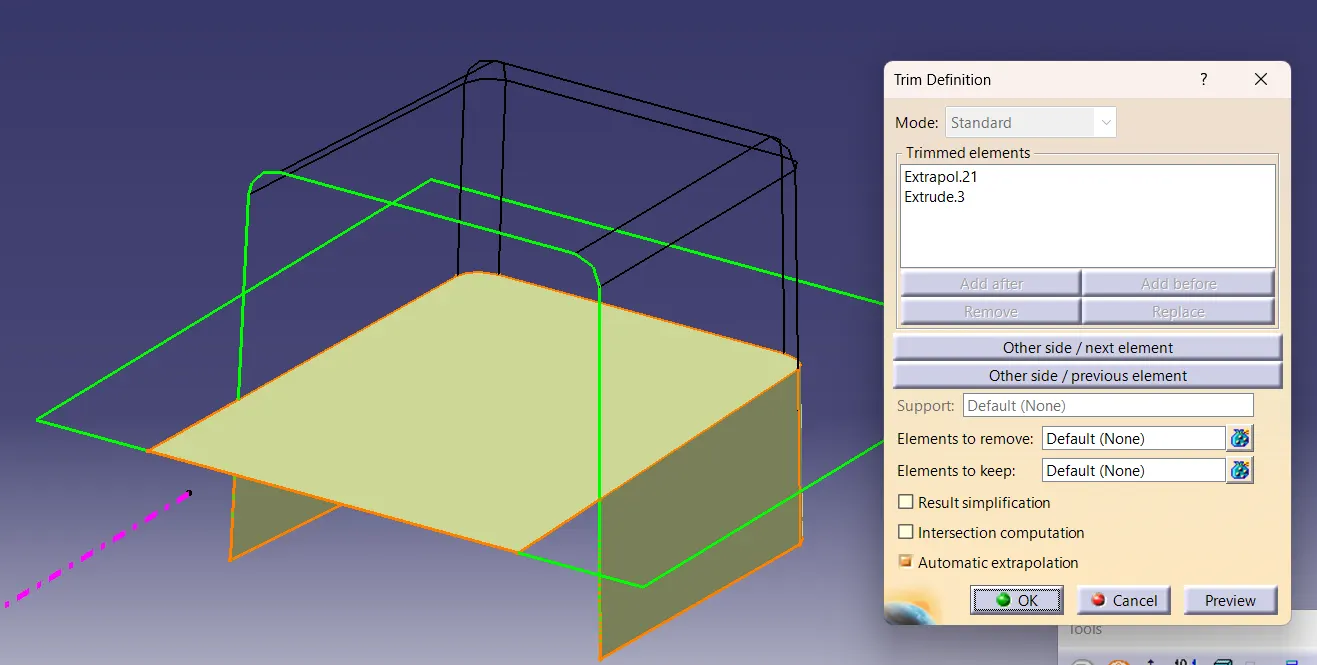
Fig 18. Trim operation for base.
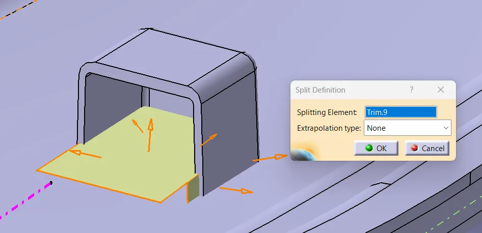
Fig 19. Split operation for creating base portion.
- The top portion of the cut surface needs drafting and it is done on the surface, considering the side core as the pulling direction.
- Fillets of 3mm are given at the outer wall edges and inner wall edges were given 1mm thickness and a thickness of 0.5mm is given at the top edges of C part.
- The final dog house is now added to the main part body using add in boolean operation.
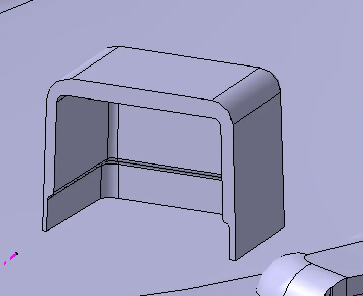
Fig 20. Dog house - final design.
Draft analysis of dog house
A draft analysis of both outer walls and inner walls pf the dog house is done using feature draft analysis command in surface workbench.
Steps for draft analysis:
- In the material view mode, select customize view parameters and select material option.
- Select feature draft analysis command.
- Select the compass icon, drag the compass and place it along the Tooling Axis.
- Select the outer wall of dog house and check whether it clears the draft.
- For inner wall, the compass icon should be placed on the side core axis.
- Select the inner wall of the dog house and check whether it clears the draft.
- Here both inner and outer surfaces cleared the draft.
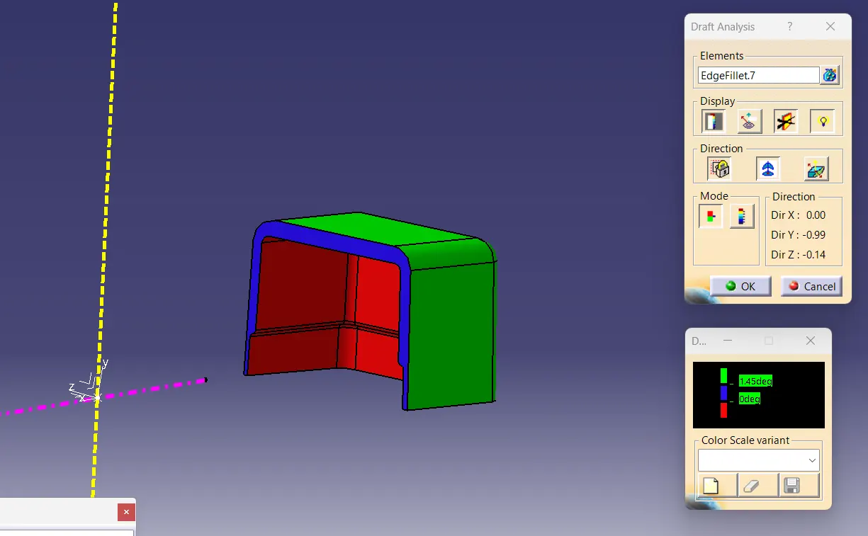
Fig 21. Draft analysis for dog house outer wall.
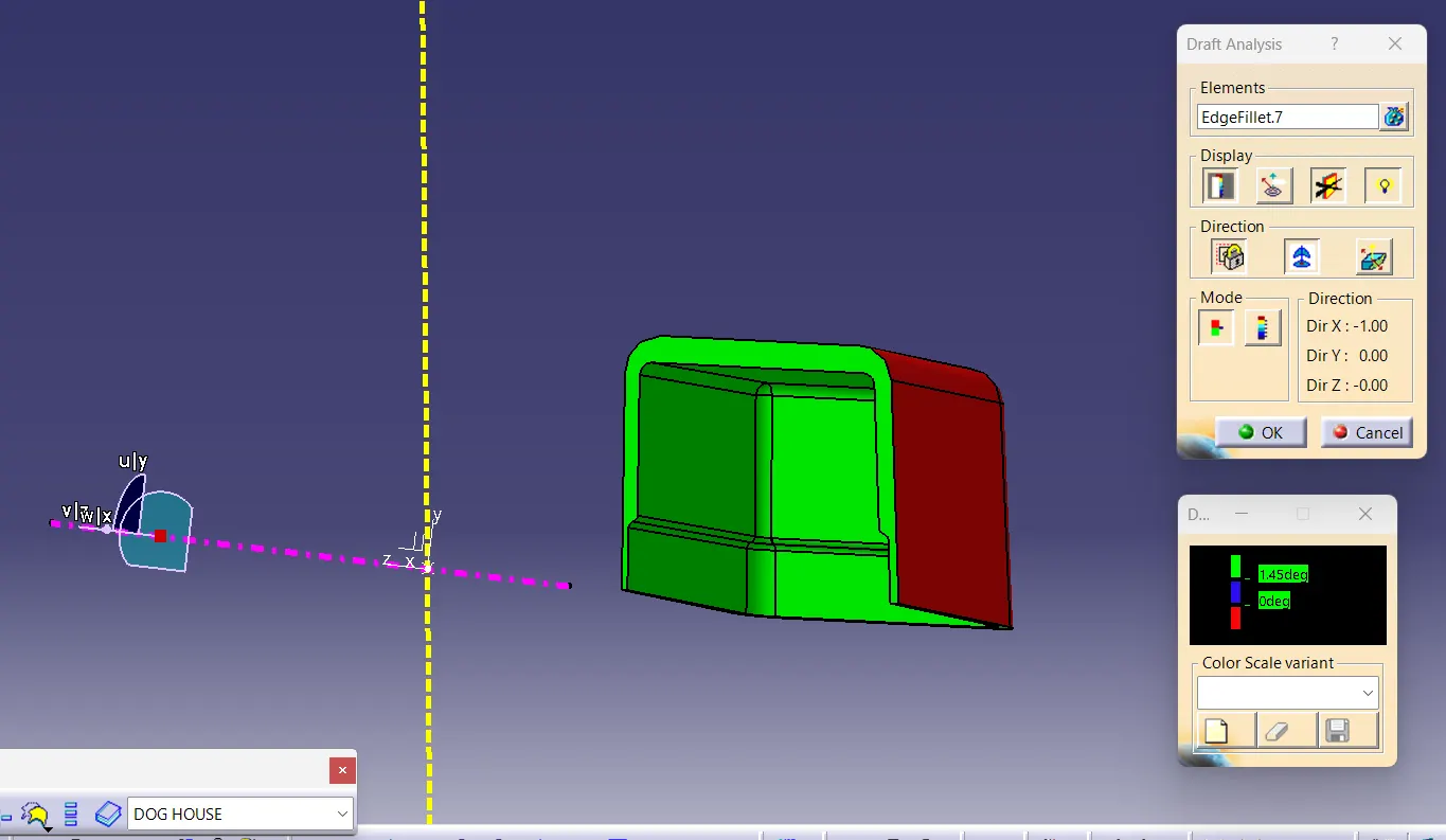
Fig 22. Draft analysis for inner wall of dog house.
One more dog house is created by following the same steps and dimensions of he 1st design.
Final design
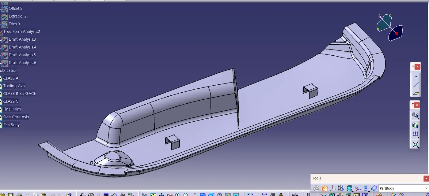
Fig 23. Final design.
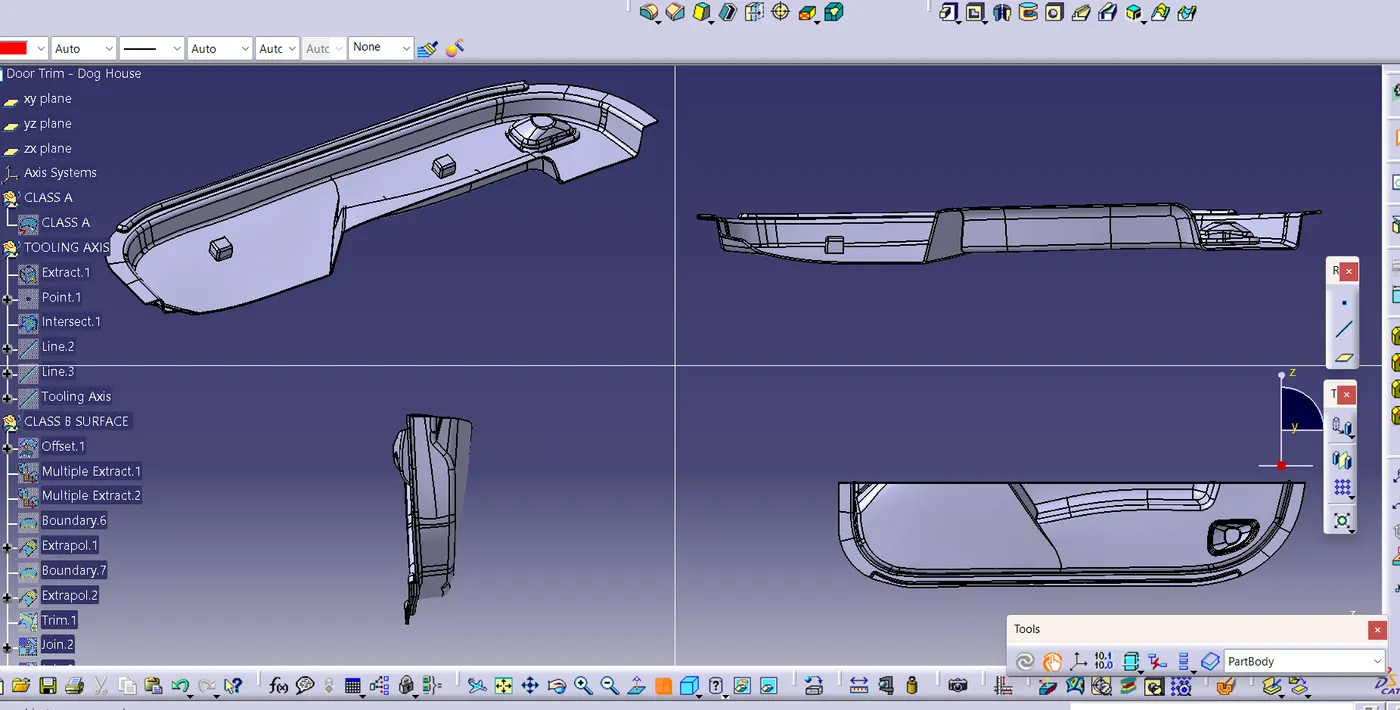
Fig 24. Final design - different views.
Thank you.