Roof Design
Roof Design
Introduction
An automobile roof or car top is the portion of an automobile that sits above the passenger compartment, protecting the vehicle occupants from sun, wind, rain, and other external elements. As seen from outside, it is not just a single panel with a specified thickness. It has got reinforcements inside in the form of front roof rail, rear roof rail, bow roofs and centre roof which provides the required strength to the panel.
The surface of the roof is manufactured as curved surface instead of being flat because, curved surfaces can provide more strength when compared to flat ones. The number of bow roofs and the centre roof rail depends on the size of the car. There are even cars which has got only a front roof rail and rear roof rail without bow roofs and centre roof rail.
In this project, I create a Roof Assembly in NX CAD by using the given styling and master sketches, by developing essential flanges for the outer roof and creating reinforcements. Along with that, draft analysis, curvature study and snow load calculations are also performed.
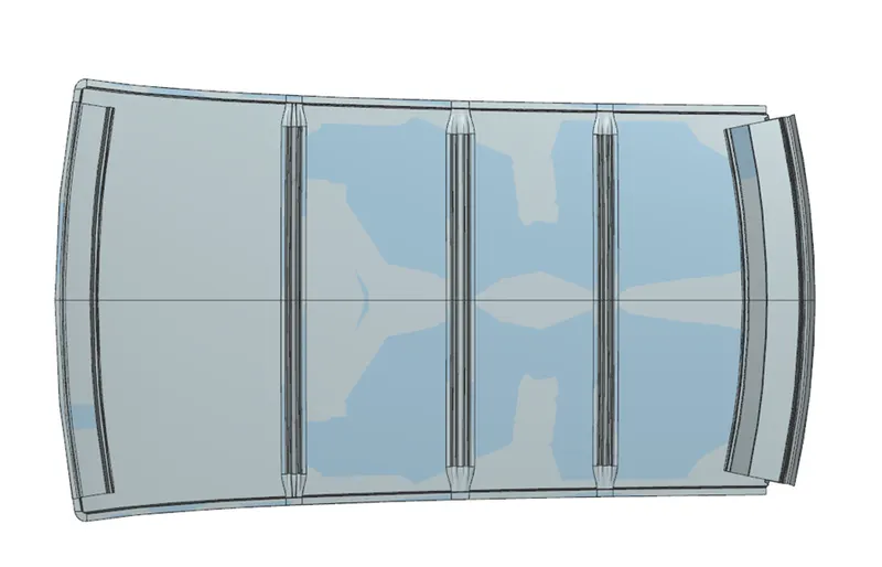
Fig 1. Roof assembly design.
Front Roof Rail
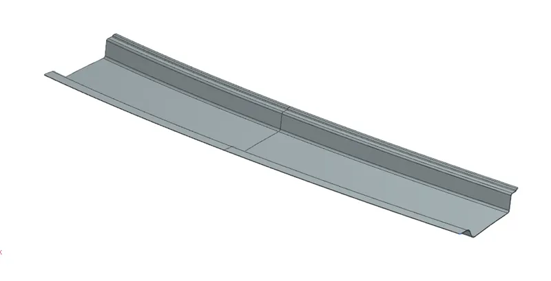
Fig 2. Front Roof Rail
Front roof rail is the part where the wind shield glass and the body side outer get fixed. It also acts as a reinforcement to provide the required strength.
The design of the front roof rail should be based on the visibility criteria and headroom clearance. According to the visibility criteria, the distance between the bottom panel of the front roof rail and roof outer panel is determined to be around 32 mm.
The length is determined to be around 80mm to provide proper head room for the passengers. Front section of front roof rail is spot welded to the front ditch area and other parts are fixed with help of mastic sealants.
Rear Roof Rail
Rear roof rail is the part where the back door and the body side outer get fixed. It is an important reinforcement of roof assembly.
The dimensions of rear roof rail are also in accordance with the headroom clearance requirement and the rear visibility criteria.
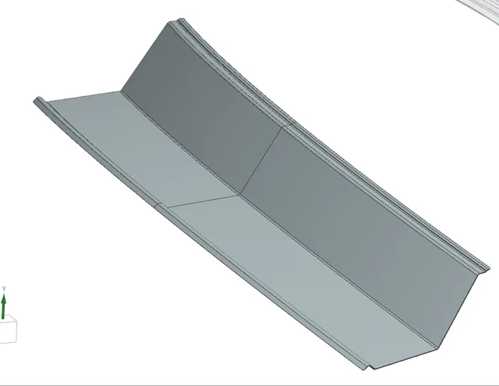
Fig 3. Rear roof rail
Bow Roof
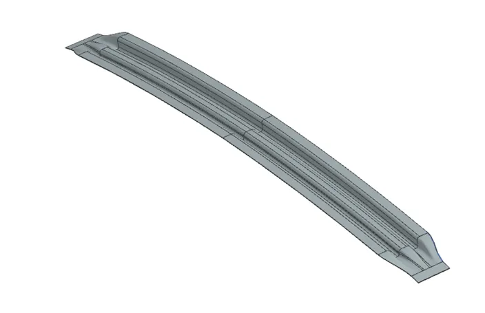
Fig 4. Bow Roof
Bow roofs are given to improve the strength and load bearing capacity of the roof. In this design 2 bow roofs are given at either side of the centre roof rail. They are joined to the outer panel by spot welding and mastic points.
Centre Roof Rail
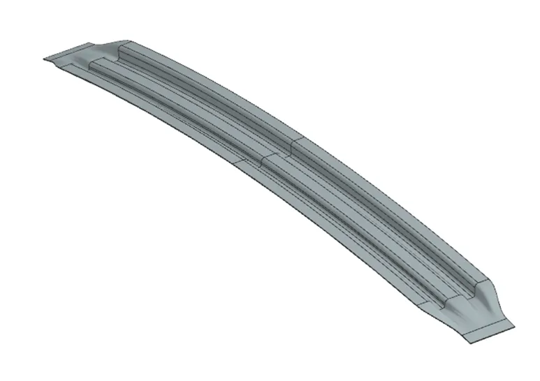
Fig 5. Centre roof rail
Centre roof rail effectively supports the flat area of the roof which is more susceptible to failure when compared to curved surfaces. Generally central roof rail is placed at the centre of the roof which is connected to the B-pillar support structure.
Joining Process
Mastics and spot welding are used to join the reinforcements to the roof outer panel.
Roof Crush Test
Roof crush test is one of the important tests to check whether the roof is suitable or not. This test is done based on the regulations of Institute for Highway Safety.
The ratings are given upon how fast the roof regains its original shape after deformation and how deep the protrusion is.
The roof is deformed by applying a load and there are certain parameters for applying the load. The load is applied in such a way that it is 5 degree is tilted from the front end to the rear end and the load will be in 1800 mm in length and 750 mm in width. The load is applied at the position of 25 degree from the flatness of the roof. The load is applied on the roof for almost 120 sec and the crush speed at which the load applied is 13 mm/sec or less than that.
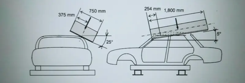
Fig 6. Roof crush test.
If the deformation goes above the required level, then the strength of the roof should be increased by providing embosses, more mastic points or thickness.
Curvature study
This is conducted to ascertain whether the positioning of the bow roofs is correct. For the prediction of bow roof positions, we use heat distortion formula.
W= [1.73 x 10^ (-3) x L] + [1.85 x 10^(-8)x(R^2)/t]+[1.10x10^(-3)x l] – 2.68
Where,
L = Roof Length in X-Direction[mm](Roof dimension in 0-Y)
R = Roof curvature
R = 2(Rx x Ry)/(Rx + Ry)
Rx = X curvature
Ry = Y curvature
t = Roof plate thickness [mm]
l = Bow Roof Span [mm]
Judgement condition OK if W<2.7
Calculations
To study the positioning of bow roof, all the required parameters are measured from the design and the calculation is done using the heat distortion formula.
L= 2029.24mm
t = 0.75mm
|
Section |
Rx |
Ry |
R |
l |
W |
OK/NG |
|
FRR-BR1 |
5692.27 |
3010.47 |
3938.16 |
516.56 |
1.78 |
OK |
|
BR1-CRR |
4721.95 |
7200.87 |
5703.71 |
393.56 |
2.06 |
OK |
|
CRR-BR2 |
3896.35 |
10993.81 |
5753.56 |
332.62 |
2.01 |
OK |
|
BR2-RRR |
3284.01 |
14556.35 |
5358.99 |
348.72 |
1.92 |
OK |
From the above table, it is evident that the positioning of bow roofs is appropriate, and the roof complies with the heat distortion criteria.
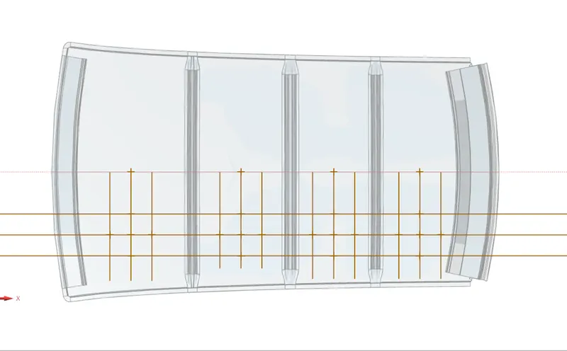
Figure 7. Sketching for finding the intersection points for calculating Rx and Ry.
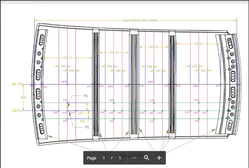
Figure 8. Parameters in Heat distortion calculation.
Snow Load Prediction
This test is performed to determine the behaviour of the roof during snowfall. During snowfall, snow gets accumulated on the roof surface and may remain there for a long duration. Due to that, the roof may undergo some deformation. But the design of the roof should be done in a way that when the snow gets removed from the roof surface, the roof should regain its original state. To determine this, snow load prediction formula is used.
Qr = [Iy x t2] / [α x s x [(Rx + Ry)/2]2 x 10-8]
Where,
α = My x Lx2 x 10-12 , My = Y(Ly-Y)
t = Roof plate thickness [mm]
Ly = Distance between the front and rear roof Rails on the Vehicle along with 0Y[mm]
Length of Roof panel with the centre point between Roof rail Front /Rear as the front and rear reference point.
Lx = Distance between the Left and Right end of the roof on the Roof BOW [mm]
The width of the roof panel is exposed on the surface.
Y = Distance from Front Roof Rail to Roof BOW[mm]
s = Distance for which Roof BOW bears divided load [mm]
s = L1/2 + L2/2
Iy = Geometrical moment of inertia of Roof BOW (Y cross-section )[mm4]
Rx = Lateral direction curvature radius of roof panel Y cross-section on Roof bow [mm]
Ry = Longitudinal Direction curvature radius of the Roof panel X cross-section on Roof BOW [mm]
Judgment condition
Qr ≥ 3.1
250 ≤ s ≤ 380
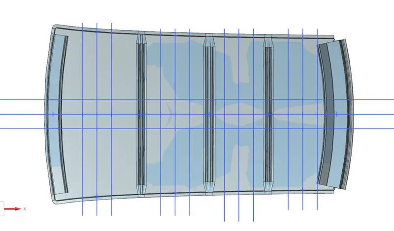
Figure 9. Sketching for projecting points for measurements.
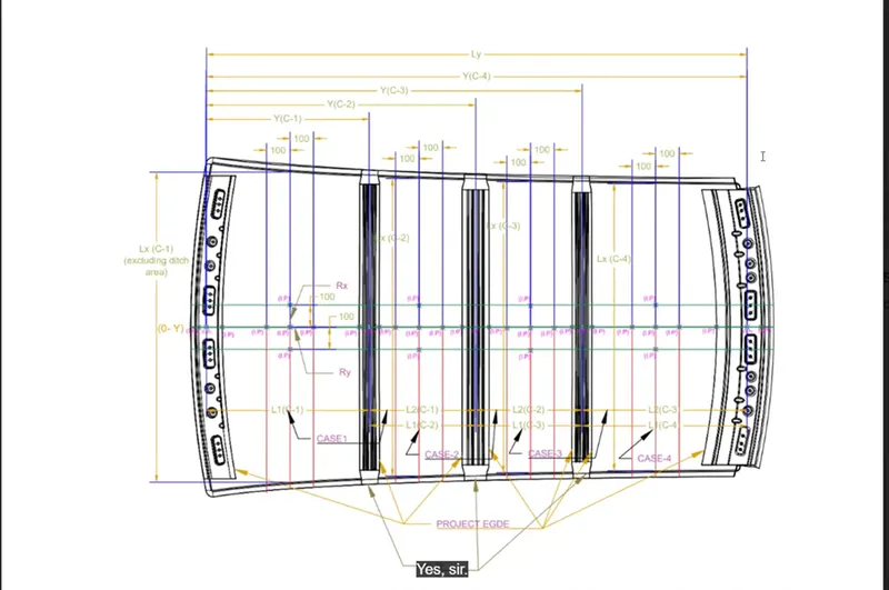
Figure 10. Parameters in snow load prediction.
Calculations
Ly = 1954.27mm
t= 0.75mm
Y for case 1 is the distance between Front roof rail centre to Bow roof 1 centre = 615.29mm
Y for case 2 is the distance between centre of FRR to centre of Centre roof rail = 1081.16mm
Y for case 3 is the distance between centre of FRR to centre of Bow roof 2 =1486.54mm
My for case 1= 823867.15
My for case 2= 943982.41
My for case 3 = 695354.97
Iy for case 1= 1.847x10^3 mm^4
Iy for case 2= 2.035x10^3 mm^4
Iy for case 3= 1.88x10^3 mm^4
L1 for case 1 is the length between FRR and BR1 = 615.29mm
L2 for case 1 is the length between BR1 and CRR = 469.37mm
L1 for case 2 is the length between BR1 and CRR = 469.37mm
L2 for case 2 is the length between CRR and BR2 = 408.34mm
L1 for case 3 is the length between CRR and BR2 = 408.34mm
L2 for case 3 is the length between BR2 and RRR = 482.12mm
|
Section |
Lx |
α |
Rx |
Ry |
S |
Qr |
OK/NG |
|
FRR-BR1 |
1130.28 |
1.05 |
4319.44 |
2936.42 |
542.33 |
13.86 |
OK |
|
BR1-CRR |
1079.07 |
1.099 |
3845.74 |
7176.98 |
438.85 |
7.81 |
OK |
|
CRR-BR2 |
1043.63 |
0.76 |
3856.49 |
16676.10 |
445.23 |
2.94 |
NG |
From the calculations the design is appropriate except for the section CRR-BR2. This shows that the strength should be improved especially at the rear part of the roof. For that embosses should be provided on the roof surface. Since there is only slight difference with the required value exists for the failed section, embosses only at the rear portion will also be fine.
Draft Analysis
The draft analysis technique is used to analyse whether our part model created in CAD is manufacturable based on the draft condition applied. Here the part should get easily removed from the panel dies (in case of Sheet metal part) or mould (in case of plastic). In this project all reinforcements are subjected to draft analysis.
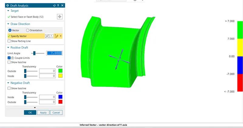
Figure 11. Draft analysis of front roof rail
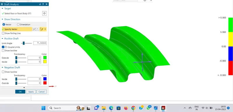
Figure 12. Draft analysis pf Bow roof 1.
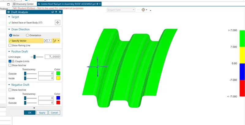
Figure 13. Draft analysis of centre roof rail.
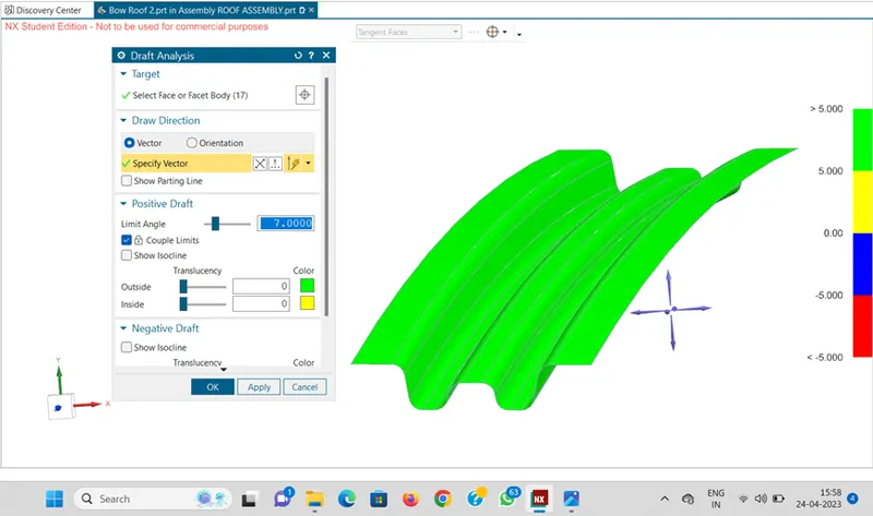
Figure 14. Draft analysis of Bow roof 2.
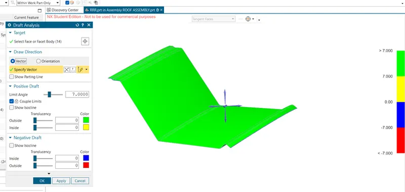
Figure 15. Draft analysis of Rear roof rail.
Conclusion
The roof assembly is designed by using the master sections provided and draft analysis, curvature study and snow load prediction are conducted. After the failure of one section during snow load prediction study, a roof outer panel with embosses was developed and the new embossed surface would be capable of giving enough strength.
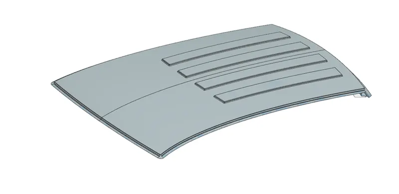
Figure 16. Modified roof with Embosses.