Week 10 - Challenge 1- Attachment Feature Creation (Ribs & Screw Boss)
ATTACHMENT FEATURE CREATION - RIBS AND SCREW BOSS
From the given Class A surface, the component should be created as a closed body. Along with that, ribs and screw boss should also be attached to the body as per the design rules for them.
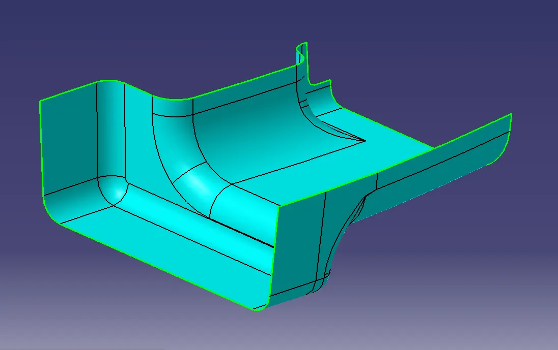
Fig 1. Class A Surface.
The given Class A surface is initially checked using Boundary command and found no gaps on the surface.
Tooling Axis Creation
Tooling Axis is created using bisecting method. In this design, tooling axis is created along Y direction.
- An extract of the flat portion is taken
- A point is created at the centre of the extract and an axis system is created at that point.
- The intersection of the axis system and the surface is taken.
- Two lines are constructed along the side wall and their bisecting line is taken and considered as the tooling axis (temporarily).
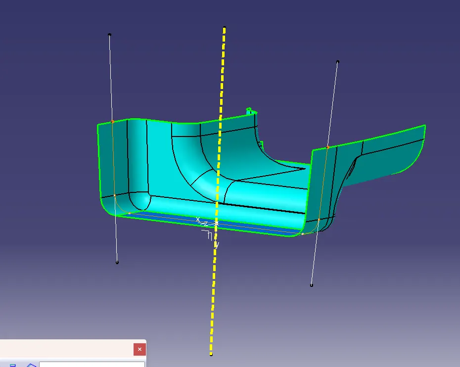
Fig 2. Tooling axis creation.
Draft Analysis on Class A surface
Draft analysis is done on the given Class A surfaceand checked whether the Class A surface clears the draft with the tooling axis considered before.
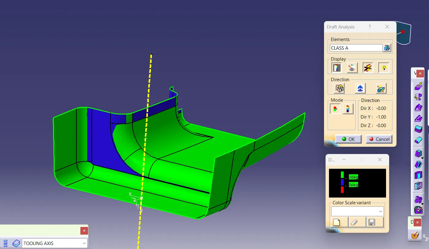
Fig 3. Draft analysis on Class A surface.
Steps for draft analysis:
- In the material view mode, select customize view parameters and select material option.
- Select feature draft analysis command.
- Select the compass icon and place the axis system that appears along the tooling axis.
- Using the colors, check whether the part clears the draft.
Here the part cleared the draft and the tooling axis taken is correct.
Creation of Class B surface
Since the Class A surface is a complex surface, the surface is offseted completely by 3mm inwards to create Class B. While checking the offseted B surface, it was found that a part of the surface went missing.
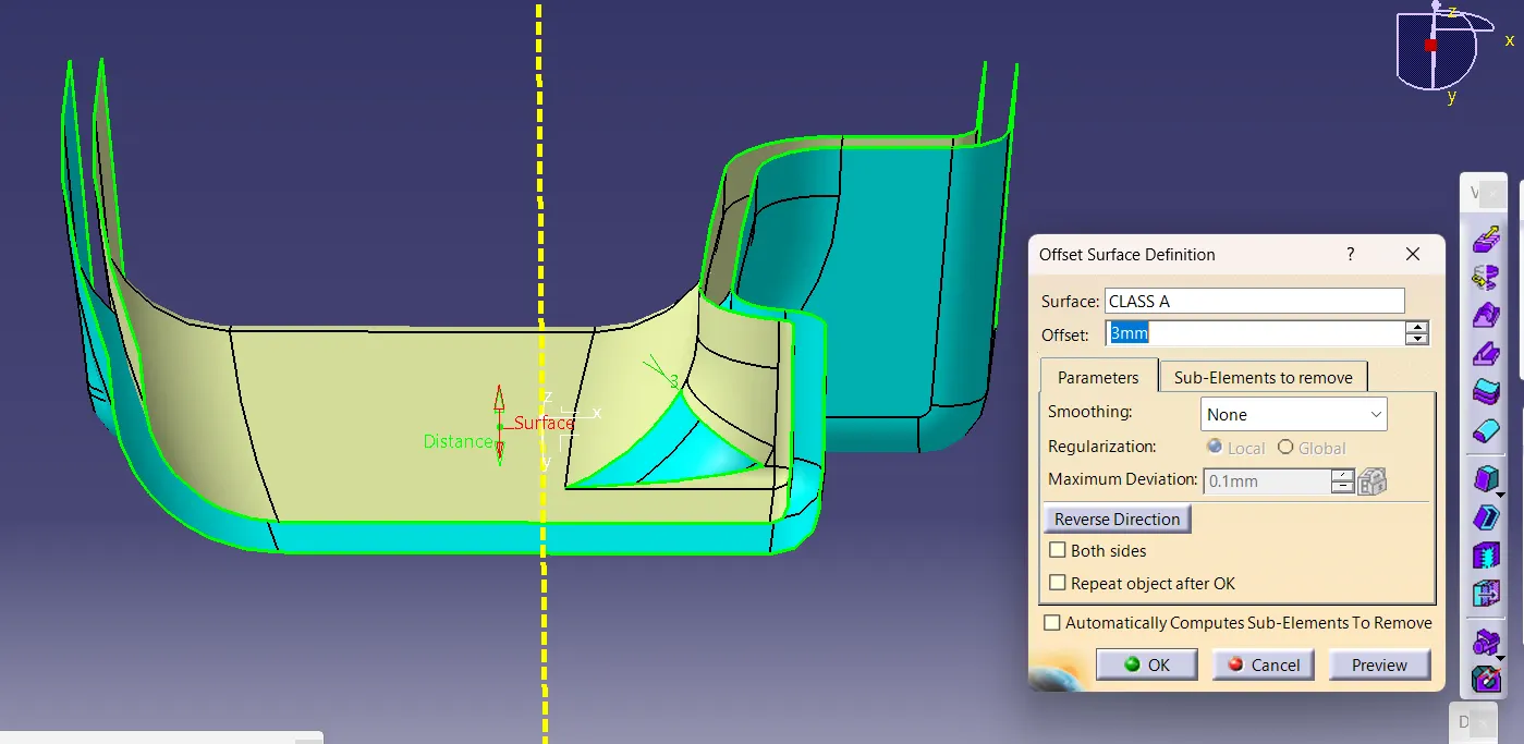
Fig 4. Offsetting class A surface and a part seems missing.
The missing portion was filled using boundary and multi sections surface command.
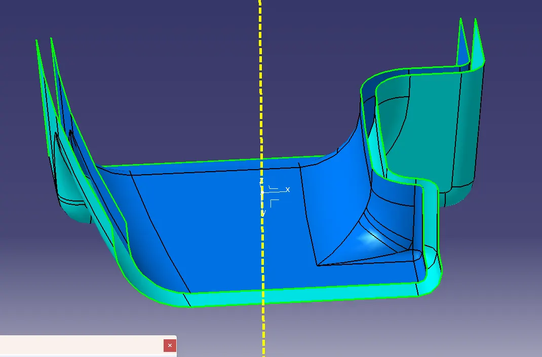
Fig 5. Class B surface.
Class C Creation
The class C surface is created using sweep command from Class A surface boundary, and the draft angle with respect to the tooling axis is taken as 3º for edges which are perpendicular to the tooling axis and 90° with respect to the suface for edges that are parallel to the tooling axis. The bounday cannot be taken in a single stretch. It is extracted as multiple sections using multiple extact and sweep command is used. Then after the neessary trims, Class A is joined with Class C and later trimmed with Class B.
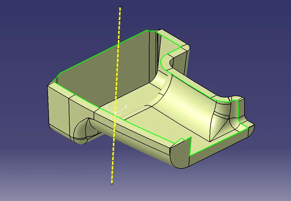
Fig 6. Class A and C is joined together.
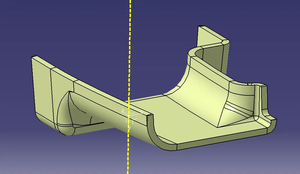
Fig 7. Class A&C join is trimmed with Class B.
The design is then converted into a closed body using Close Surface command in part wokbench.
Rib Creation
Ribs provide stiffness and strength to the component economically without increasing the overall wall thickness. They also facilitate:
- Locating and arresting components of an assembly.
- Providing alignment in mating parts.
- Acting as stops or guides for mechanisms.
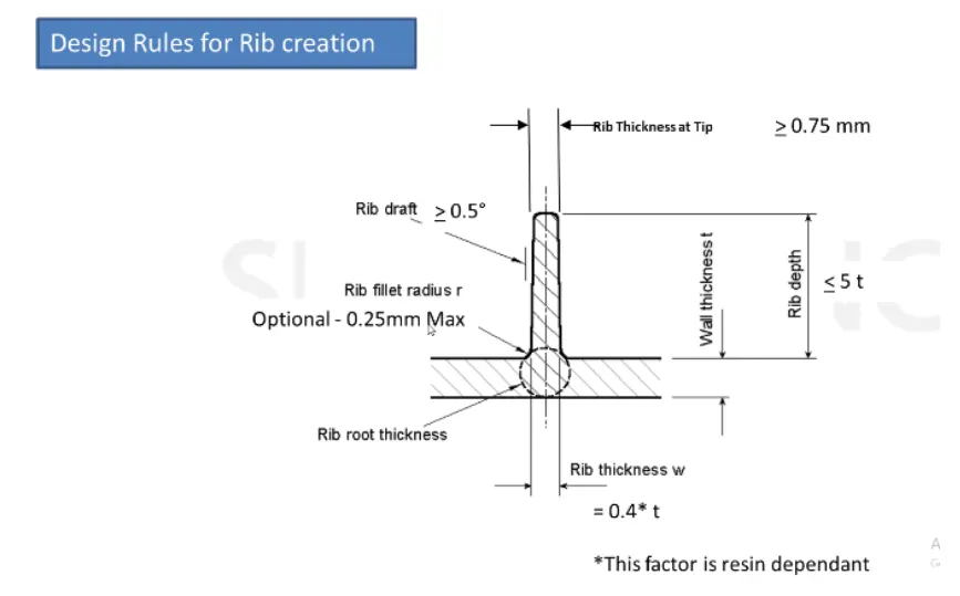
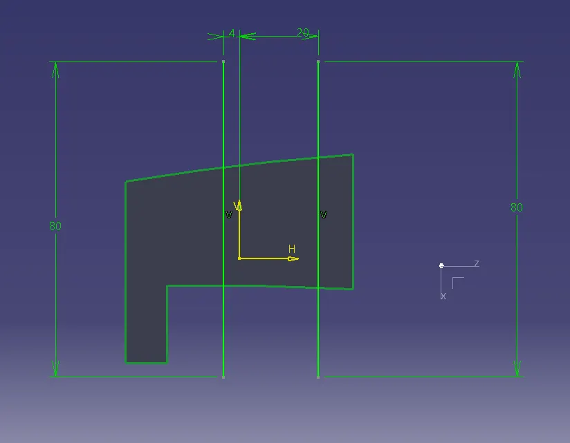
Fig 8. Sketch for rib creation.
- The flat surface where the rib is supposed to come is extraceted and a sketch for rib is constructed.
- The sketch is extruded to a height which is ≤ 5 times base thickness.
- The rib is then thickened to 1.2mm which is 0.4 times base thickness using thicken surface command in part workbench.
- Draft of 0.5° is given for the faces of ribs.
- Using Union Trim boolean operation, ribs are attached to the main body.
- Fillets were provided at the edges with radius of 0.25mm.
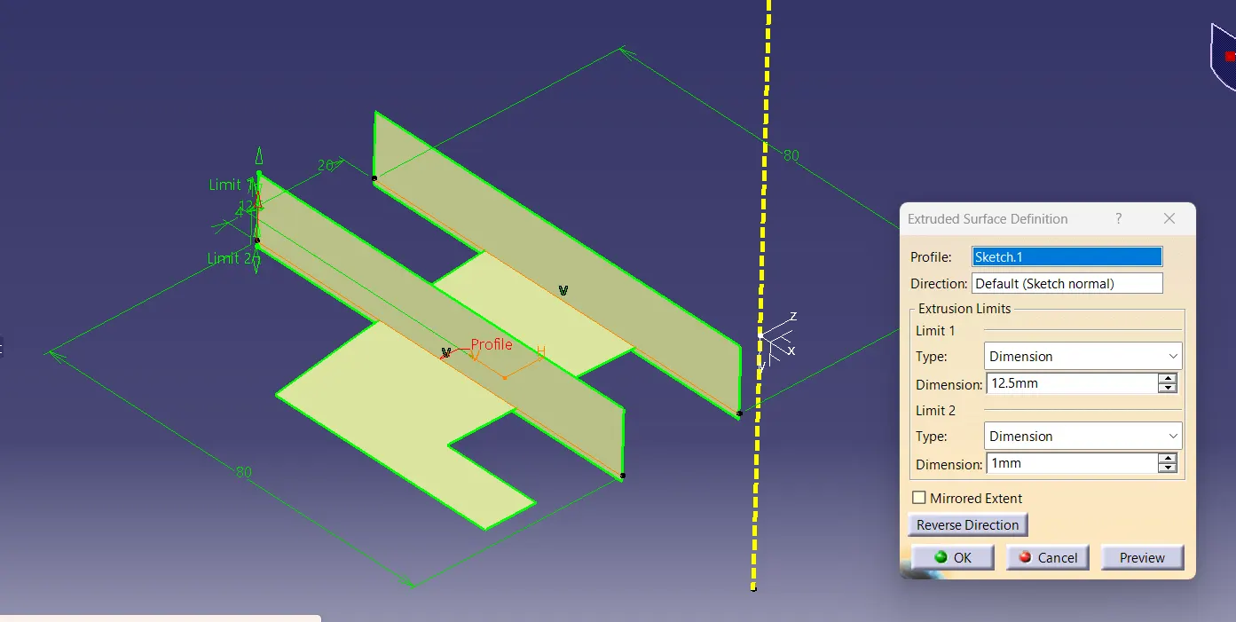
Fig 9. Extruding of ribs.
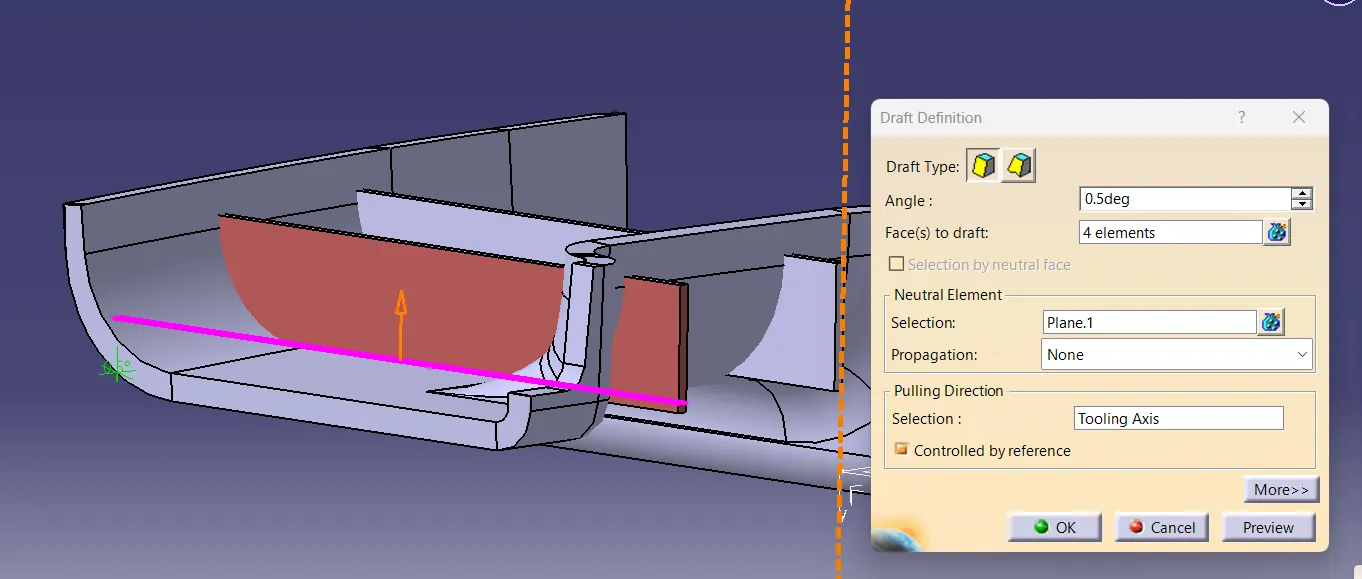
Fig 10. Draft for ribs.
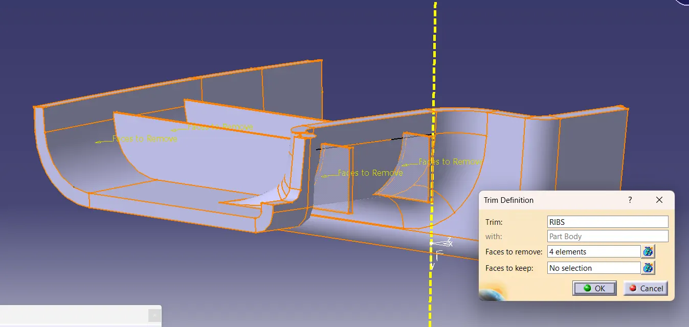
Fig 11. Union Trim.
The rib root thickness was also measured by taking an intersect between YZ plane and part body. A tritangent circle is constructed at the base of the rib and its thickness was measured and the variation with the base thickness was well within 30%.
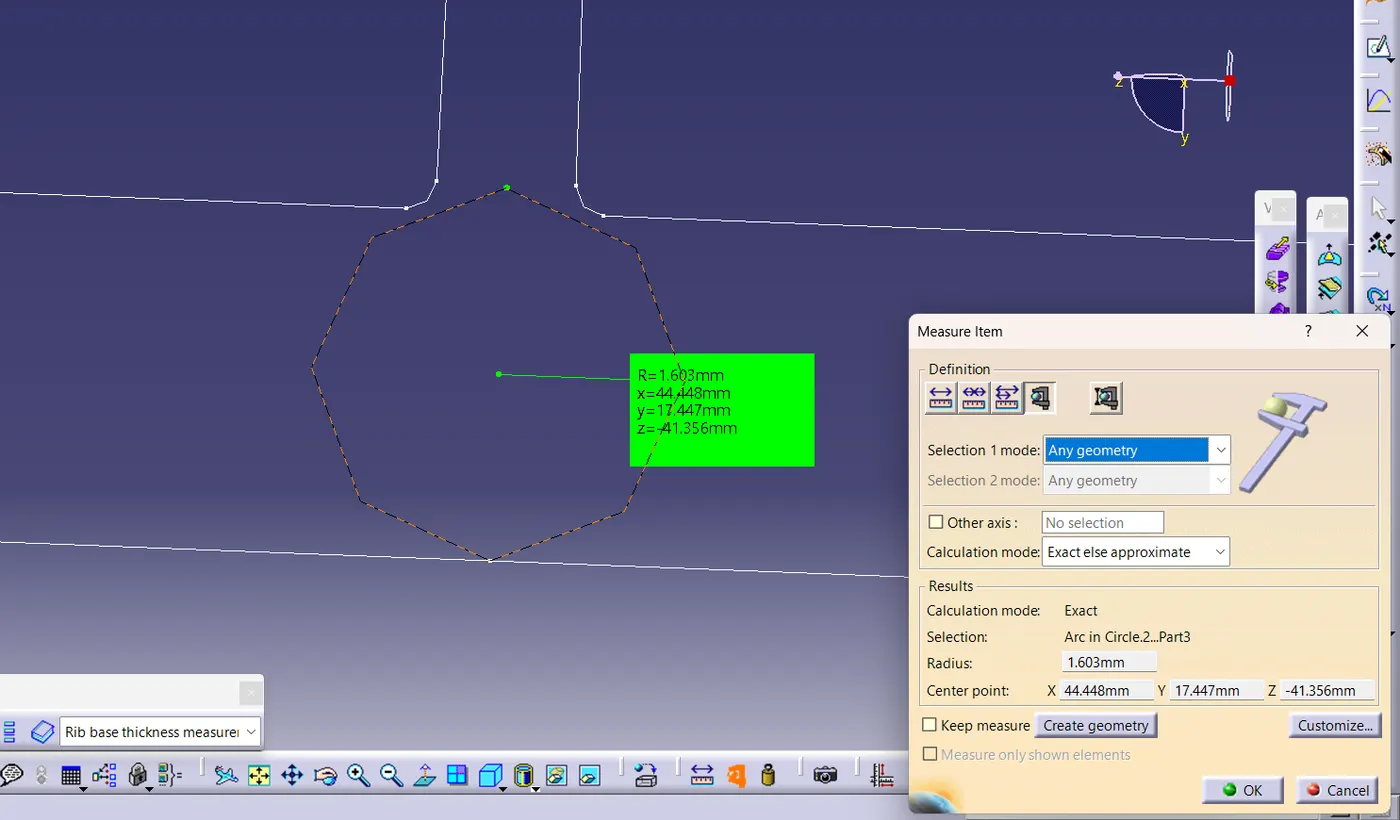
Fig 12. Rib root thickness measurement.
Screw Boss Creation
Bosses are projections designed to accept inserts, self-tapping screws etc. for use in mounting, fastening or assembling parts.
Design Rules for screw boss:
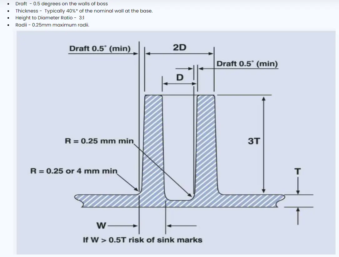
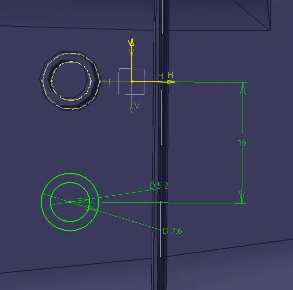
Fig 13. Sketch for screw boss creation.
- The sketch for the screw boss was also is done on the same plane which was used for creating ribs.
- The diamenter of the hole is considered as 5.2mm (M6 size).
- The thickness of the screw boss is given as 1.2mm which is 0.4xbase thickness.
- The sketch is padded to a height of 3mm which is 3xbase thickness.
- A draft of 0.5° are given to the inner and outer walls of bosses, with each of them in opposite directions.
- The screw boss is attached to the main part body using boolean operation Add.
- Fillets of 0.25mm are provided.
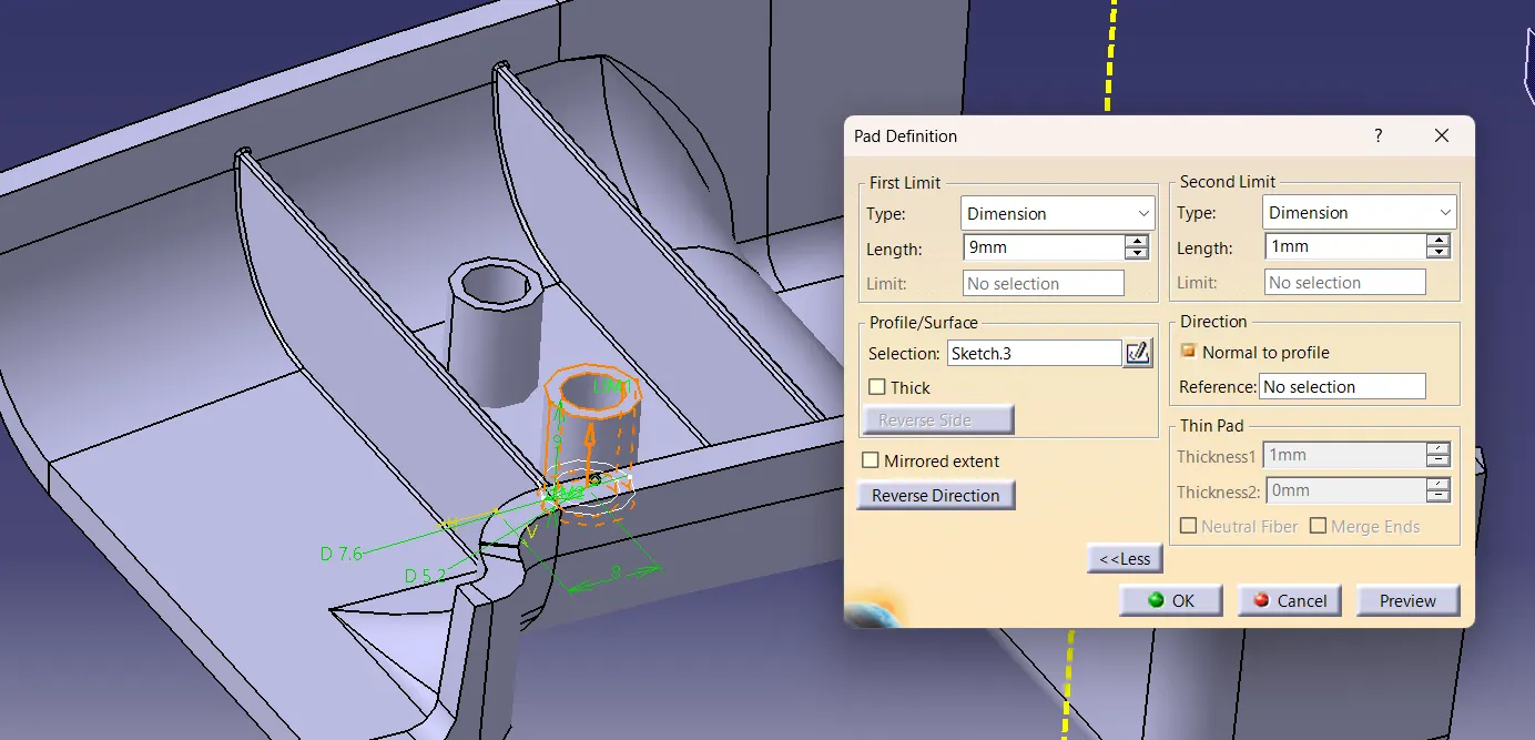
Fig 14. Pad operation.
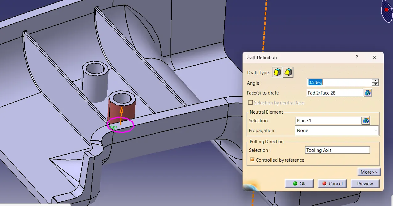
Fig 15. Draft for outer wall.
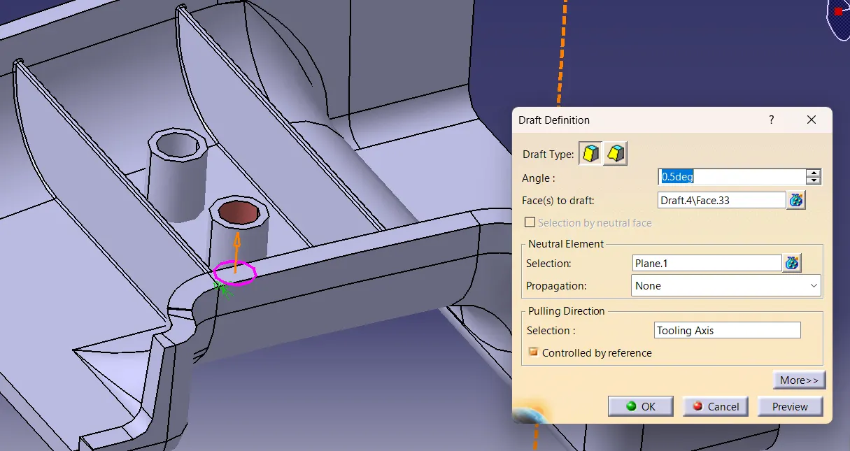
Fig 16. Draft for inner wall.
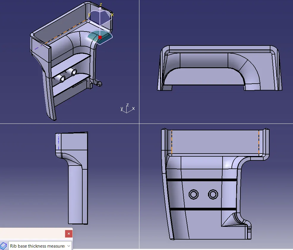
Fig 17. Final design-views.
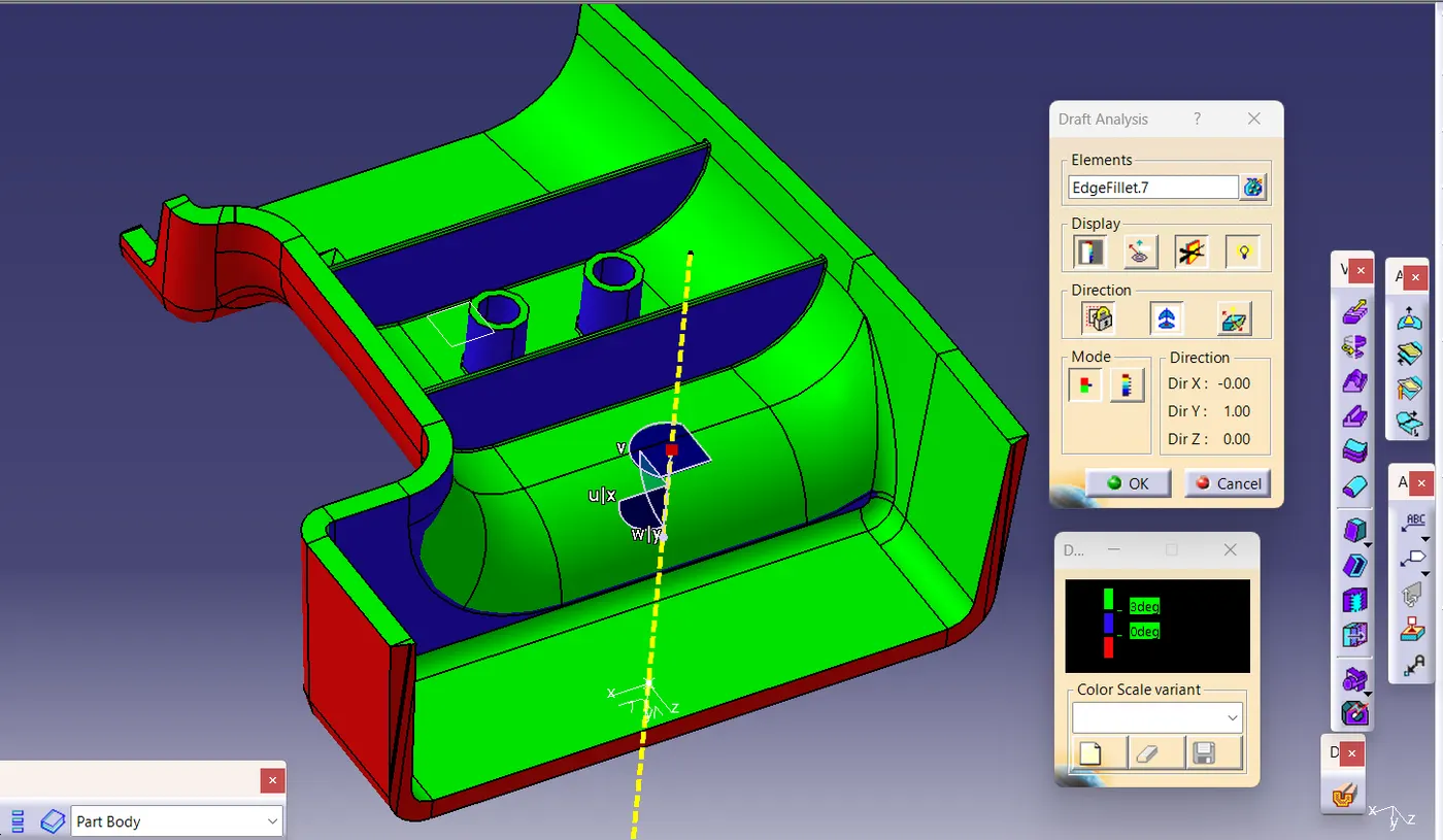
Fig 18. Draft analysis of final design.
- In the material view mode, select customize view parameters and select material option.
- Select feature draft analysis command.
- Select the compass icon and place the axis system that appears along the tooling axis.
- Using the colors, check whether the part clears the draft.
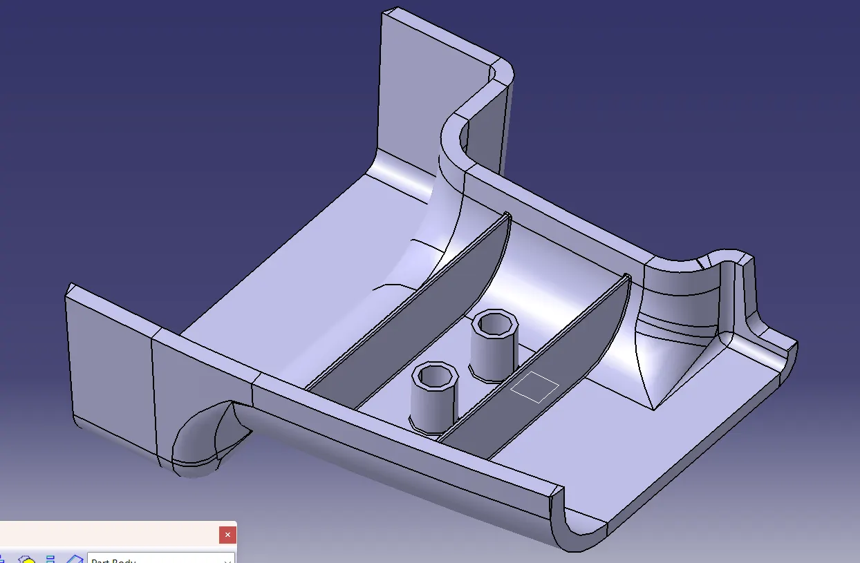
Fig 19. Final design.
Thank You.