Week 9 - Challenge 1 - Base Bracket Design
BASE BRACKET DESIGN CHALLENGE
In this exercise, a base bracket is designed using the given class A surface.
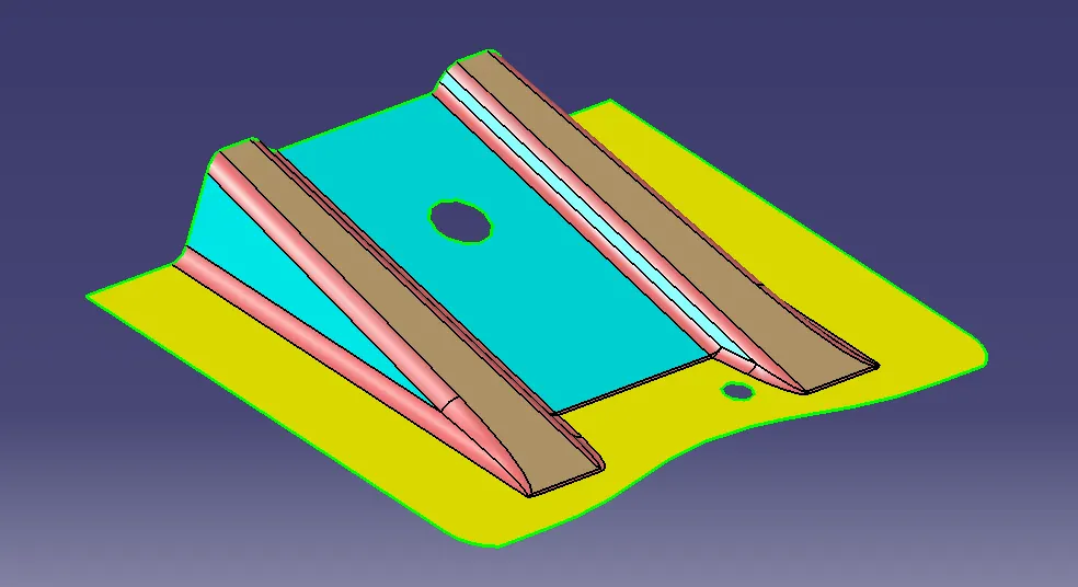
Fig 1. Class A Surface.
Creation of Tooling Axis
Tooling axis is the direction in which the the motion of the core or cavity takes place.
After ensuring there are no gaps in the class A surface, it was determined the tooling direction would be along the Z axis initially due to the presence of the hole. But in order to confirm it, the bisecting method is adopted.
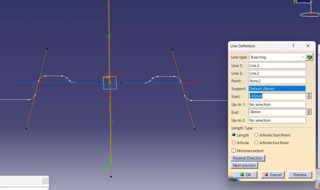
Fig 2. Creating tooling axis using bisecting method.
- Initially, a dummy tooling axis is created at the centre of the hole on the flat slanting surface.
- Take an intersect along the class A suface along YZ plane.
- The ribs of the Class A is the only area that has a chance to be parallel to the dummy axis and to not clear the analysis, so extend the two lines.
- Take a bisecting line for the two extended lines.
- It was found the new line perfectly aligns with the dummy line. Therefore, it is taken as the tooling axis.
Draft Analysis
Draft anaysis is conducted to determine whether the part is manufacturable or not. Here the minimum draft angle is 3degrees.
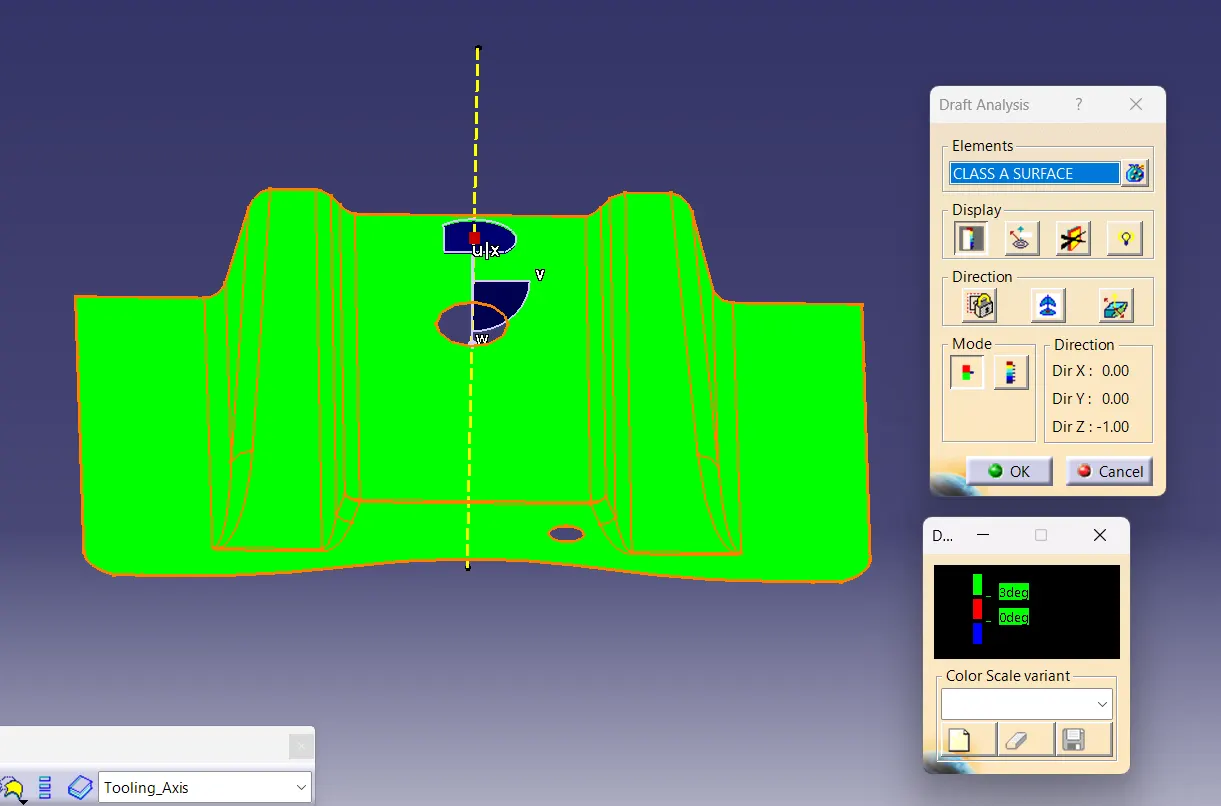
Fig 3. Draft Analysis of Class A surface.
- While doing draft analysis, 'material' option should be activated from the material view icon.
- Then select the command for draft analysis and select the button with axis.
- Bing the axis bar and align with the tooling direction.
- Check whether the part clears the draft analysis.
Creation of Class B surface
For creating Class B surface, the two ribs, the slanting face and the flat face are extracted from Class A and offseted by 2.5mm, which is the thickness of the part.
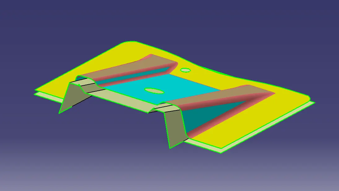
Fig 4. Class B offseted from Class A.
After separately extracting and offseting the ribs and flat surfaces, they are trimmed with each other and unwanted surfaces are omitted.
Class C creation
Class C is the surface which connects Class A and Class B surfaces according to the draft angle and tooling direction.
Class C surface is created using the Sweep command and the boundary of the class A and holes are taken as guide curves. The draft angle is given as 3 degrees.
The Class C suface is then joined with Class A and trimmed with Class B.
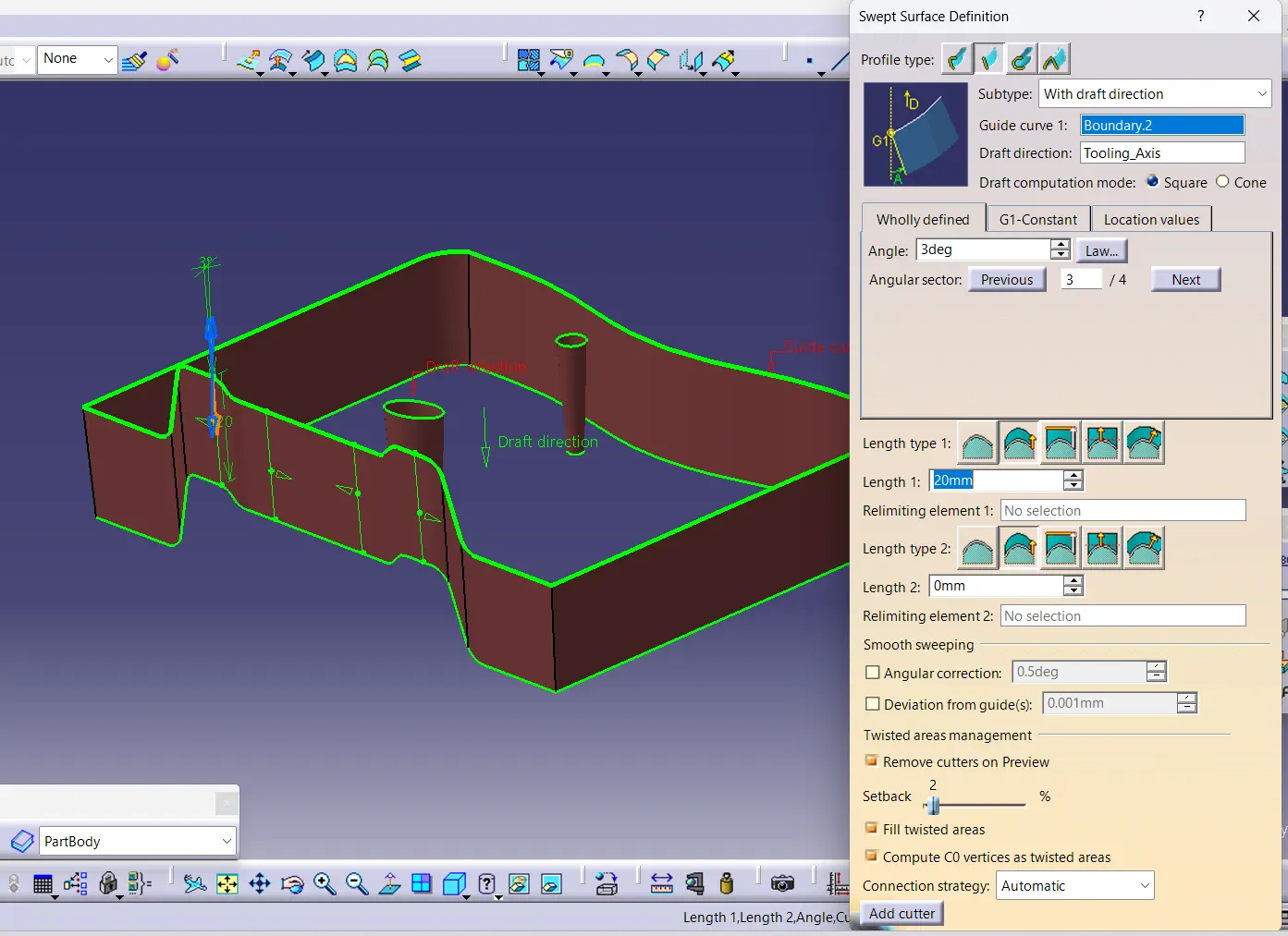
Fig 5. Class C Surface
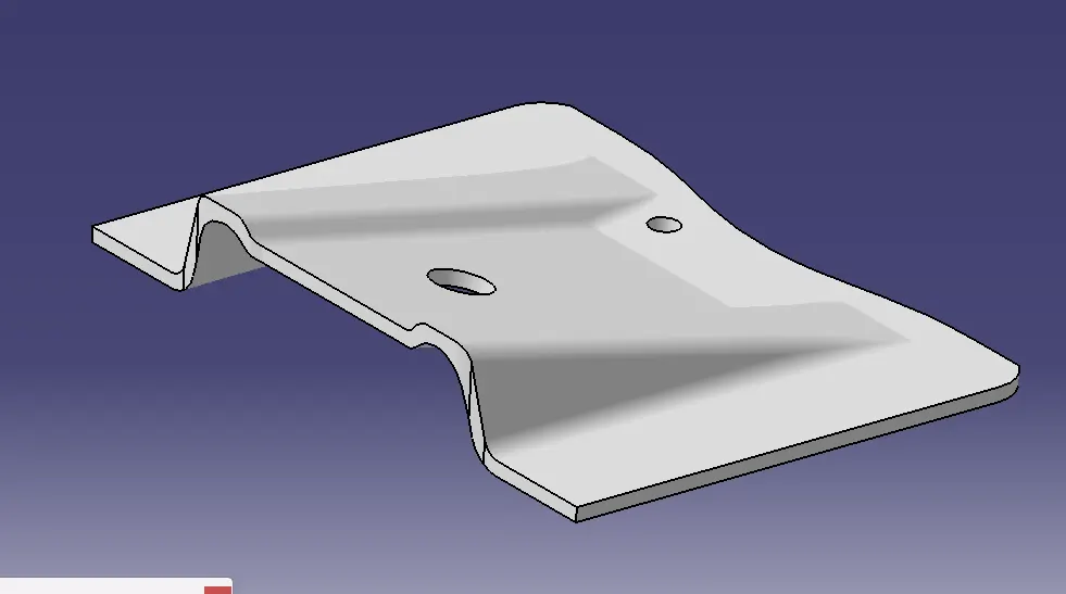
Fig 6. Final design after converting to Closed body using Close Surface.
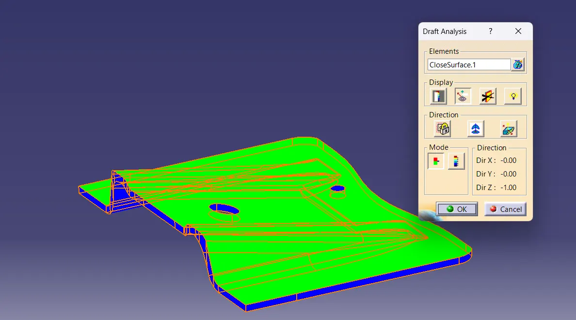
Fig 7. Draft analysis of the final design.