Week 10 - Challenge 3 - Door Trim Lower with Engineering Features
Week 10 - Challenge 3 - Door Trim Lower with Engineering Features
- OBJECTIVE:-
- Create the Door Trim Lower Plastic component through the given Class-A surface.
- perform the Draft analysis on the model.
- Create the Heat Stakes and the locators considering the design rules.
- ASSUMPTION:-
- Component material A.B.S "Acrylonitrile butadiene styrene"
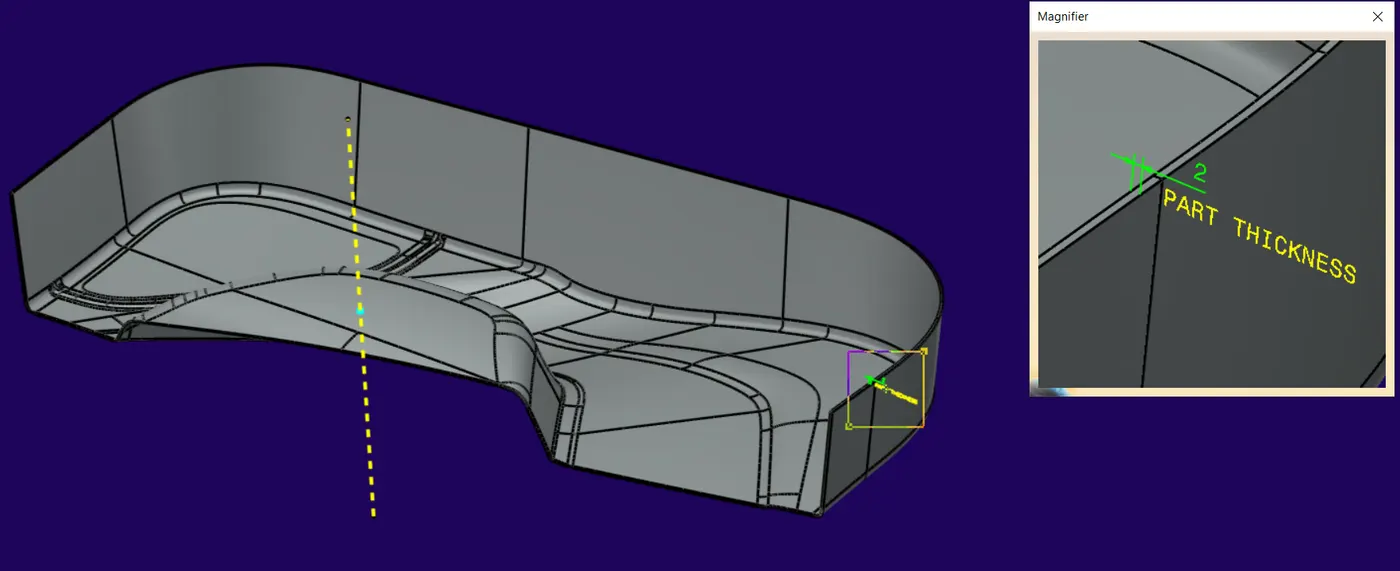
- The thickness of the component is 2 mm.
- Recommended thickness value WRT Material "ABS" = min.= 0.8 mm , Average = 2 mm , max. = 3.2 mm
- ------------------------------------------------------------------------------
- Different views of the MODEL:-
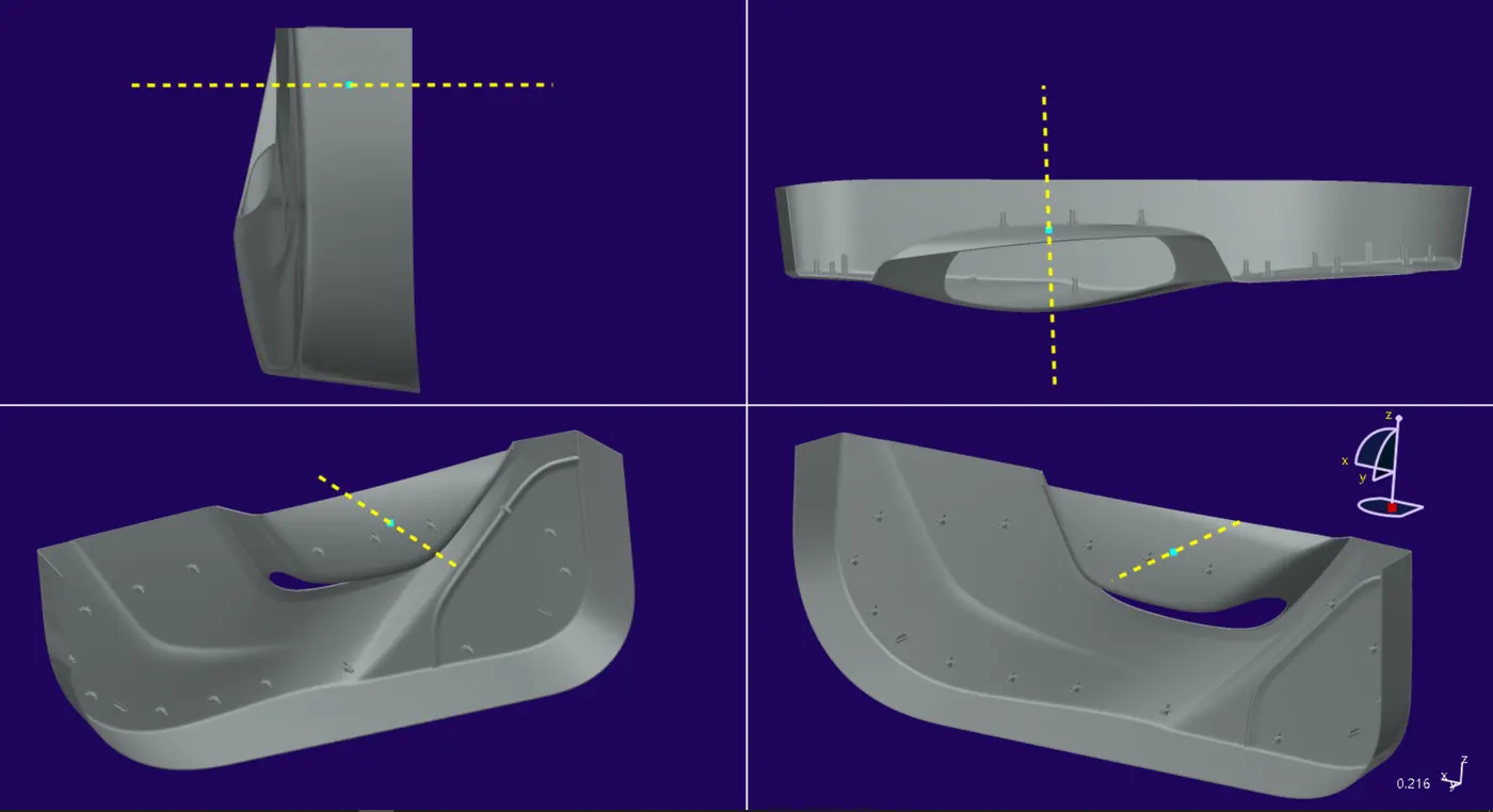
- Consideration while designing the model:-
-
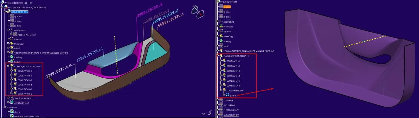
The distance between each point of the edges of two neighbouring patches must comply with the following limits:
-
For class A: no more than 10 µm = 0.01 mm
-
For class B: no more than 20 µm.= 0.02 mm
-
For class C: no more than 50 µm.= 0.05 mm
-
The angle between the tangents to the surface on the edges of two neighbouring patches must comply with the following limits:
-
For class A: no more than 6’ = (0.1◦).
-
For class B: no more than 12’ = (0.2◦).
-
For class C: no more than 30’ = (0.5◦).
-
(Note:- ( ’) _means minute:- (ex. conversion of minute to degree: - 6’ = 6/60 = 0.1 degree)
-
------------------------------------------------------------------------------
- Expanded tree view with model construction steps:-
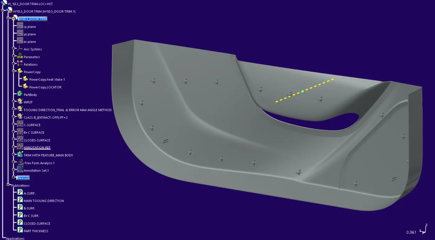
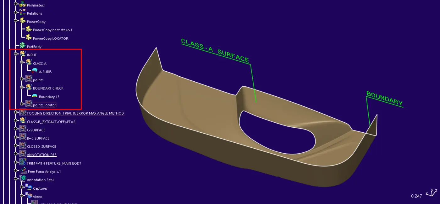
- CLASS-A SURFACE INPUT AND BOUNDARY CHECK
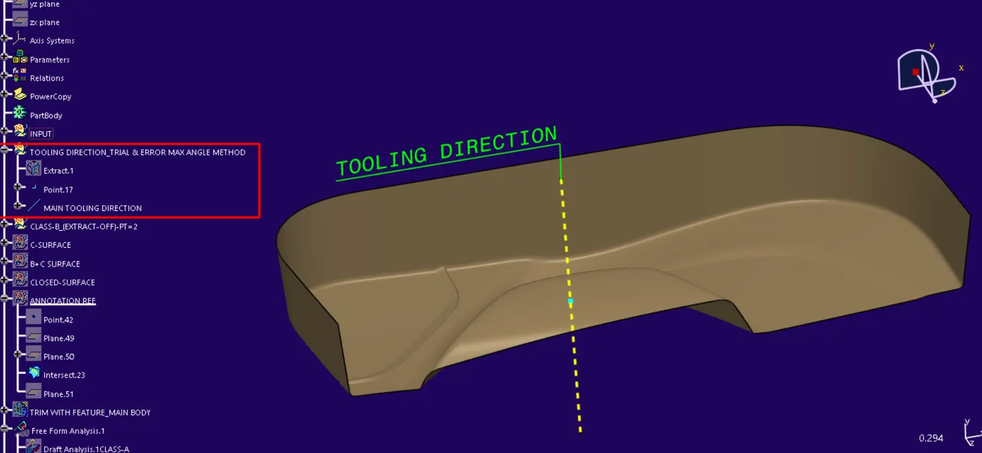
- TOOLING AXIS.
- DEFINITION:-
- Tooling axis:- “ main tool axis” is the axis that defines the mould opening direction.
- The tooling axis must be created on a feature like a hole, slot, cut-out, flat surface, or continuous surface of a Class A Surface.
- The tooling axis justifies the angle sector of the side wall draft ”C-surface”, the positive angle of the C surface in the direction of the ejection, “i.e. it creates a relation of the component from mould opening to the ejection of part”.
- The tooling axis must be created in such a manner that gives the ejection clearance and mould opening clearance such no undercut will come in the way during ejection and mould opening,
- it also provides the reference axis to the slider axis or angled pin axis, which is used for the undercut inserts, (known as the undercut at an angle of tool axis),
- While designing mould tools, it is practised that the ejection pins - straight action form pins must be constrained to move parallel to the tooling axis.
- Straight action form pin these pins are ejection pins used to release the Internal undercuts”,
- similarly, sliders are used to remove the external undercut.
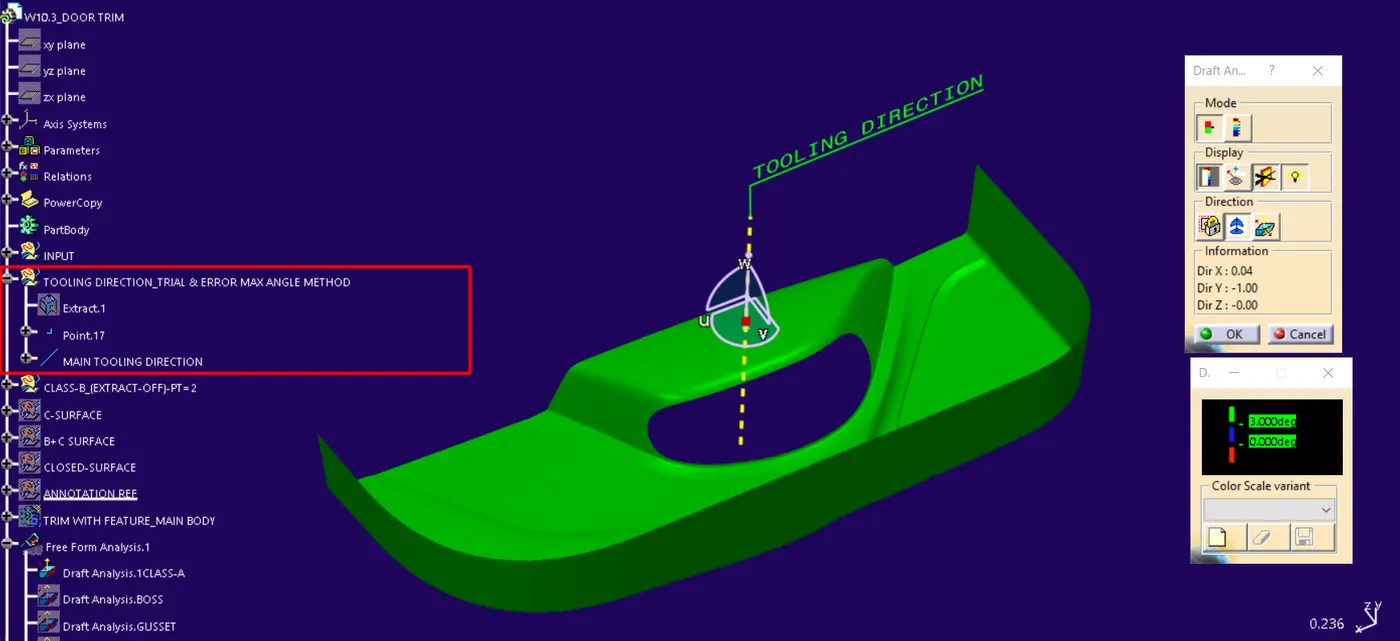
- METHODOLOGY:- " APPROXIMATION_TRIAL & ERROR METHOD "
- In this method, tooling direction is found with the help of draft analysis.
- method:-
- 1. APPROXIMATION: -
- Set A SURFACE IN SUCH A VIEW WHERE ALMOST ALL SURFACE ARE VISIBLE
- AT THAT VIEW LOCK THE COMPASS DIRECTION
- CREATE A LINE IN THE DIRECTION OF THE LOCKED COMPASS DIRECTION.
- 2. TRIAL & ERROR :-
- BY DRAFT ANALYSIS SET COMPASS ONLINE CREATED BY APPROXIMATION
- AND SET THE COMPASS IN SUCH A WAY THAT IT FULL FILL THE DRAFT ANALYSIS WITH (START WITH MIN. ANGLE OF 1.5 DEG TO 3 DEG)
- AFTER FULL FILLING DRAFT ANALYSIS LOCK THE COMPASS DIRECTION
- CREATE A LINE IN THE DIRECTION OF THE LOCKED COMPASS DIRECTION
- THAT ABOVE-CREATED LINE WILL BECOME THE MAIN TOOLING AXIS AS SHOWN IN BELOW IMAGE:-
-
- ------------------------------------------------------------------------------
- B-SURFACE "DIFFERENT VIEWS"
- (view mode_shading with edges without smooth edges):- This mode is used to check the discontinuity of patches on the surface.
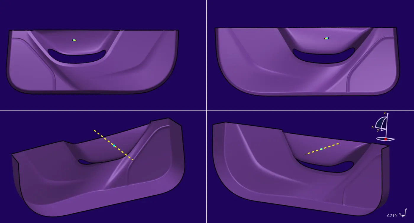
- FINAL B-SURFACE
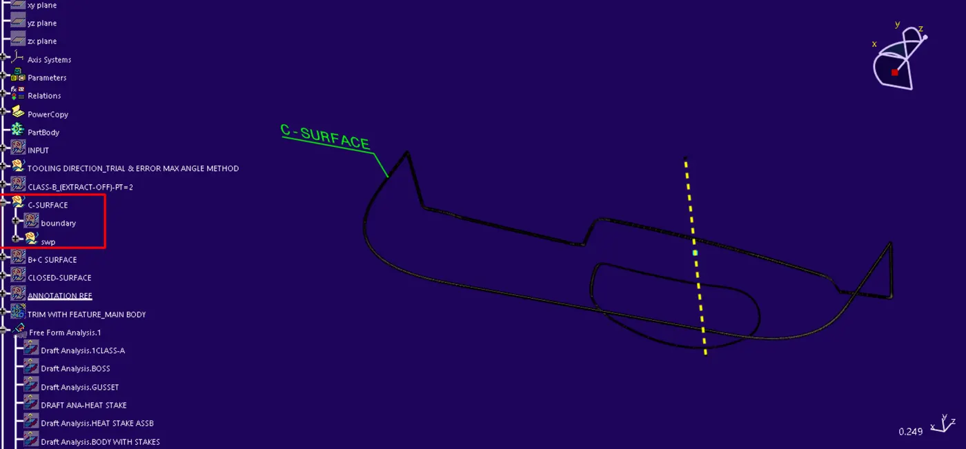
- C-SURFACE
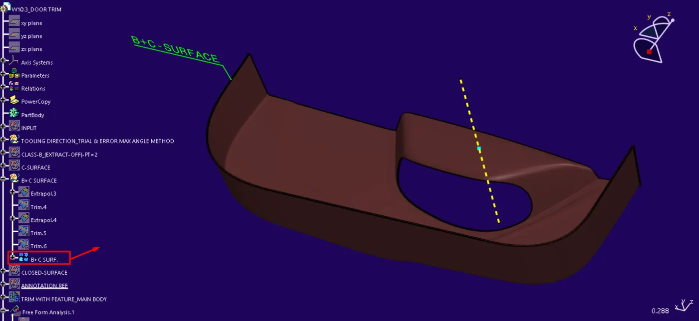
- B+C SURFACE
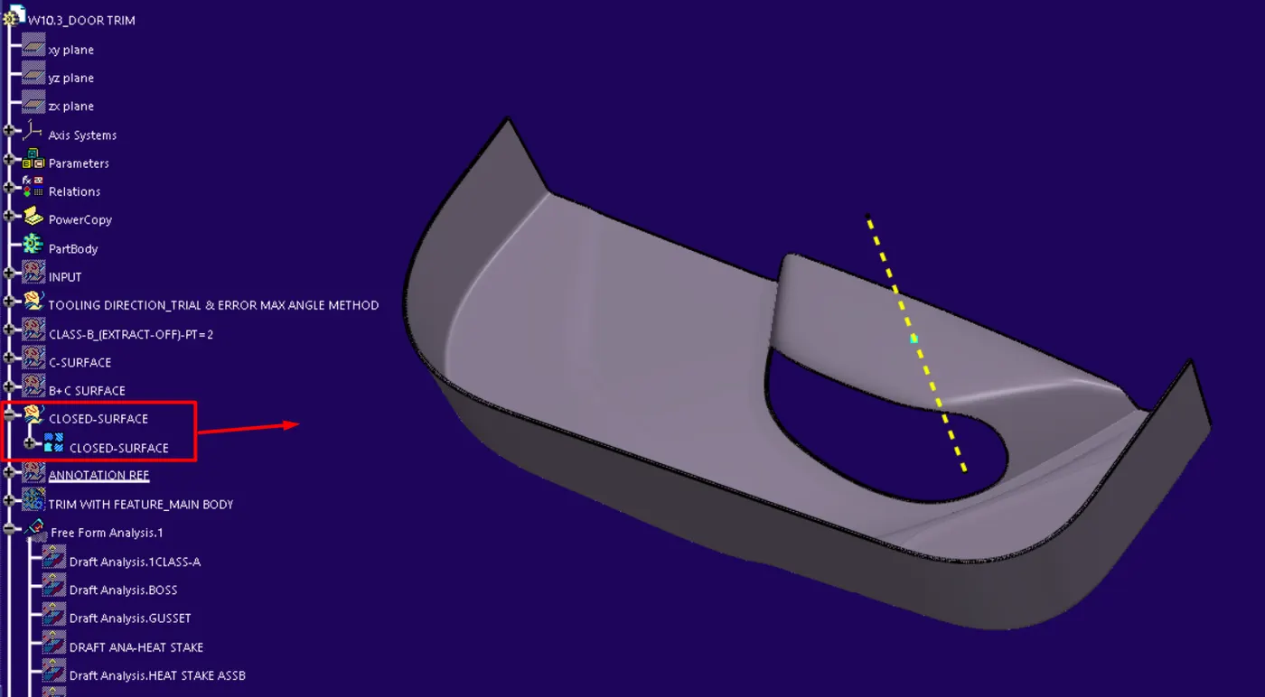
- CLOSED-SURFACE
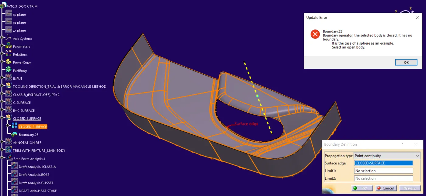
- CLOSED-SURFACE-BOUNDARY CHECK
- SOLID BODY:- from a closed surface
- ------------------------------------------------------------------------------
- B-SIDE FEATURE :- HEAT STAKES & LOCATORS
- DEFINITION:-
- LOCATORS:-
- It is used to locate the component with the mating part, in the aligned position. (as it guides the assembly of the two mating parts)
- It restrained the degree of freedom.
- it is a tower-like structure of two or four ribs. (2-point and 4-point locator)
- height must be considered as it is the first element that came in contact with the mating part hole to align the assembly.
- Long locators can be designed directly on the part surface but lead to higher shrinkage and locator buckling
- so for longer locators, it is preferred to be designed on an extension like the dog house.
- design guidelines shown in the below images
- HEAT STAKES:-
-
Thermal staking or Heat stacking provides an alternative to welding when the two parts consist of dissimilar materials which cannot be welded or when simple mechanical retention of one part relative to another is adequate (i.e. as opposed to molecular bonding).
-
A hole in the metal part receives a pre-moulded plastic boss. The thermal tip contacts the boss and creates localized heat
-
As the boss melts, the light pressure from the horn forms a head with a shape determined by the horn tip configuration.
-
When the heat is terminated, the plastic material solidifies and the dissimilar materials are fastened together called riveting
-
Hot air staking is an economical fixing method that simplifies recycling.
-
Joints are permanent.
-
More small stakes are better than a few thick ones.
-
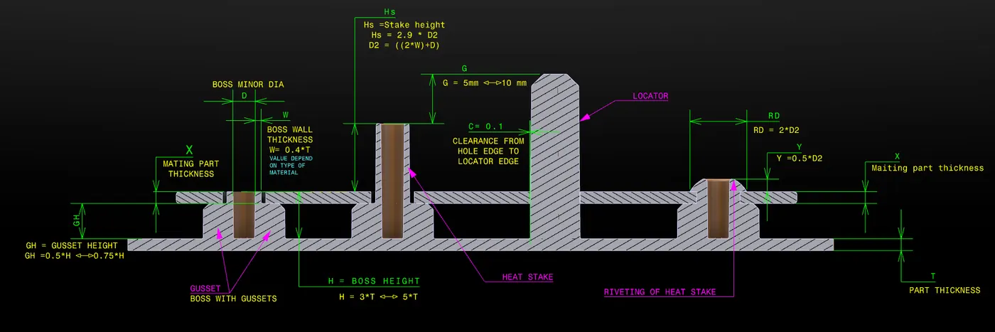
Keep the stake forming height to the recommended limit.(i.e stake height = 2.9 * boss outer dia)
- APPLICATIONS:-
- The most commonly used application involves the attachment of metal to plastic.
- Applications range from staking plastic bosses for the assembly of car door panels to joining PCBs to plastic housings.
- Benefits
- this technique includes no vibration damage, no particulates, the ability to stake metalized coated applications and the capability to stake in difficult-to-access or restricted areas.
- PROCESS:-
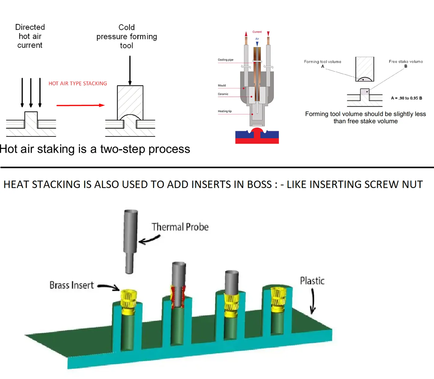
- THE TYPE OF HEAT STAKE USED IN THIS MODEL IS A HOLLOW STAND OF TYPE STAKE:-
- HOLLOW STAKE:-
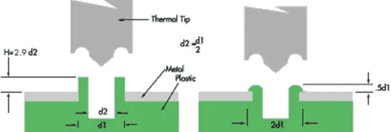
- NOTE:- Bosses with an OD in excess of 5/32 inch (4 mm) should be made hollow.
- DESIGN GUIDELINES TO FOLLOW WHILE DESIGNING STAKE AND LOCATORS AS SHOWN BELOW IMAGE:-
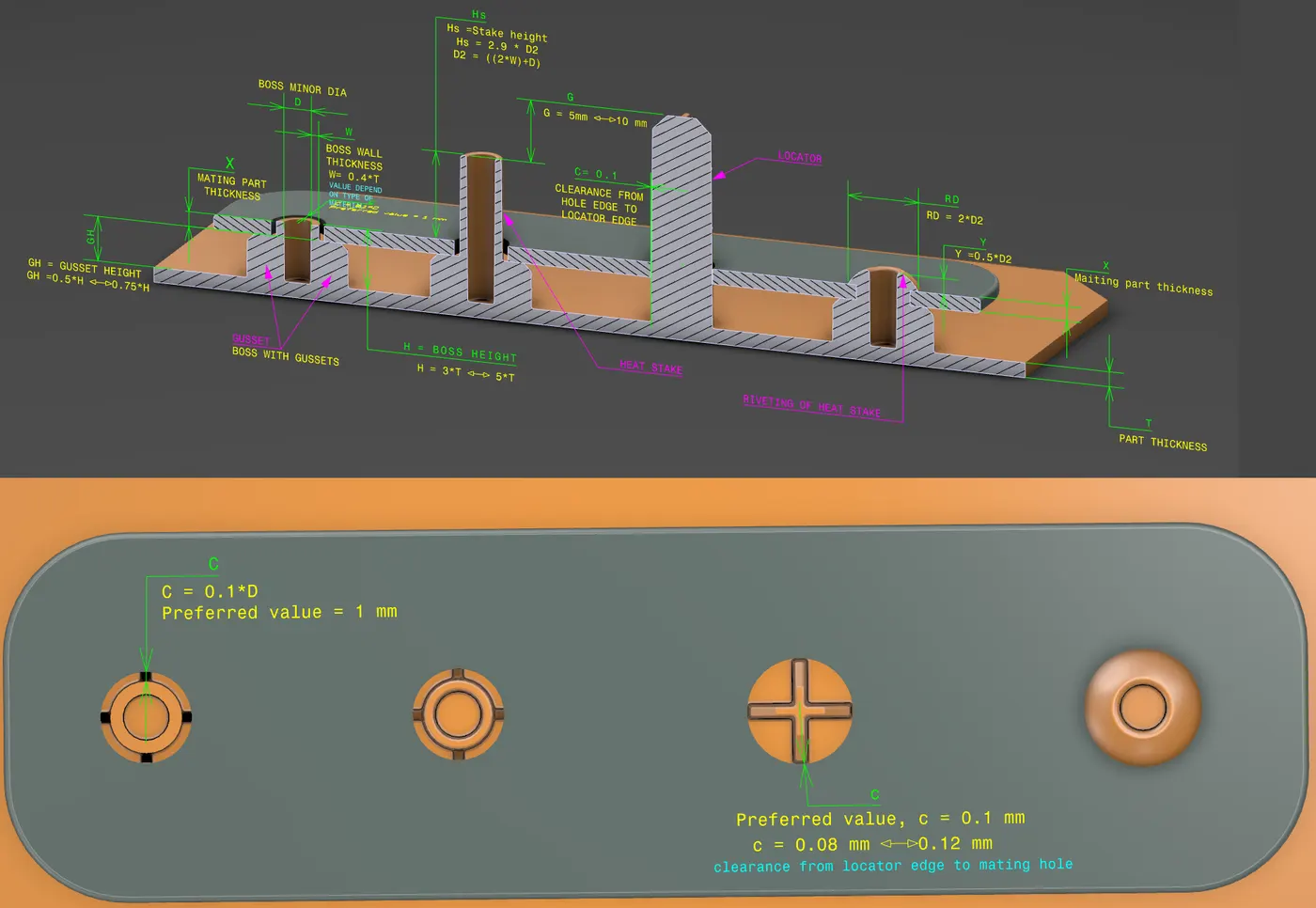
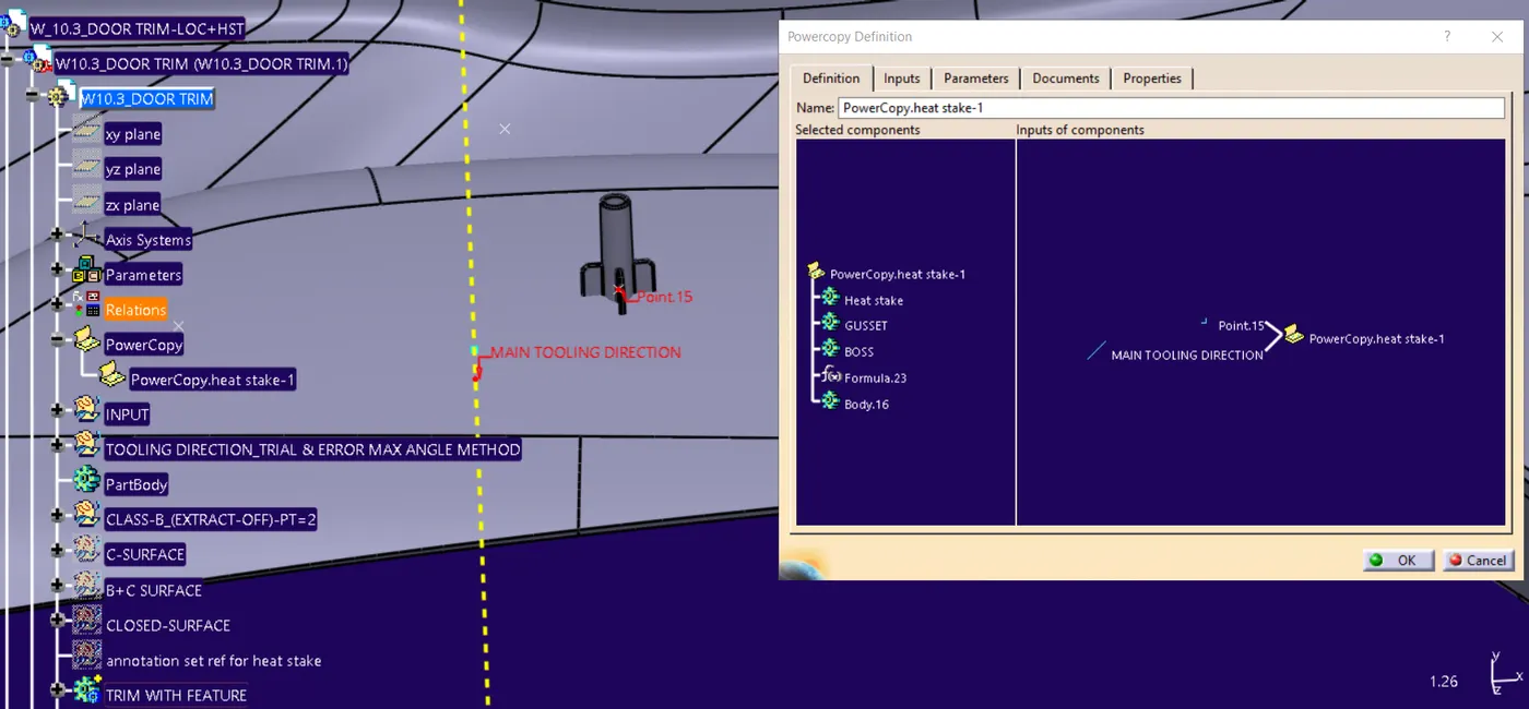
- FEATURES:- HEAT STAKE AND LOCATOR DESIGN IN MODEL_DOOR TRIM
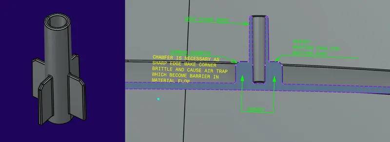
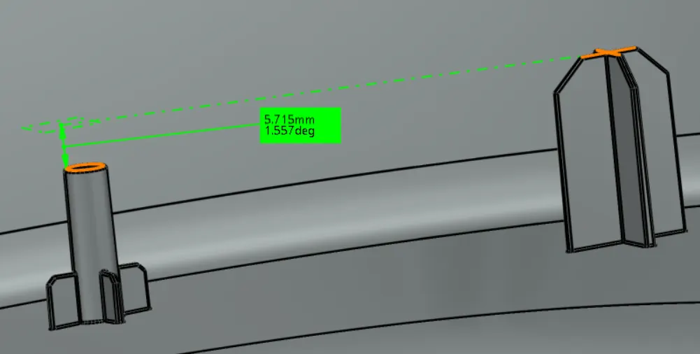
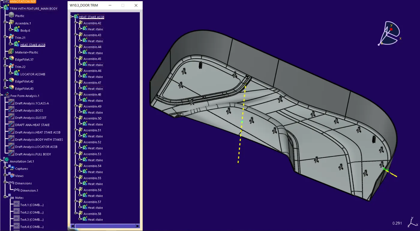
- POWER COPY OF HEAT STAKE (WRT TO TOOLING DIRECTION)
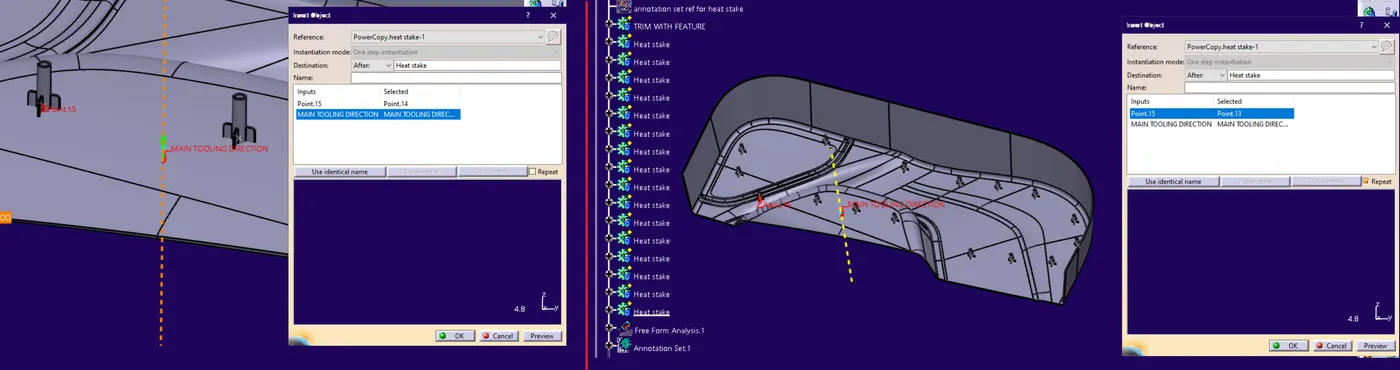
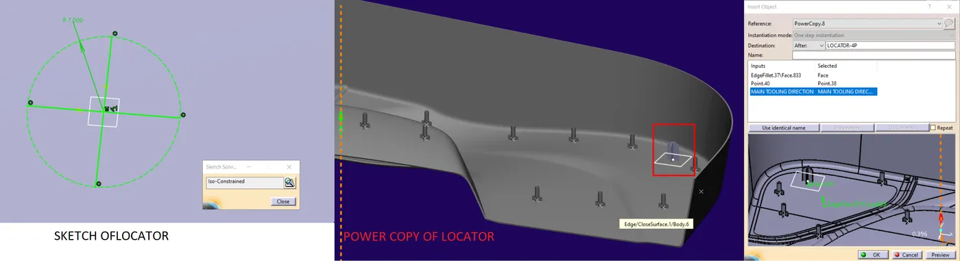
- POWER COPY OF LOCATOR (WRT TO TOOLING DIRECTION)
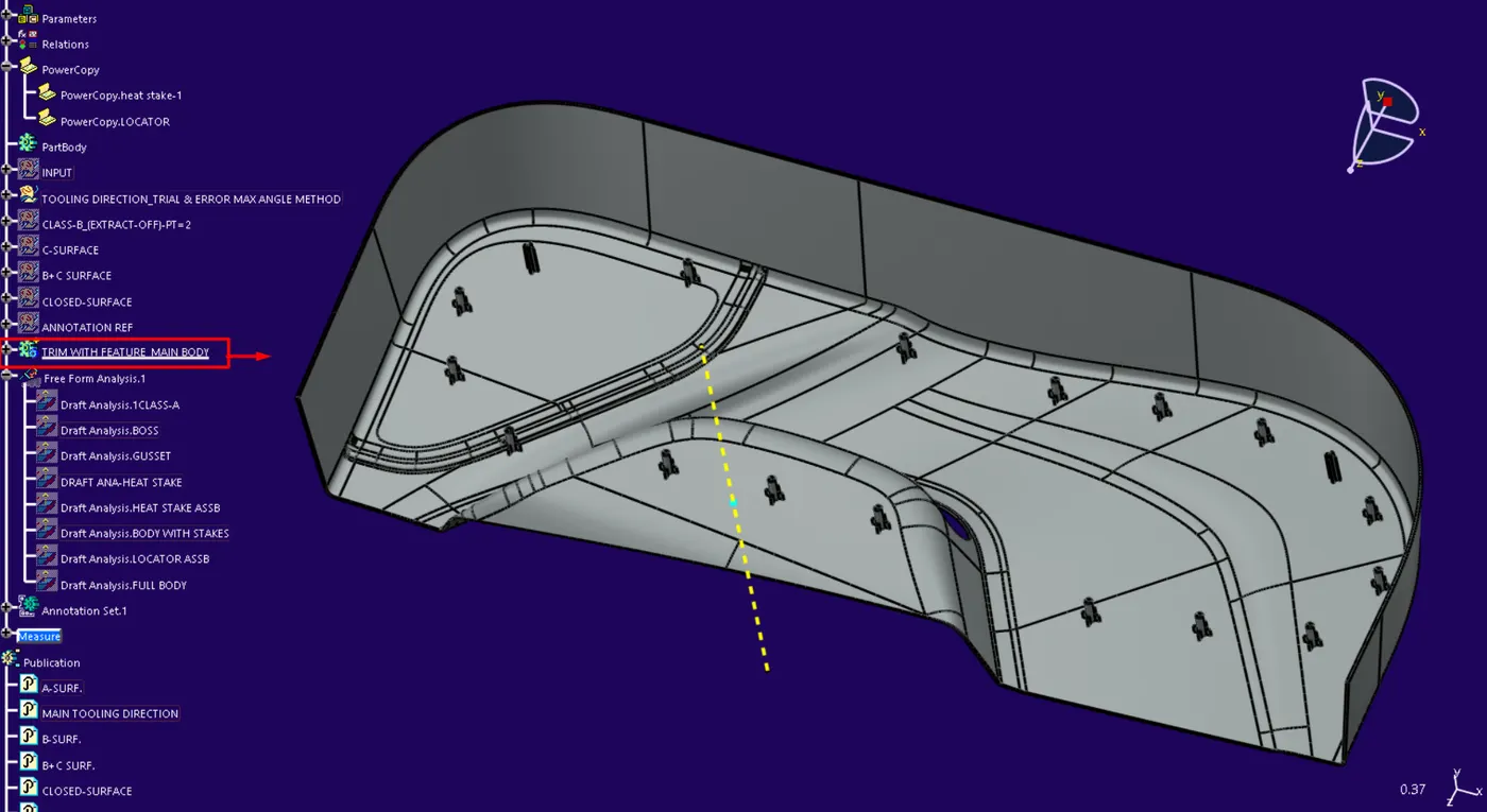
- FINAL BODY VIEW WITH FEATURES
- ------------------------------------------------------------------------------
- DRAFT ANALYSIS:-
- DEFINITION:-
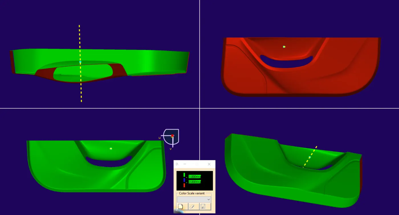
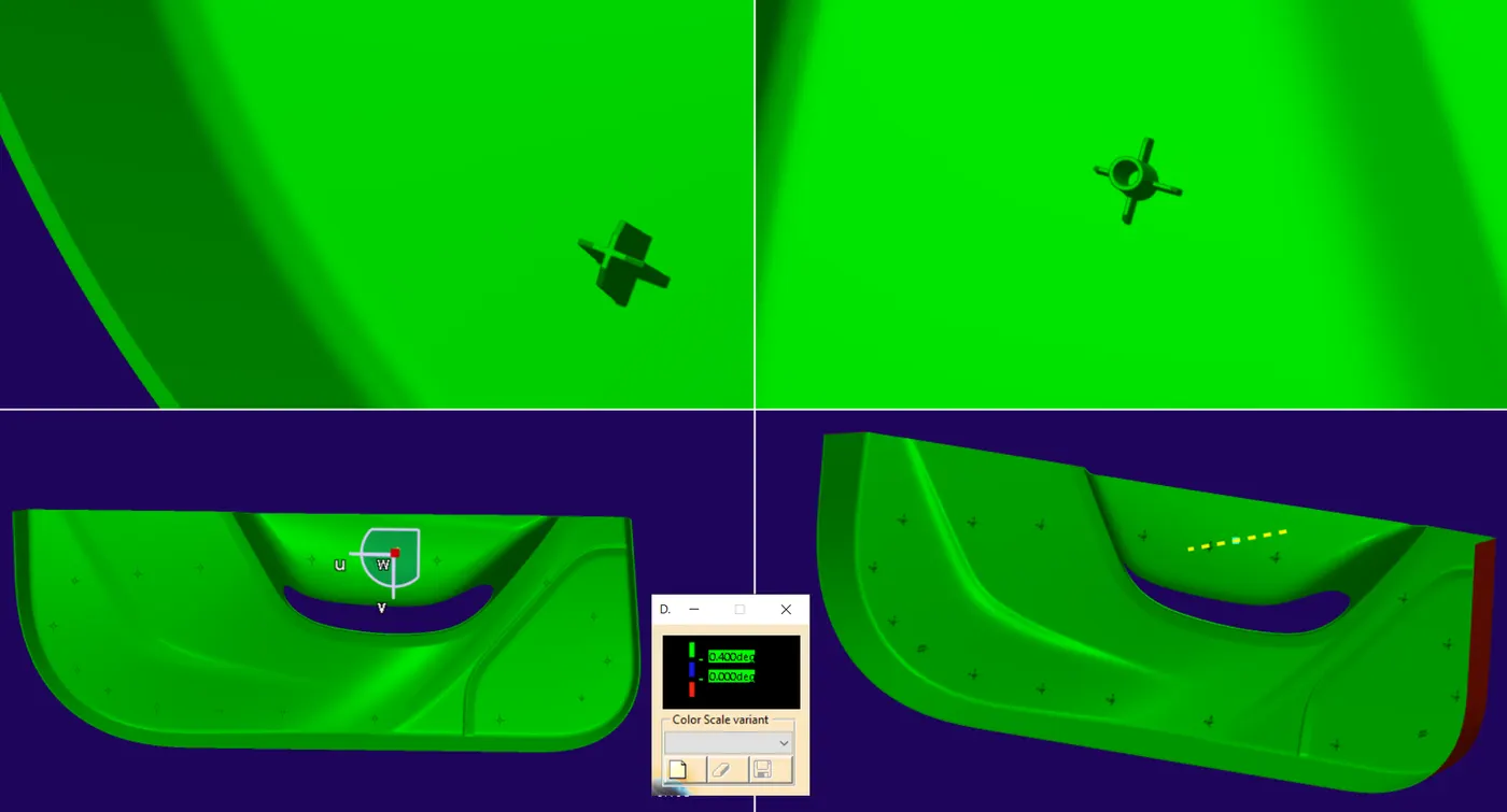
- The Draft Analysis enables you to detect if the part drafted will be easily removed “EJECTED”
- The analysis is performed based on colour ranges identifying zones on the analyzed element where the deviation from the draft direction at any point, corresponds to specified values”
- DRAFT ANALYSIS COMPASS:-Terminology

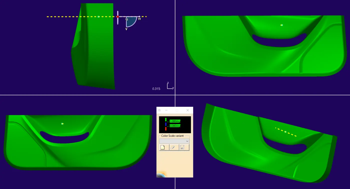
- DRAFT ANALYSIS OF CLASS A SURFACE.
- DRAFT ANALYSIS OF SOLID BODY WITHOUT FEATURE
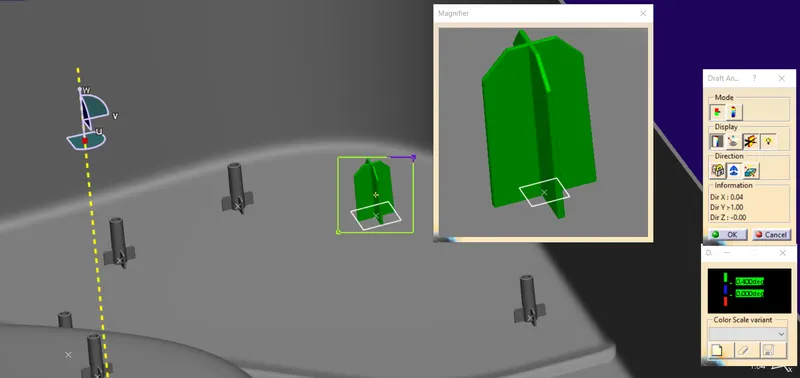
- DRAFT ANALYSIS OF FEATURES
- DRAFT ANALYSIS OF HEAT STAKE
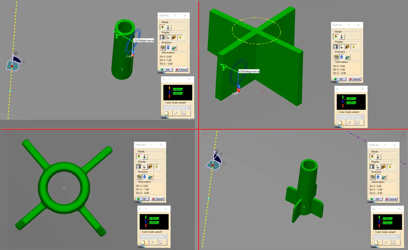
- DRAFT ANALYSIS OF LOCATOR
- DRAFT ANALYSIS OF THE FINAL BODY WITH FEATURES
- ------------------------------------------------------------------------------
- RENDERED SECTION VIEW
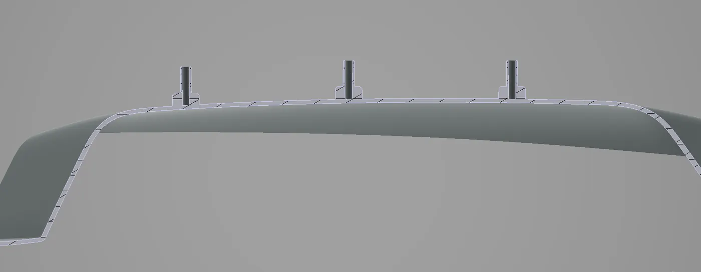
- RENDERED VIEWS
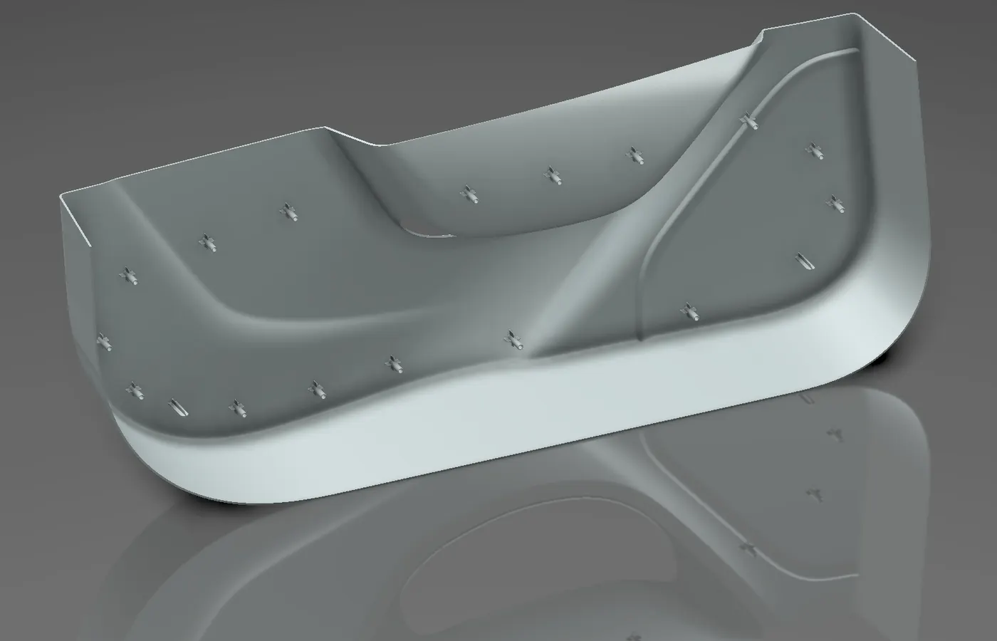
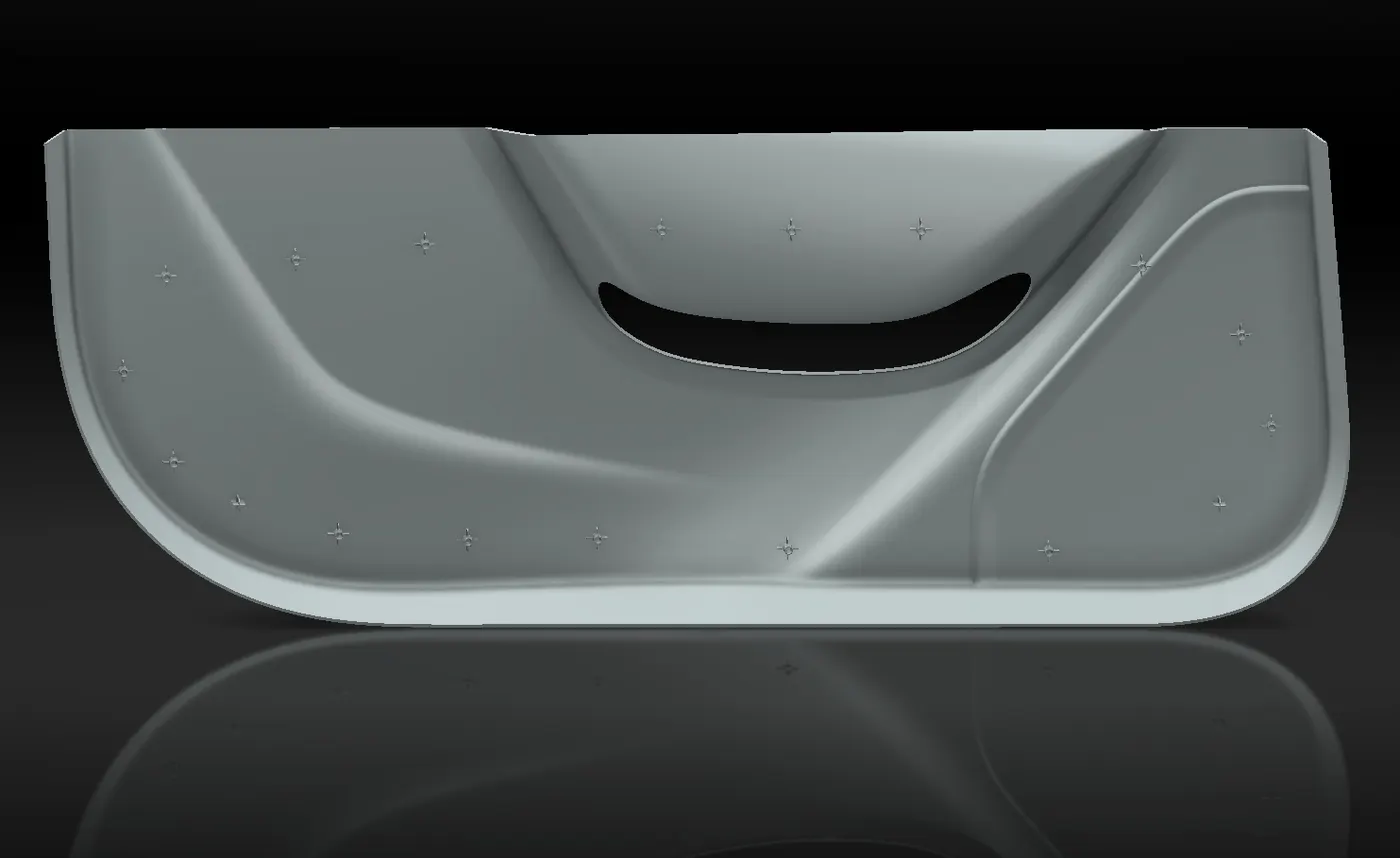
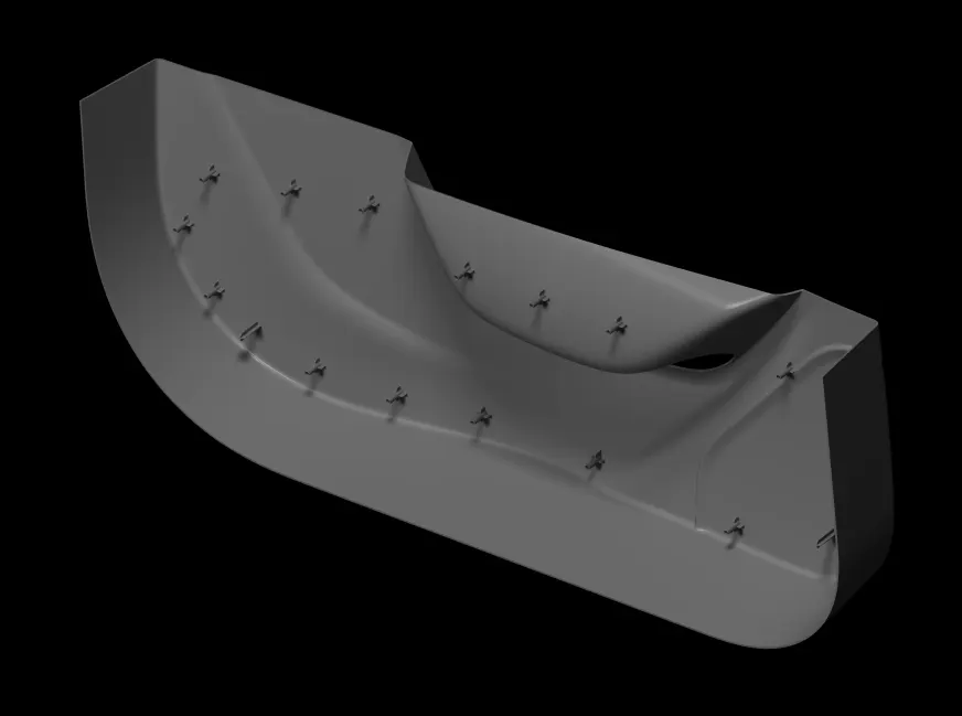
-
- ---------------------------------------END-----------------------------------