Week 10 - Challenge 1- Attachment Feature Creation (Ribs & Screw Boss)
Week 10 - Challenge 1- Attachment Feature Creation (Ribs & Screw Boss)
- OBJECTIVE:-
- Create the rib for the Drill Handle considering the design rules mentioned
- Create the Screw boss for the Drill Handle considering the design rules mentioned
- ASSUMPTION:-
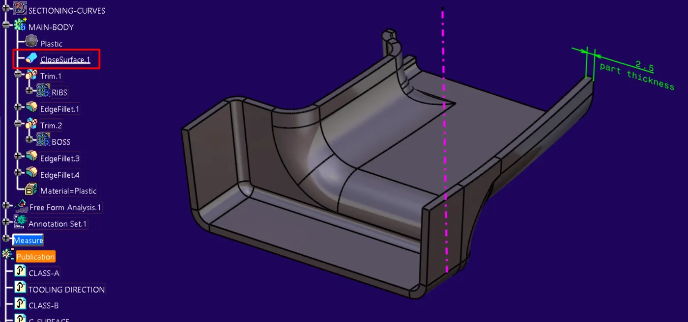
- The thickness of the component is 2.5 mm.
- Component material P.C "polycarbonate".
- ------------------------------------------------------------------------------
- Different views of the MODEL:-
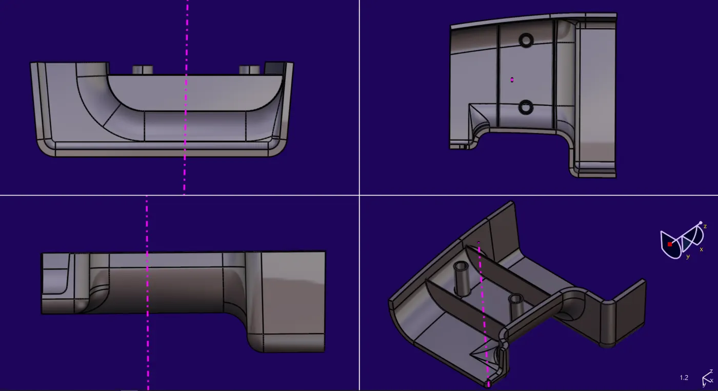
- ------------------------------------------------------------------------------
- Consideration while designing the model:-
-
The distance between each point of the edges of two neighbouring patches must comply with the following limits:
-
For class A: no more than 10 µm = 0.01 mm
-
For class B: no more than 20 µm.= 0.02 mm
-
For class C: no more than 50 µm.= 0.05 mm
-
The angle between the tangents to the surface on the edges of two neighbouring patches must comply with the following limits:
-
For class A: no more than 6’ = (0.1◦).
-
For class B: no more than 12’ = (0.2◦).
-
For class C: no more than 30’ = (0.5◦).
-
(Note:- ( ’) _means minute:- (ex. conversion of minute to degree: - 6’ = 6/60 = 0.1 degree)
-
------------------------------------------------------------------------------
- Expanded tree view with model construction steps:-
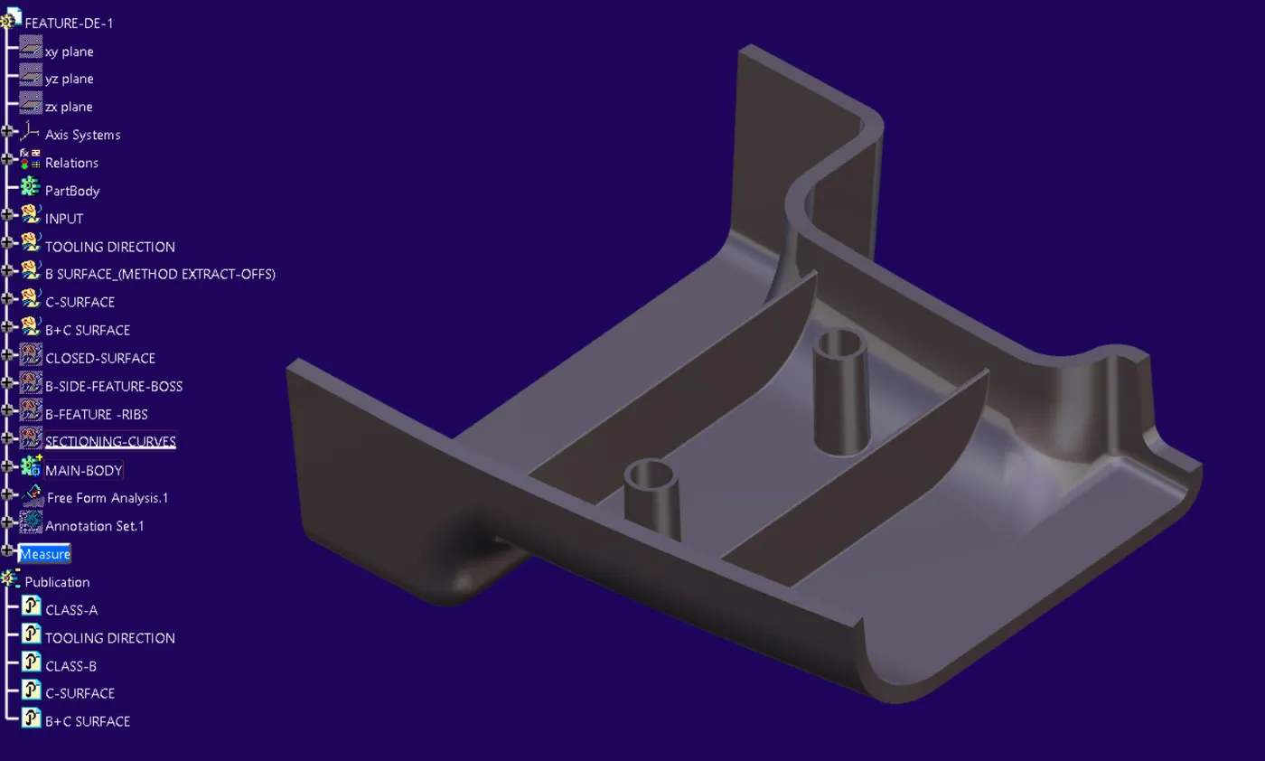
- CLASS-A SURFACE INPUT AND BOUNDARY CHECK
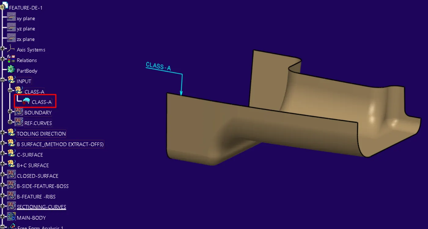
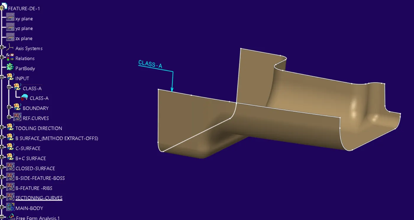
- TOOLING AXIS.
- DEFINITION:-
- Tooling axis:- “ main tool axis” is the axis that defines the mould opening direction.
- The tooling axis must be created on a feature like a hole, slot, cut-out, flat surface, or continuous surface of a Class A Surface.
- The tooling axis justifies the angle sector of the side wall draft ”C-surface”, that is the positive angle of the C surface in the direction of the ejection, “i.e. it creates a relation of the component from mold opening to the ejection of part”.
- The tooling axis must be created in such a manner that gives the ejection clearance and mold opening clearance such no undercut will come in the way during ejection and mold opening,
- it also provides the reference axis to the slider axis or angled pin axis, which is used for the undercut inserts, (known as the undercut at an angle of tool axis),
- While designing mould tools, it is practised that the ejection pins - straight action form pins must be constrained to move parallel to the tooling axis.
- Straight action form pin these pins are ejection pins used to release the Internal undercuts”,
- similarly, sliders are used to remove the external undercut.
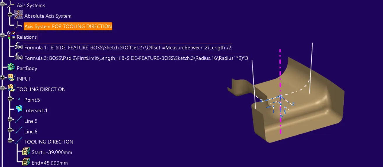
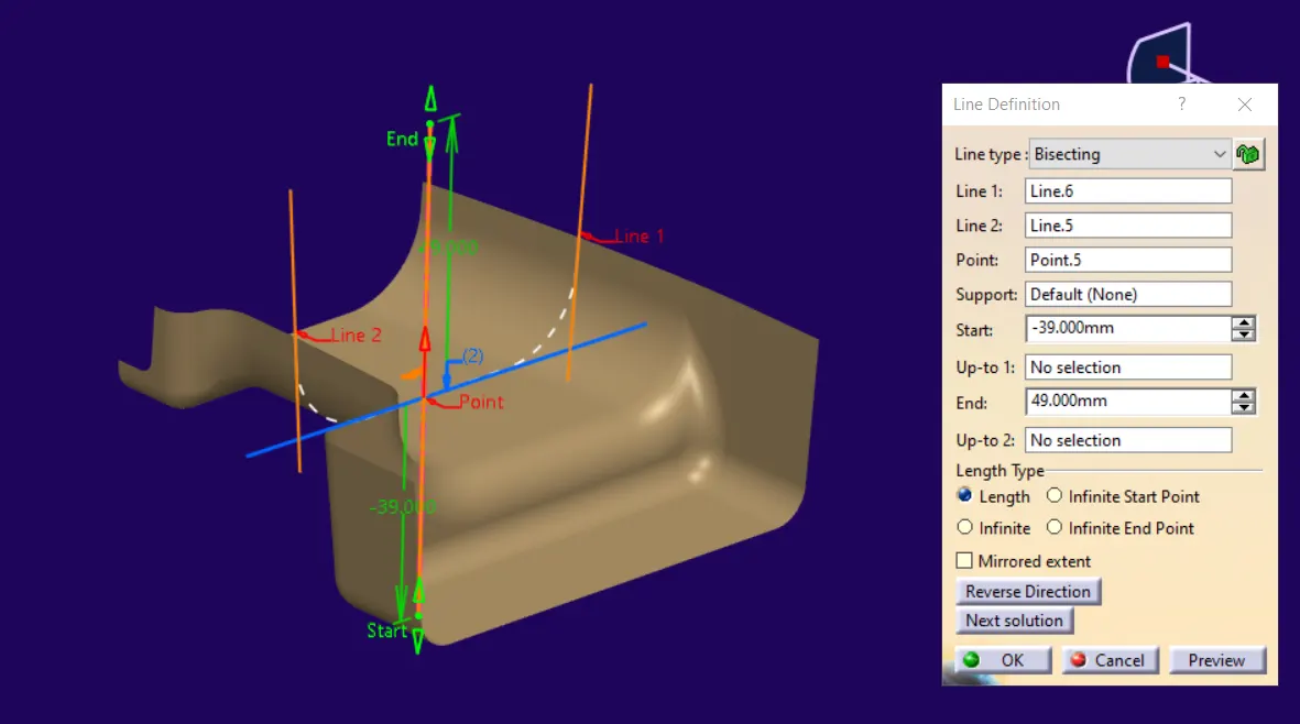
- METHODOLOGY:- " BISECTION METHOD"
- Creating an axis system by taking point on a surface of the base in class A surface which is a flat surface
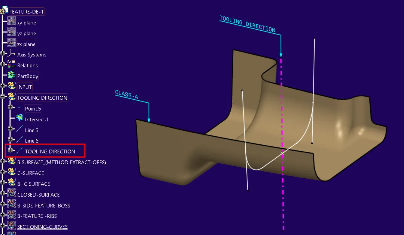
- creating main tool axis "TOOLING DIRECTION" by BISECTING LINE (i.e bisection of the line created from the intersection)
- As shown in images below
- ------------------------------------------------------------------------------
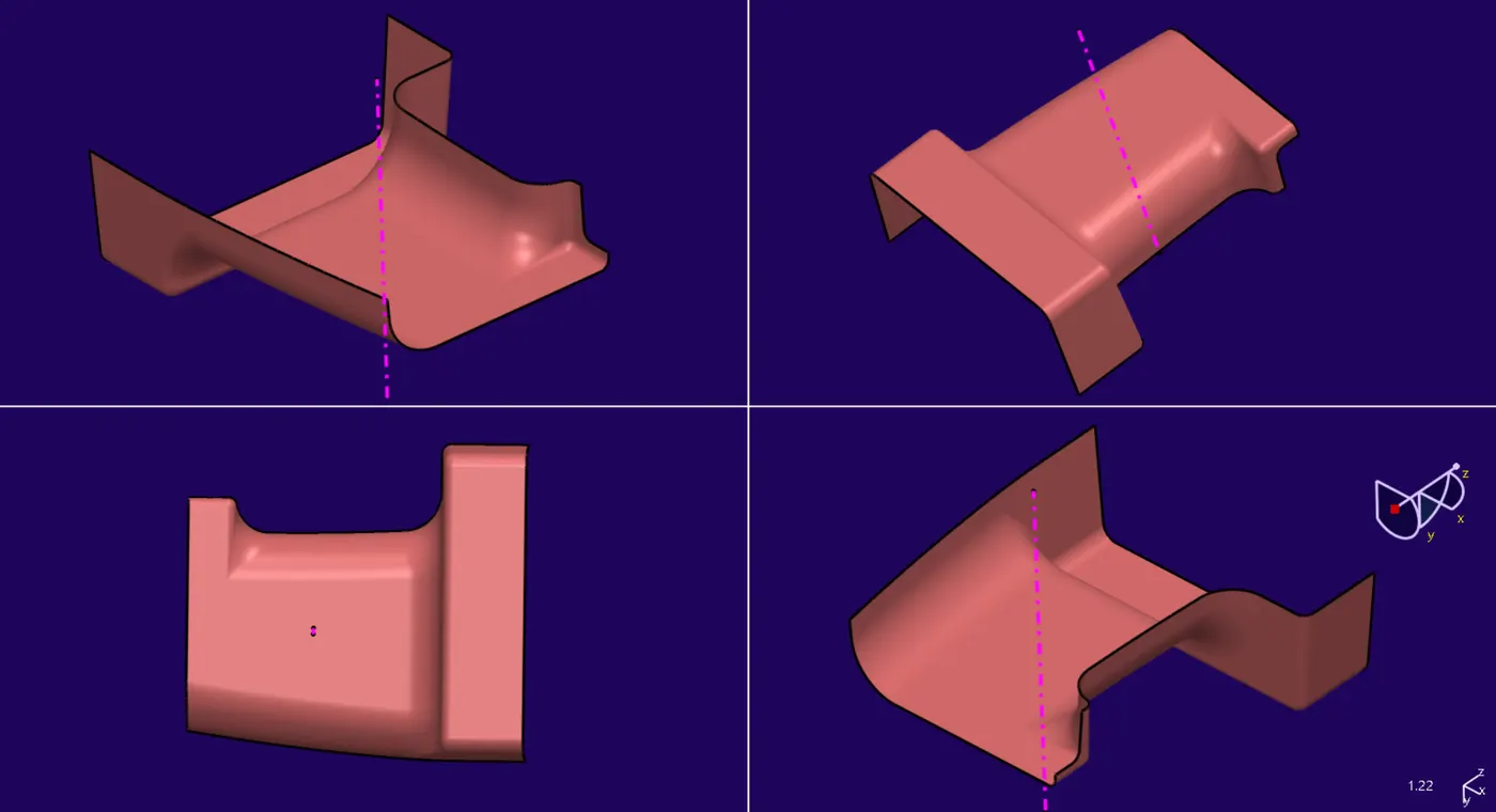
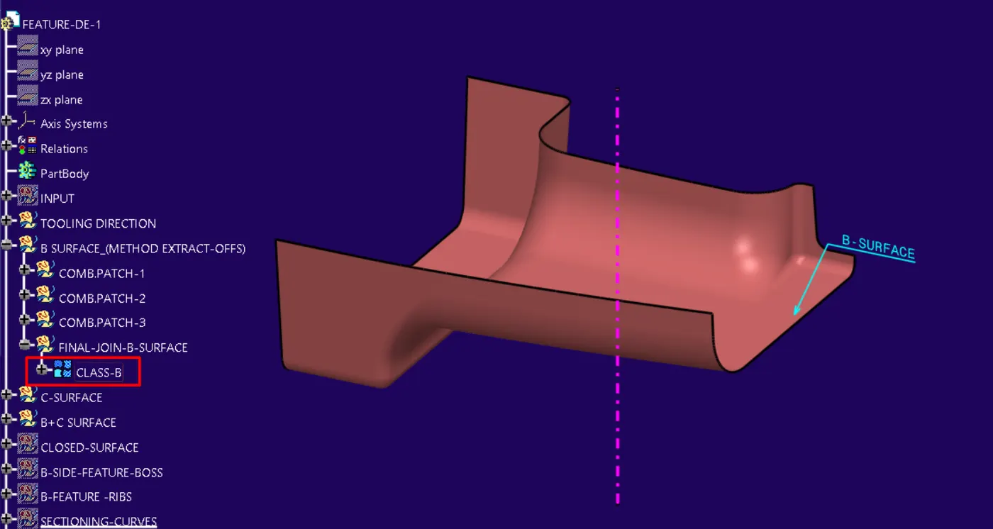
- B-SURFACE "DIFFERENT VIEWS" (view mode_shading with edges without smooth edges)
- FINAL B-SURFACE
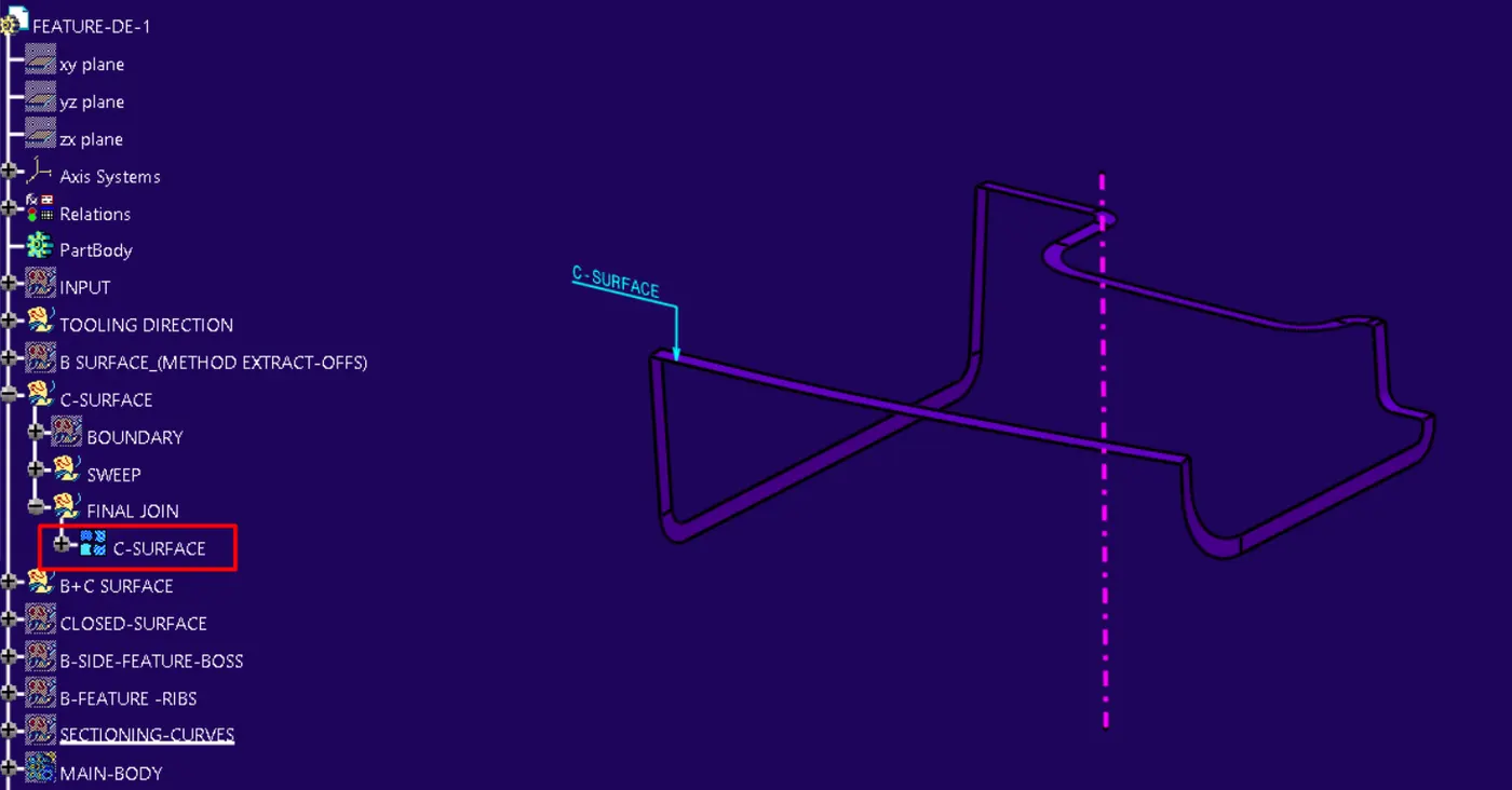
- C-SURFACE
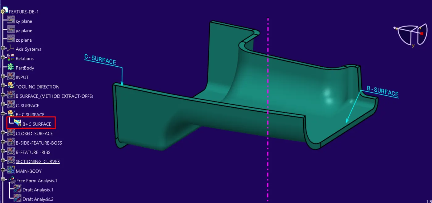
- B+C SURFACE
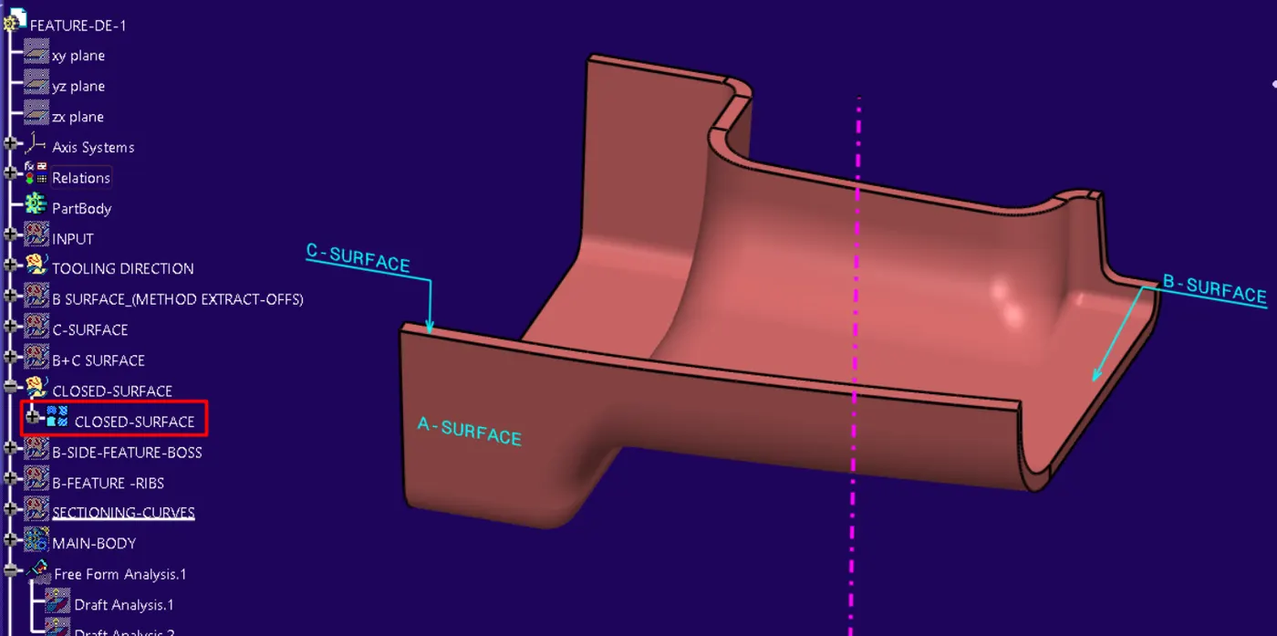
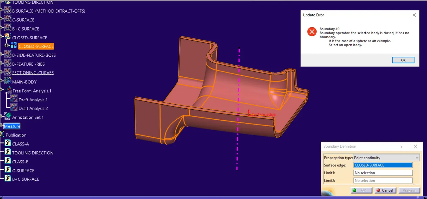
- CLOSED-SURFACE
- CLOSED-SURFACE-BOUNDARY CHECK
- SOLID BODY:- from a closed surface
- ------------------------------------------------------------------------------
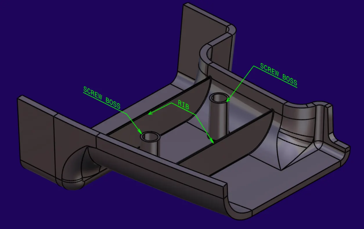
- B-SIDE FEATURE " RIBS AND BOSS"
- DEFINITION:-
- RIBS:-
- Ribs provide a means to economically augment stiffness and strength in moulded parts without increasing overall wall thickness. Other uses for ribs include:
- Locating and captivating components of an assembly;
- Providing alignment in mating parts
- Acting as stops or guides for mechanisms.
- Ribs usually project from the main wall in the mould-opening direction and are formed in blind holes in the mould steel. To facilitate part ejection from the mould, ribs generally require at least one-half degree of draft per side
- More than one degree of draft per side can lead to excessive rib thickness reduction and filling problems in tall ribs.
- Because of the required draft for ejection, the tops of tall ribs may become too thin to fill easily.
- Additionally, very tall ribs are prone to buckling under load.
- If encounter one of these conditions, consider designing two or more shorter, thinner ribs to provide the same support with improved moldability
- Maintain enough space between ribs for adequate mould cooling: for short ribs allow at least two times the wall thickness.
- BOSS:-
- Bosses are used in many part designs as points for attachment and assembly.
- The most common variety consists of cylindrical projections with holes designed to receive screws, threaded inserts, or other types of fastening hardware
- Avoid bosses that merge into sidewalls because they can form thick sections that lead to sinking. Instead, position the bosses away from the sidewall, and if needed, use connecting ribs for support
- Normally, the boss hole should extend to the base-wall level, even if the full depth is not needed for assembly.
- Shallower holes can leave thick sections, resulting in sinks or voids.
- Deeper holes reduce the base wall thickness, leading to filling problems, knit lines, or surface blemishes.
- The goal is to maintain a uniform thickness in the attachment wall
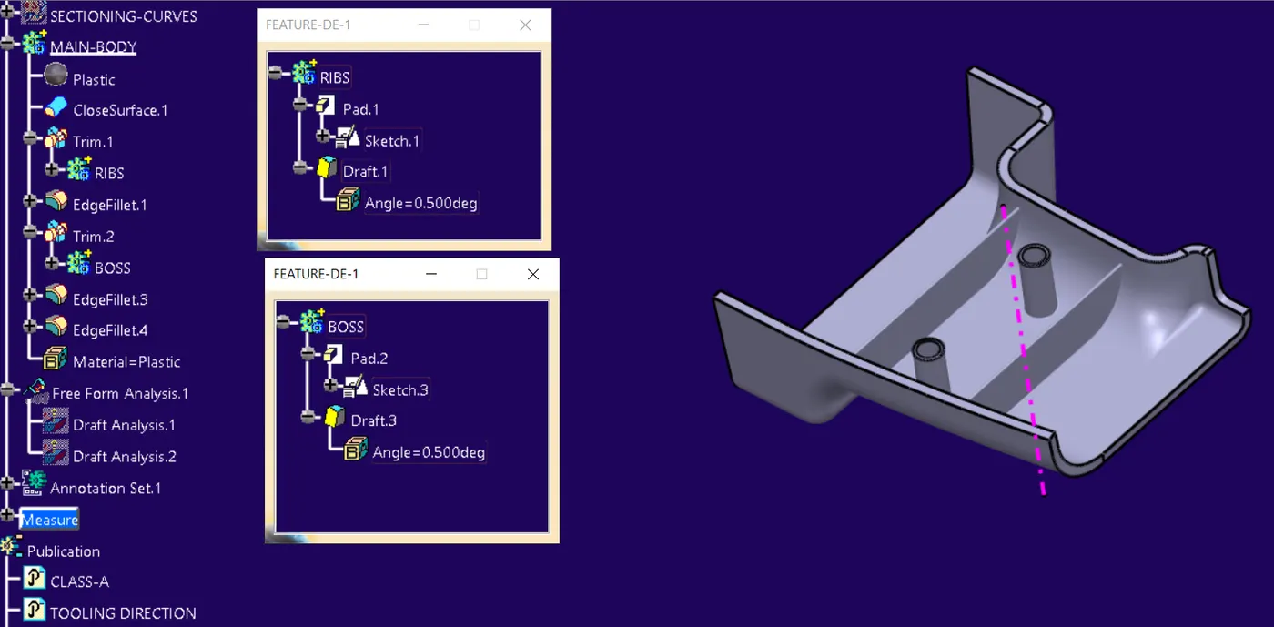
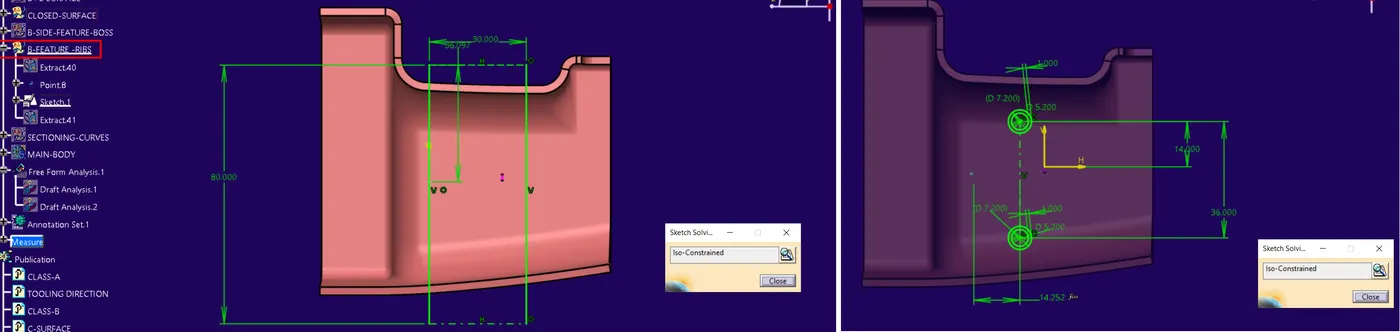
- SKETCHES:-
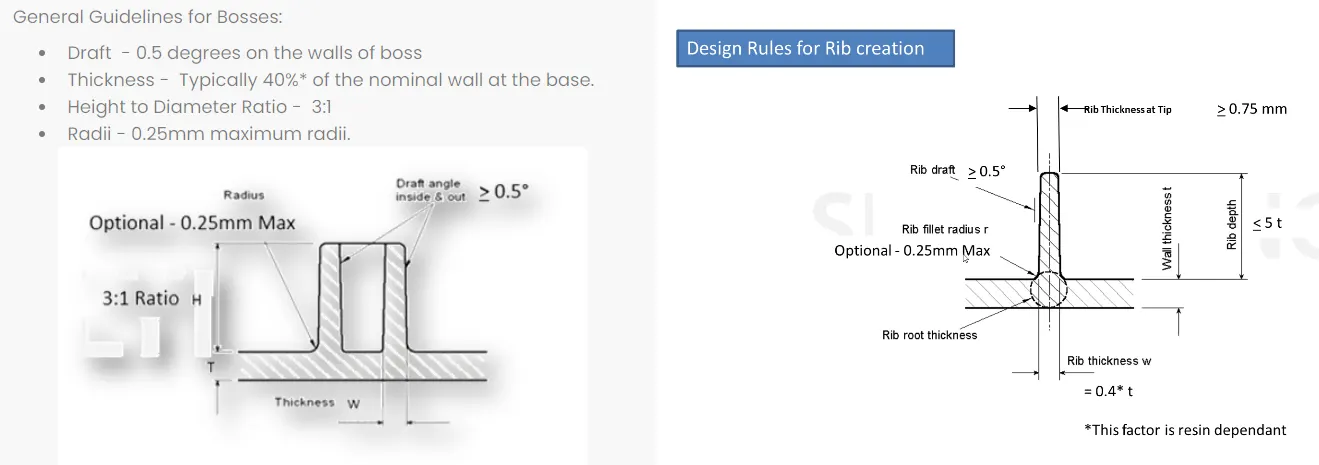
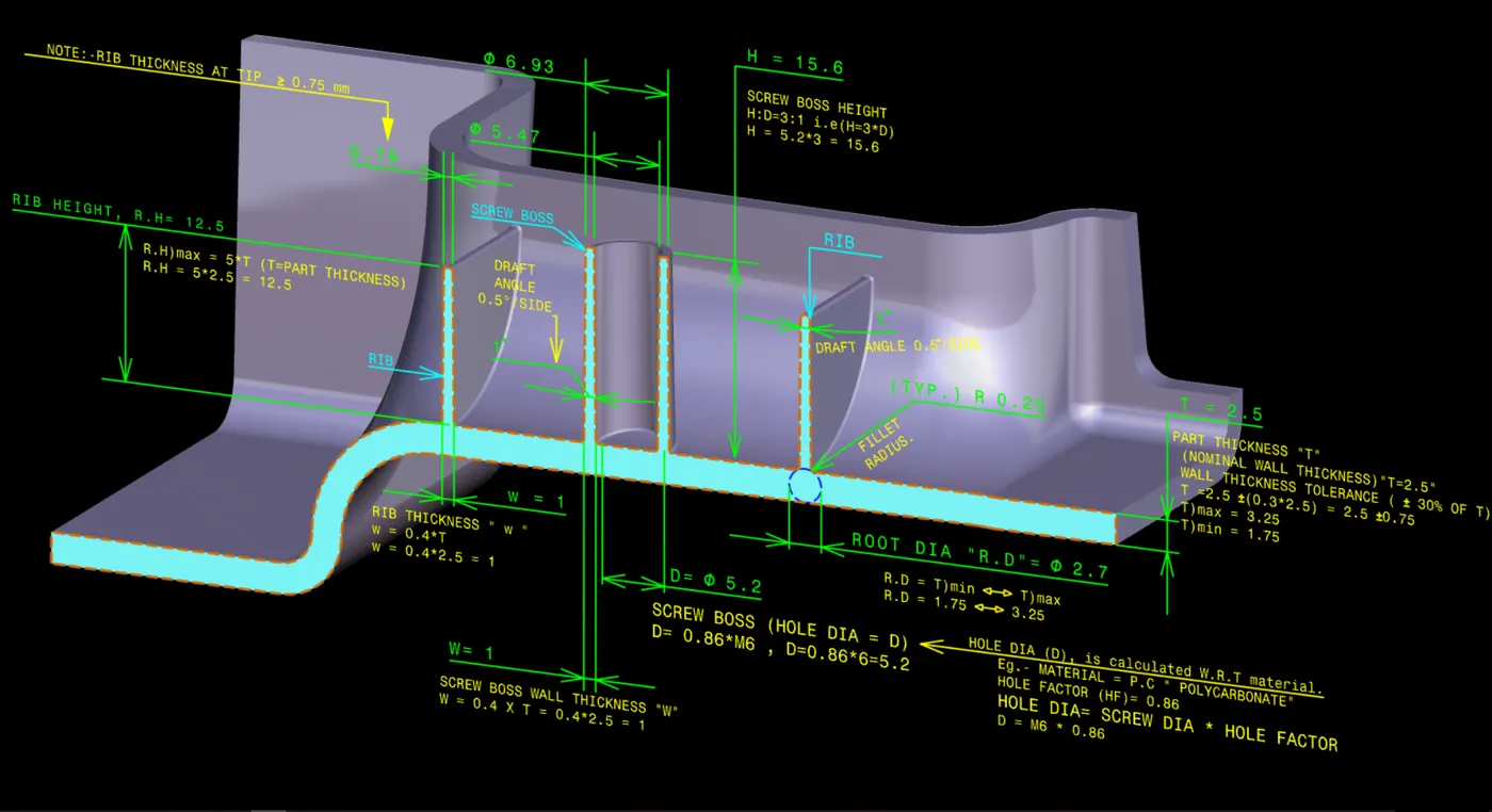
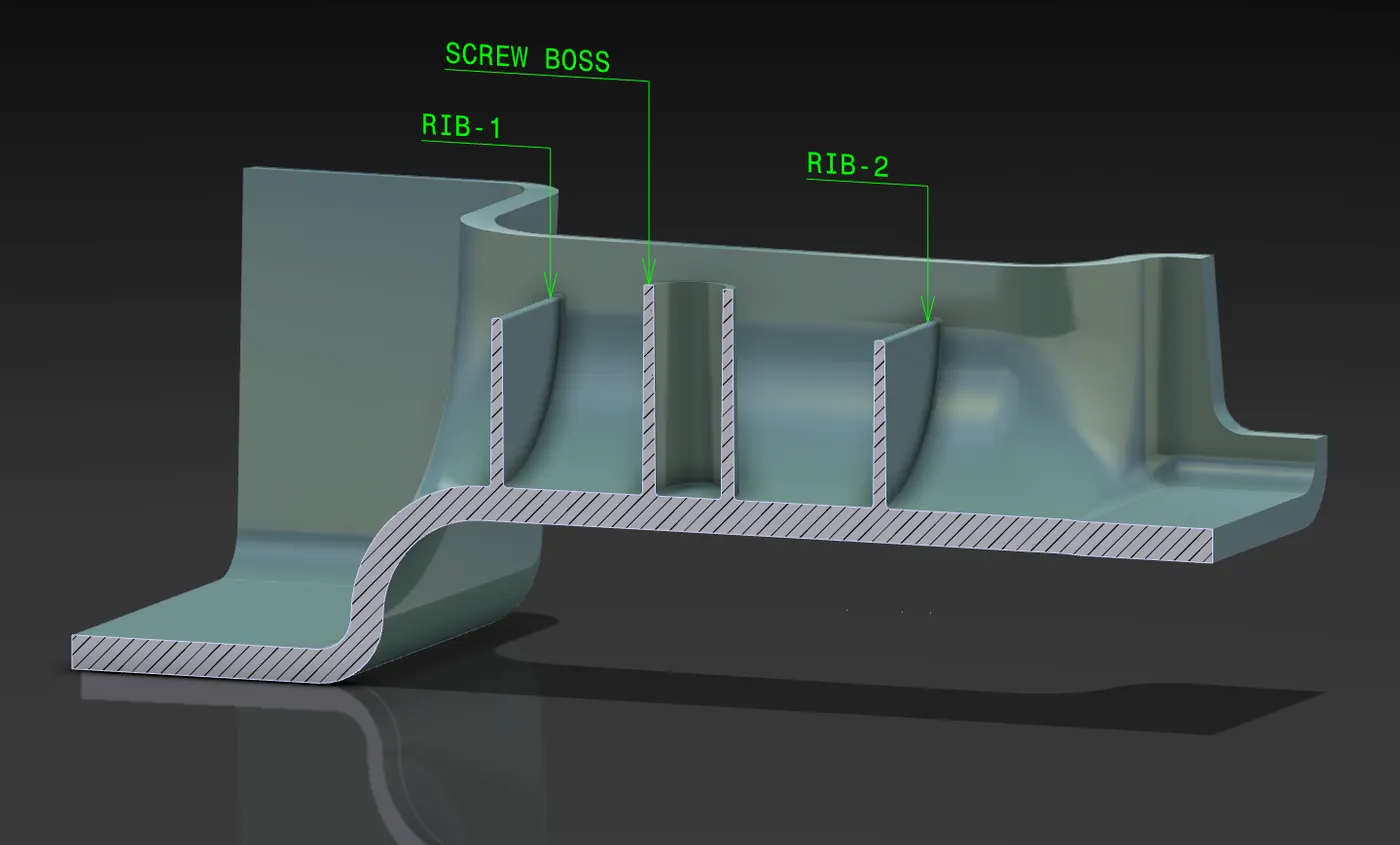
- DESIGN GUIDELINES FOR RIBS AND SCREW BOSS
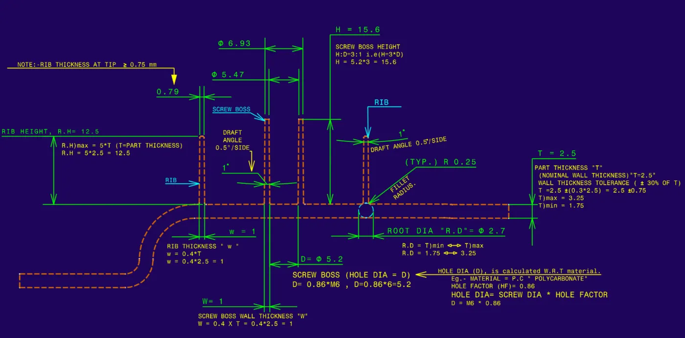
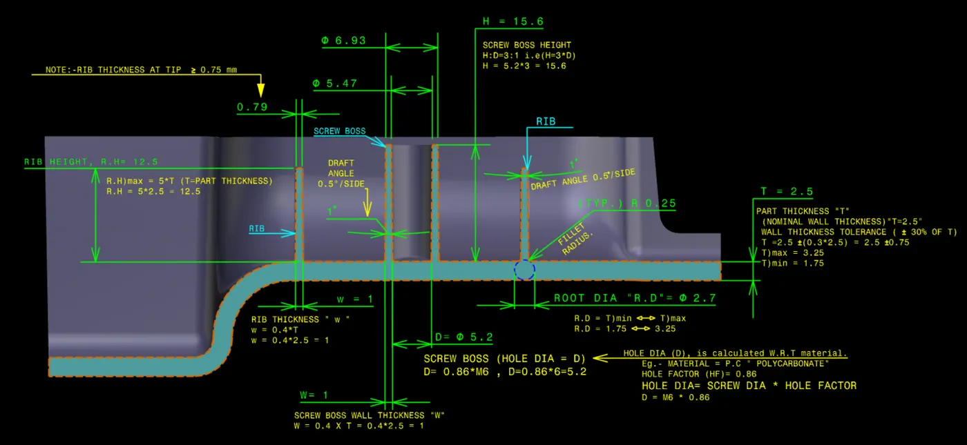
- SECTIONING, DIMENSIONING & DESIGN CHECK "Shown in images below"
- (NOTE:- All dimensions are in mm)
- ------------------------------------------------------------------------------
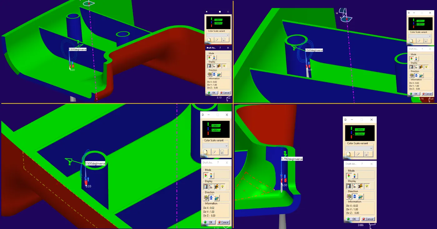
- DRAFT ANALYSIS:-
- DEFINITION:-
- The Draft Analysis enables you to detect if the part drafted will be easily removed “EJECTED”
- The analysis is performed based on colour ranges identifying zones on the analyzed element where the deviation from the draft direction at any point, corresponds to specified values”
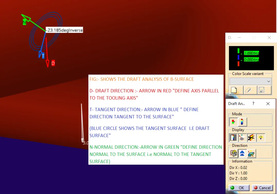
- DRAFT ANALYSIS COMPASS:-Terminology
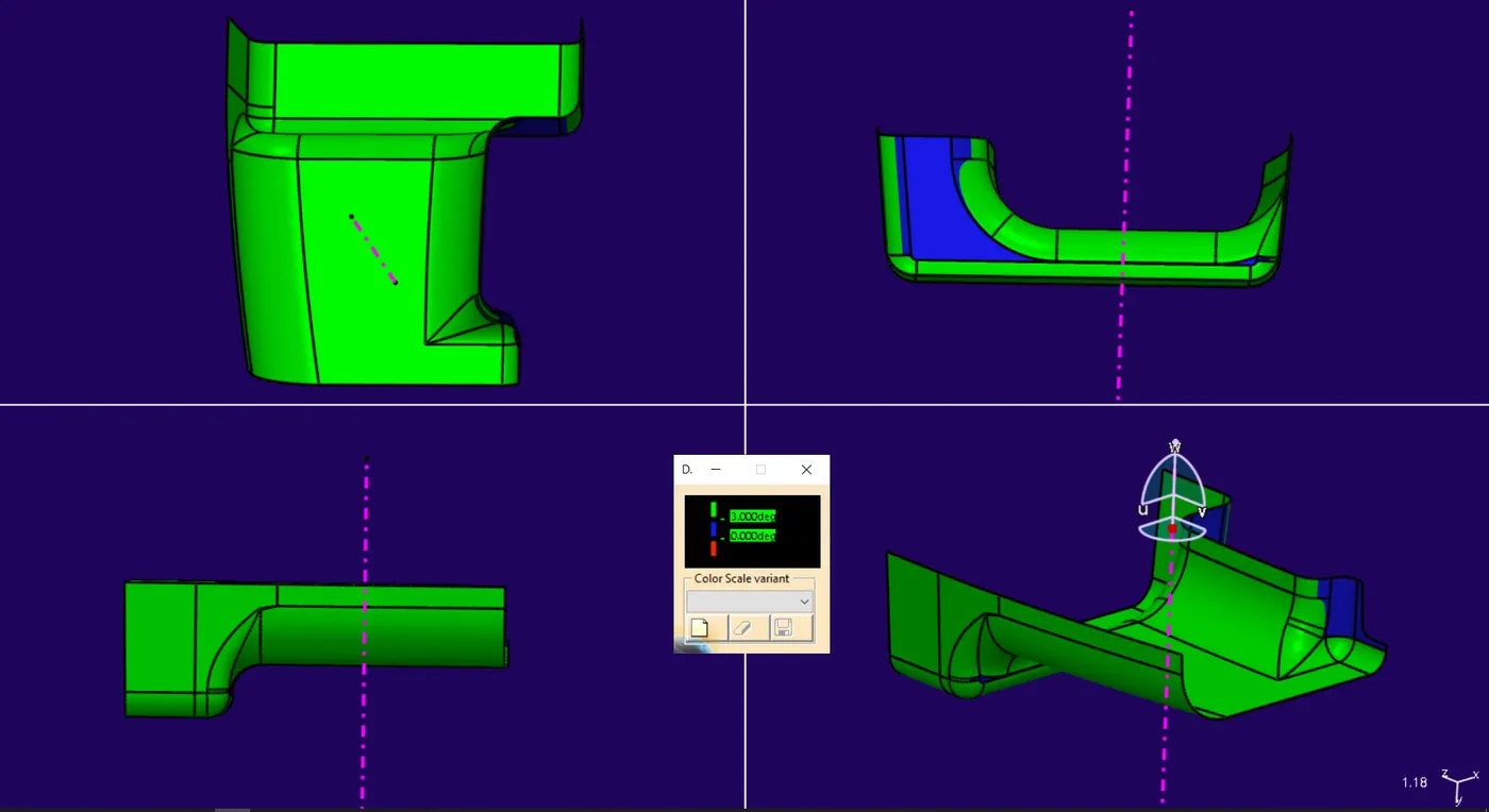
- DRAFT ANALYSIS OF CLASS A SURFACE.
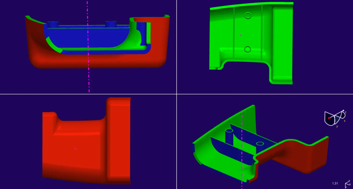
- DRAFT ANALYSIS OF SOLID BODY.
- ------------------------------------------------------------------------------
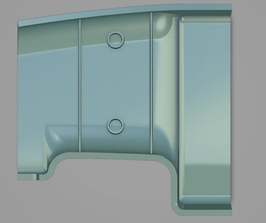
- RENDERED SECTION VIEW
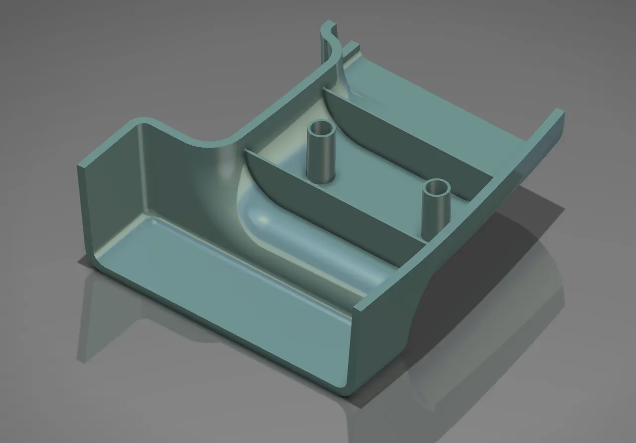
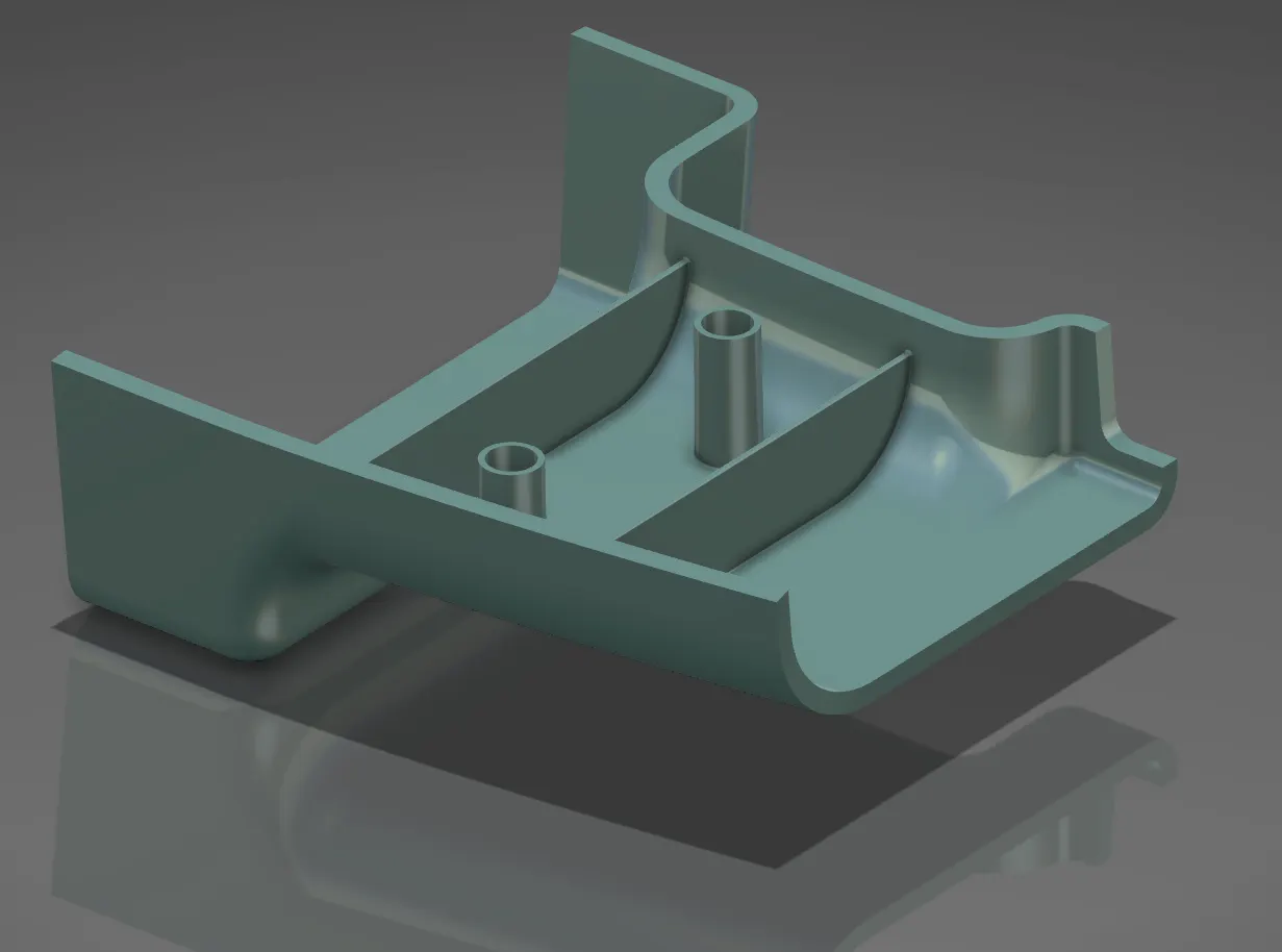
- RENDERED VIEWS
- ---------------------------------------END-----------------------------------