Stress Concentration effect studied on a Plate with hole
AIM-:
ANALYSIS OF A PLATE WITH A CIRCULAR HOLE BY FEM
Theory
Problem Defination
This problems deals with, a plate with a circular hole subjected to a point load σ0=500N.Determine the stress concentration factor through FEA by using ANSYS pre-processor and solver.
FINITE ELEMENT ANALYSIS
Static Stress and Strain Concentration Factors:
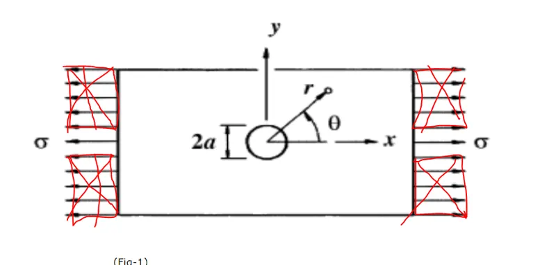
(Fig-1)
Static Stress and Strain Concentration Factors Consider the plate shown in Fig.1, loaded in tension by a force per unit area, σ. Although not drawn to scale, consider that the outer dimensions of the plate are infinite compared with the diameter of the hole `2alpha`. It can be shown, from linear elasticity that the tangential stress throughout the plate is given by,

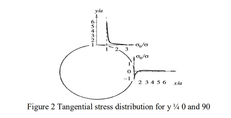
The maximum stress is σϴ=3σ at r = a and `theta`= `90 degree` Figure.2.shows how the tangential stress varies along the x and y axes of the plate. For the top (and bottom) of the hole, we see the stress gradient is extremely large compared with the nominal stress, and hence the term stress concentration applies. Along the surface of the hole, the tangential stress is -σ at `theta`= 0degree and 180 degree , and increases, as `theta`increases, to 3σ at `theta`=90 degree and 270 degree
The static stress concentration factor in the elastic range, `K_t`, is defined as the ratio of the maximum stress,`sigma_max`, to the nominal stress, `sigma_(nom`, That is,
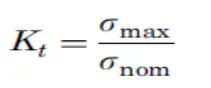
For the infinite plate containing a hole and loaded in tension, `sigma_(nom` =σ, `sigma_max` = 3σ, and thus `k_t` = 3.
The analysis of the plate in tension with a hole just given is for a very wide plate (infinite in the limit). As the width of the plate decreases, the maximum stress becomes less than three times the nominal stress at the zone
containing the hole.
Figure 3(a) shows a plate of thickness t = 30mm in, width D =120 in, with a hole of diameter 2r =60 in, and an applied uniform load = 500N
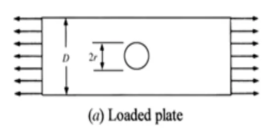
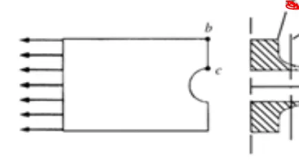
Fig-3
FEA CASE SET-UP
Stress concentration on a plate with hole
Case 1
The task for this case is to design a rectangular plate with a hole in the middle of 60mm diameter and an increased thickness and perform static structural analysis using ANSYS Workbench. The material used is Structural Steel and shown below is the sketch of the plate designed using ANSYS SpaceClaim.
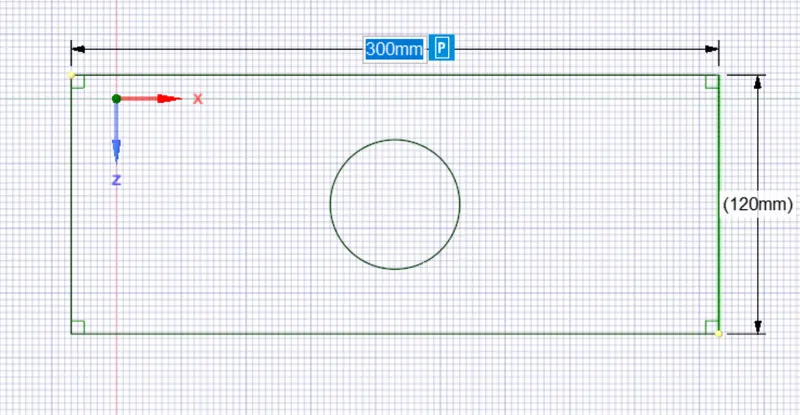
Following are the dimensions of the plate:
Length 300mm
Height 120mm
Thickness 30m
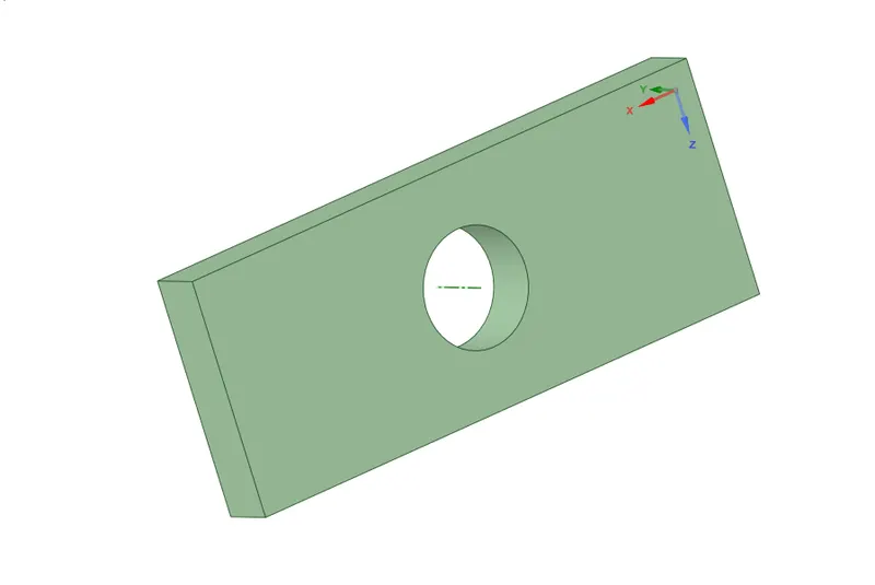
The 2D geometry sketch is then extruded in SpaceClaim as shown below and this 3D model then can be imported into ANSYS Mechanical for the structural analysis.
The properties of the Structural Steel Material are as follows:
Density 7850 kg m^-3
Isotropic Secant Coeff’ 1.2E-05 C^-1
of Thermal Expansion
Young’s Modulus 2E+05 MPa
Poisson’s ratio 0.3
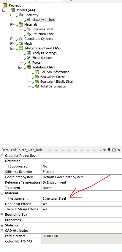
The next step is meshing the model. Since the Required material is Structural Steel, the default material has not been changed.
The assigned material is structural steel
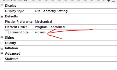
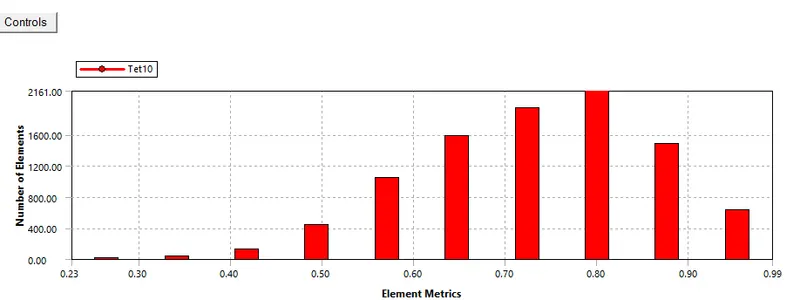
Since ANSYS Student version is being used, the appropriate element size was finalized by iteration. 6.5mm element size was finalized as it does not exceed the allowable nodes and elements. The mesh metric is utilized to identify the elements according to their quality. The quality of the mesh is acceptable as most of the elements lie within high quality range of 0.7- 0.9.
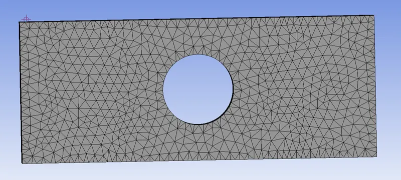
The patch conforming method with tetrahedrons is utilized for the meshing and no other default settings has been changed. The meshed model for the plate is as follows:
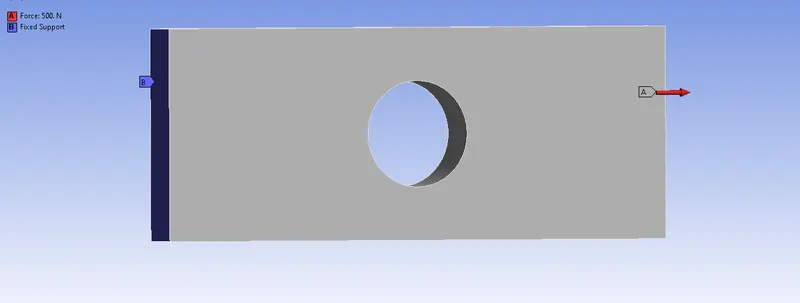
Now for the boundary conditions, a fixed support on side of the plate is applied and a tensile load of 500N is applied on the opposite side as shown in the picture below.
Case 2
For this case, the plate with similar dimensions is modified and 2 holes of 30mm diameter and 90mm away from the center on either side of the big hole are added. The material remains the same for this case as well. The model for this case is as shown below.
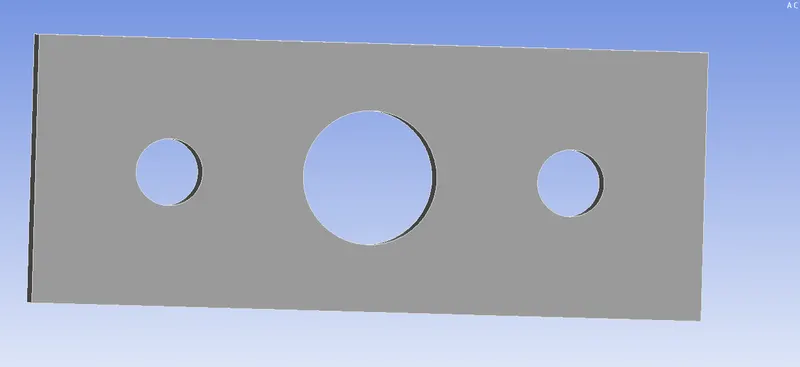
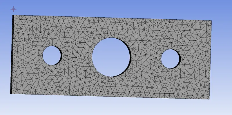
For the meshing, the patch conforming method with tetrahedrons is applied, and an element size of 4 mm is used.
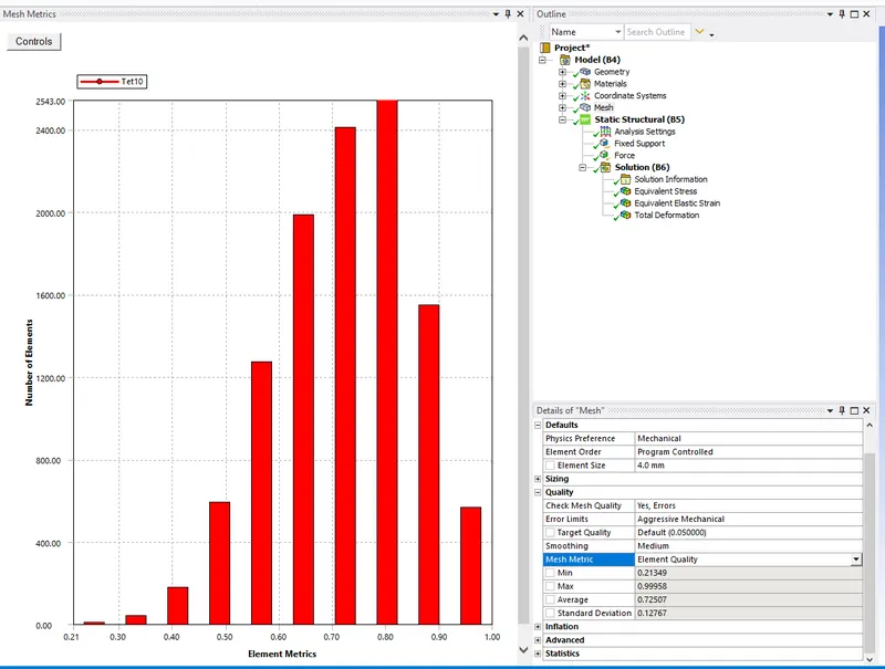
To check the quality of the mesh, mesh metric is applied that identifies the quality of the elements. Most of the elements fall inthe range of 0.5 -0.9, therefore the quality of the mesh is acceptable. The meshed model is as shown below.
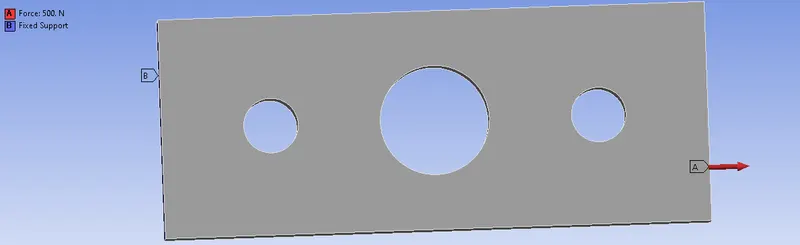
The next step is to apply the boundary conditions in the similar way as in the first case. A fixed support is applied on the one side and a tensile load of 500N is applied on the other as shown below.
Results
After solving the model, the following results are obtained.
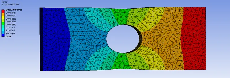
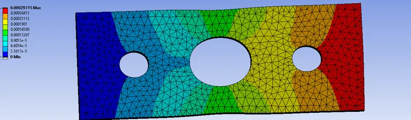
The Total Deformation Results for both the cases Case 1 Case 2
Min Deformation (mm) 0 0
Max Deformation (mm) 2.7484e-004 2.9715e-004
Avg. Deformation (mm) 1.3679e-004 1.45e-004
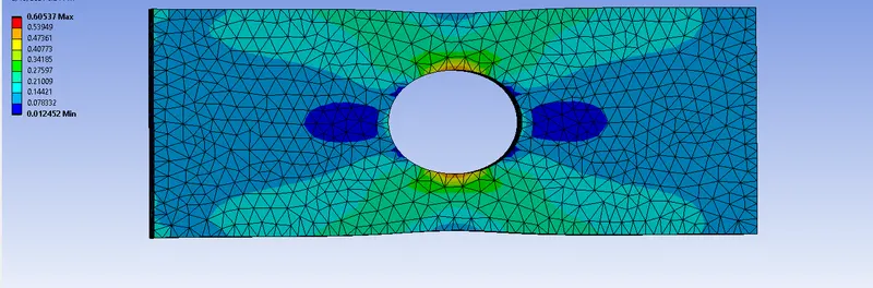
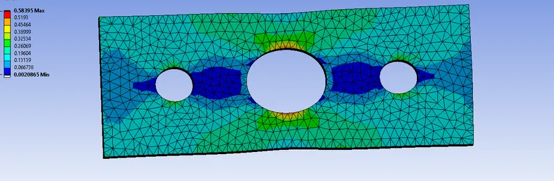
The Equivalent Von-Mises Stress for both the cases
Case 1 Case 2
1.2452e-002
Min Equivalent Stress (MPa) 1.2452e-002 2.0865e-003
Max Equivalent Stress (MPa) 0.60537 0.58395
Avg. Equivalent Stress (MPa) 0.16907 0.16806
Total deformation for Case 1
Total Deformation for Case 2
Equivalent Von-Mises Stress for Case 1
Equivalent Von Mises Stress for Case 2
Conclusion
2. On comparing the Total Deformation for both the cases, there is only a slight change in the values with only the Avg. Value is evident. The case 2 has greater values and the Max Deformation for the Case 2 is only bigger by the order of 0.23 mm.
3. The reason Case 2 has higher Deformation than Case 1, because the reduction in material in Case 2 reduced the stiffness of the
plate.
4. On comparing the Equivalent Stress results, the sudden change in the geometry causes a stress concentration around the holes. Case 2 has lower Max Stress as compared to Case 1 because the extra 2 holes in Case 2 evenly spreads the stress and stress concentration. With the use of adequate holes, stress concentration can be further reduced. Case 1 has 0.598 MPa of Max stress around the hole and is greater than Case 2 Max stress by 0.021 MPa.
5. It is also observed that Case 1 has higher Min Stress compared to Case 2, as stress concentration is distributed in Case 2 due to holes.
6. From an analysis standpoint, Case 2 design must be used as it reduces the stress concentration around a single hole. Case 2
design will have a longer operational life and Case 1 design may fail early due to stress concentration.
7. From a Manufacturing standpoint, Case 1 design shall be used as less manufacturing operations are involved which will also
prevent material wastage and associated costs. Besides, there is no significant difference in both the designs.