INNER AND OUTER HOOD MESHING USING HYPERMESH FOR CRASH ANALYSIS
Model- Hood
Aim- 2D meshing of sheet metal
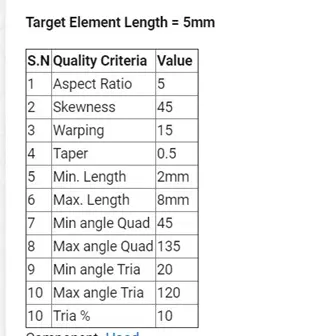
Quality criteria
Procedure
- As the given geometry is in .stp file , import it through import geometry tool
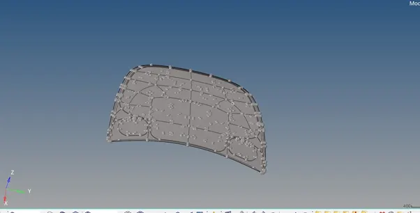
- Turn on topo mode from tool bar.
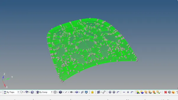
3. As it’s showing green, It evidence that there is solid inside it. So we have to delete solid as we have to work on midsurface only (2D shell element).
Delete>select solid>displayed>delete
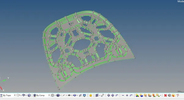
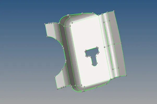
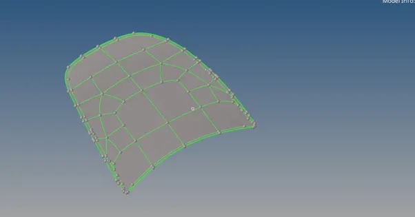
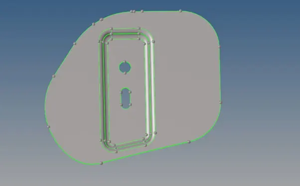
3. Extract midsurface
Geometry>midsurface>select component(from tab area)>displayed>extract
a. Turn on surface you want work on from feature tree, right click and select make as current
b. Delete symmetric part.
C. Do the geometry clean upd,Split the surface as rectangle, pentagon and triangle where ever it’s possible.
d. Untoggle unwanted construction line
e. Also untoggle construction line if element is failing for minimum lengthg.
f. Apply preference and quality criteria
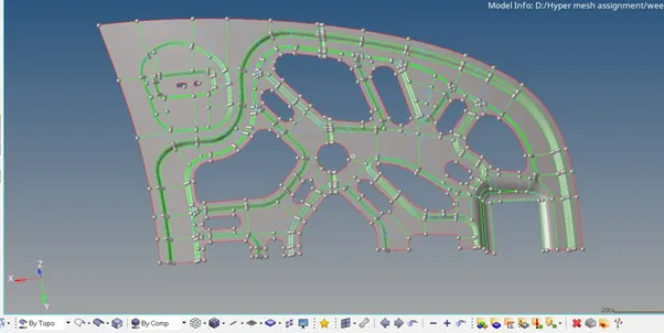
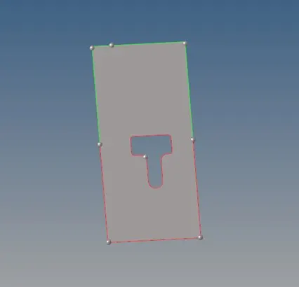
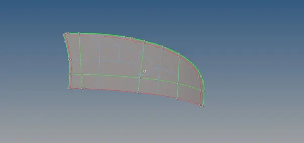
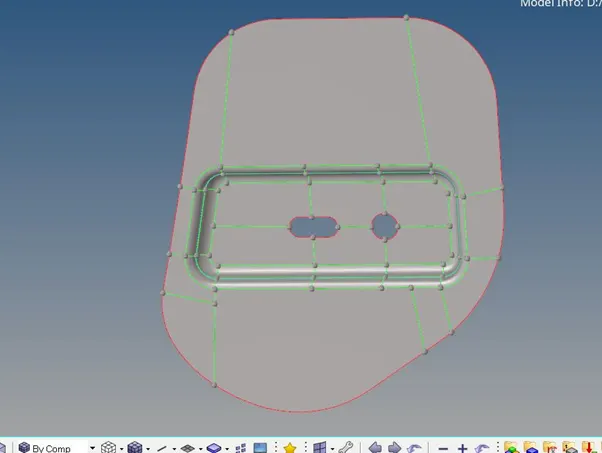
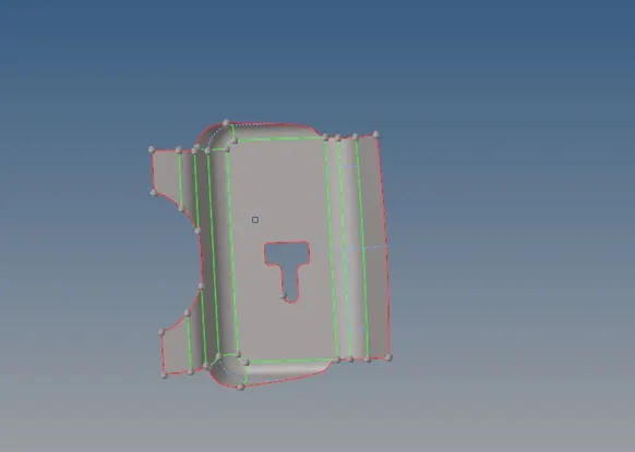
4. Strat meshing from complex geometry as it is hard to capture as per quality criteria
F10>SELECT SURFACE> TARGET LENGTH>ELEMENT TYPE>ELEMENT ORDER>MESH
5.Increse or decrese mesh density for proper mesh flow. Also select bias and chose geometry type and remesh again, if it gives better mesh flow.
6.Do the mesh each splitted region individually. Remesh again and again to reduce trias as many as possible and as we are working on model for crash analysis, remesh and split the rotating quads to trias if exist.
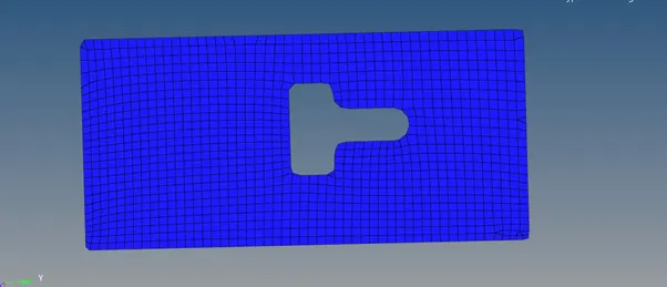
7.There should be even no of elements at hole.
Check element fails ( press f10 from keyboard)
8.If there are warpage comes, break that quad to trias.
2d>edit element>split
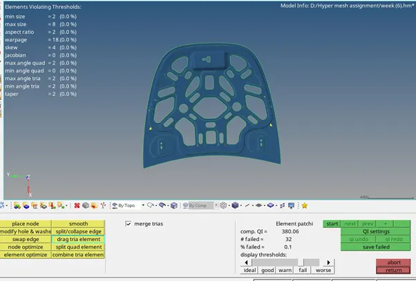
9.Some skew, maximum angle quad and minimum angle quad quality criteria can be corrected by element optimization.
2D>QUALITY INDEX>CLEAN UP TOOL>ELEMENT OPTIMIZE
N.B- USE ELEMENT OPTIMIZATION TOOL AS LESS AS POSIIBLE NEAR FILLET REGION. BECAUSE IT ALLOWS MESH TO DEVIATE FROM FEATURE LINE. USE THE PROJECT BY SELECTING TOOL(FROM MAIN MENU PAGE) TO ALIGN THE NODES ON FEATURE LINE
9. Element failing for minimum and maximum quality criteria can be avoided by
a.converting to tria
2d>replace>select node
b.by increasing distance
geometry>distance>select two node>give distance>left click on graphical area
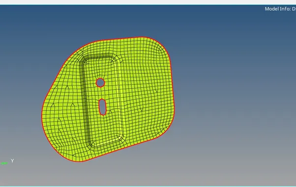
11.The final mesh-
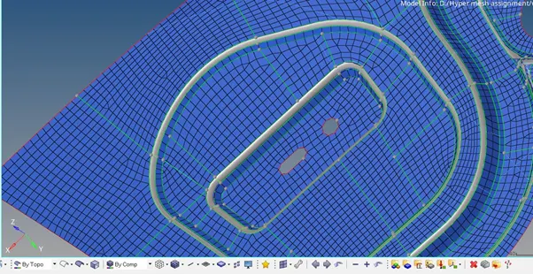
(Feature capture)
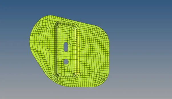
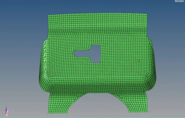
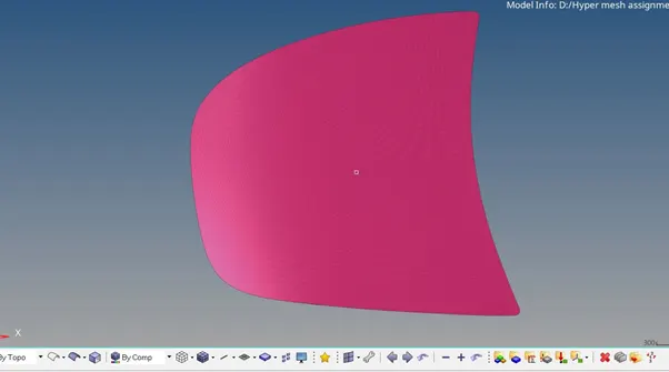

(No rotating quads)
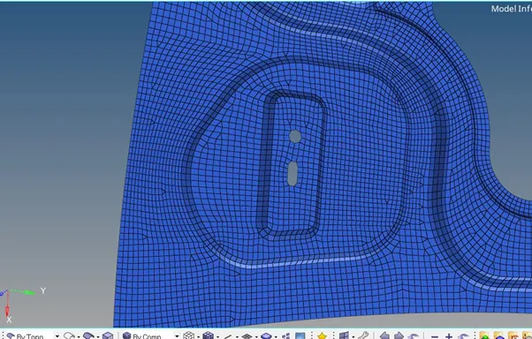
(No back to back and opposite tria)
12.Turn on mid surface geometry from feature tree and check for proper feature capture.
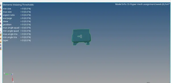
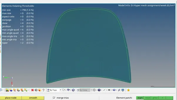
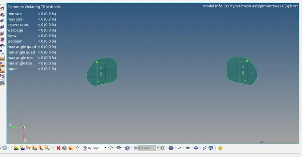
13.Check quality of the element as per quality criteria
2D>quality index
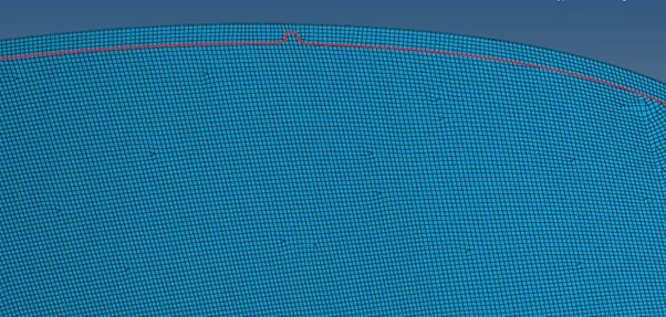
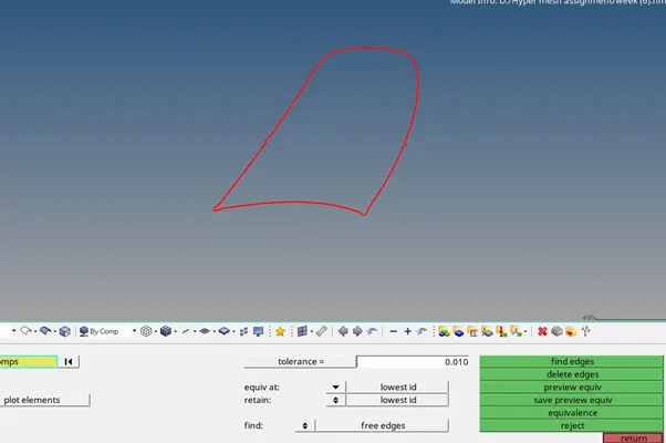
14.Check element connectivity and free edge
Tool>edge>component> find edges
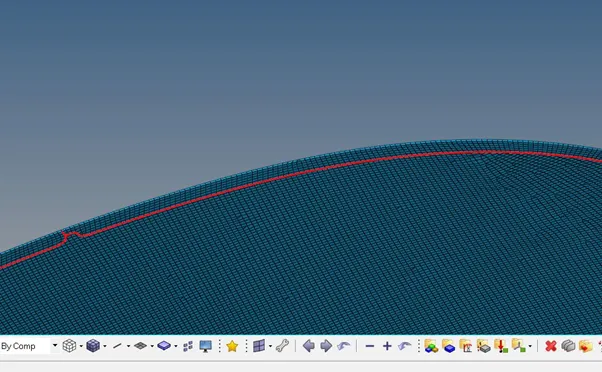
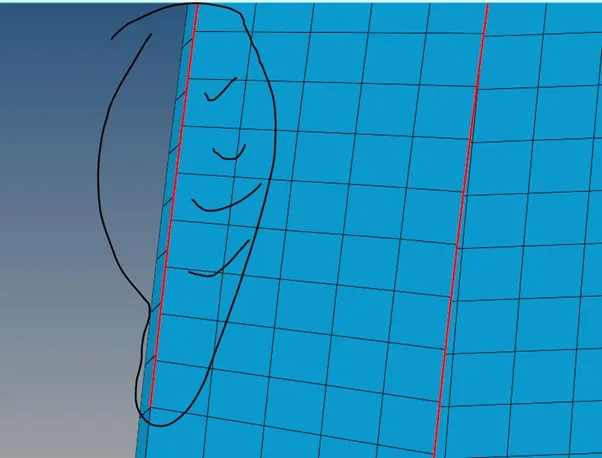
15. To clear the free edeges –
2d>replace>select node
16.Reflect the mesh about symmetric axis.
Tool>reflect>(displayed+duplicate to current component)>select axis>base node>reflect
17. Give equivalence to make connectivity between two symmetrical parts.
Tool>edge>select all displayed elements >preview equivalence>equivalence
18.Check element connectivity and free edge, as we did previously. If exist , Fix those edges by the method we followed previously.
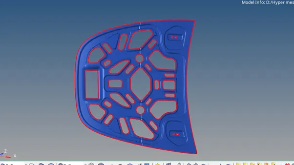
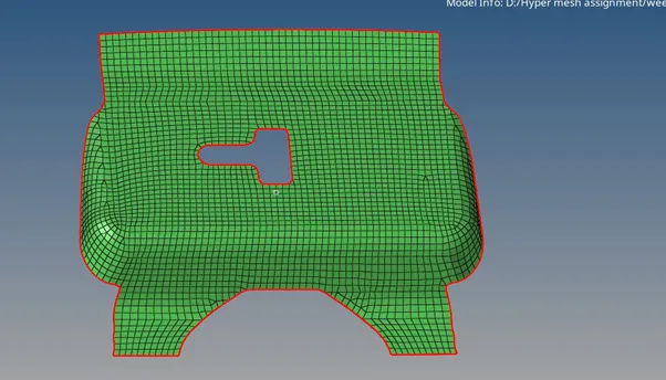
Final model----
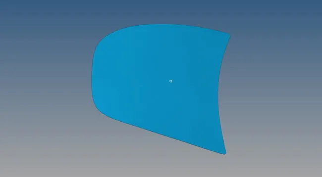
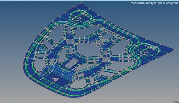
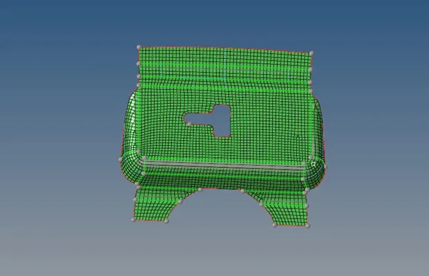
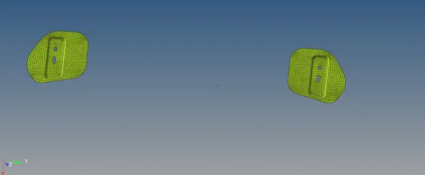
Conclusion-
- Though tria shell elements are not preferred in model that will use for crash analysis, we can not completely avoid tria. To make uniform grid we definitely need trias to keep near complex gemotry (converging-diverging).
- Rotating quad can be breakdown to two trias.
- Splitting the model to uniform geometrical shape like rectangle, pentagon, triangle gives the better mesh flow.
- Remeshing two opposite tria can give quad element. Same problem can resolved through drag tria command but that makes mesh waivy. Always use smooth command after using drag tria command
N.B- Combining two opposite tria that are parallel to each other in two splitted region are not advisable, as it deviates feature line.
- Project command can be use to align the grid points with construction line.
- Starat meshing from complex region like hole and converging-diverging for better flow.