2D meshing of Plastic side door for crash analysis
Model- SIDE DOOR
Aim- : To mesh the given component by extracting mid-surface manually and perform mesh quality checks.
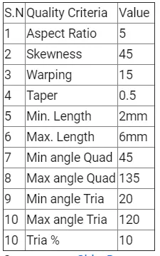
Quality criteria
THEORY
The pre-processing of a plastic model is done by extracting a midsurface. The midsurface is then meshed and assigned appropriate thicknesses in various areas to account for any thickness variation. This mesh is a finite element representation of the original model, which can be used for crash test analysis or stress-strain analysis. The element that can be chosen for the mesh depends on the type of analysis that is to be carried out. We will be using 2D shell Quad and Tria elements, with each node having 5 DOFs, 3 translational and 2 rotational. The reason for using 2D shell elements is that they are ideal for situations where one of the dimensions is much smaller than the other 2. In this case, it is the thickness of the part
Procedure
- Import the model
- Turn on topo mode from tool bar.
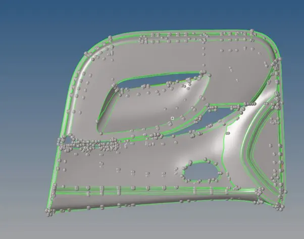
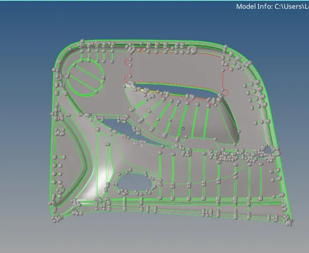
3. Extracting midsurface Manually
A.Turn on surface you want work on from feature tree, right click and select make as current
B. The part consists of a central base which is of 2.8m thickness and the rest of the features are of various thicknesses. The part has some solid features, which are unsuitable for 2D meshing, which is our objective. We will be ignoring these features as well as any feature of thickness more than 6 mm
C .There are a number of strengthening ribs of various dimensions, which we will have to extract accordingly.
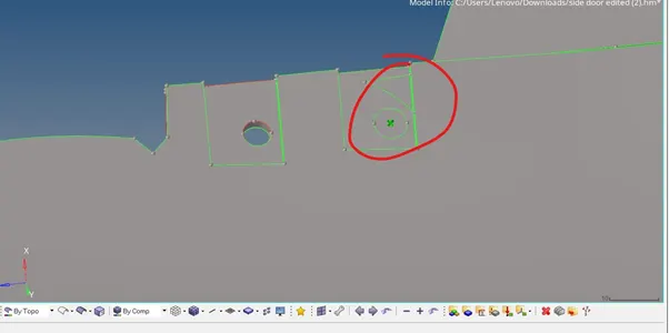
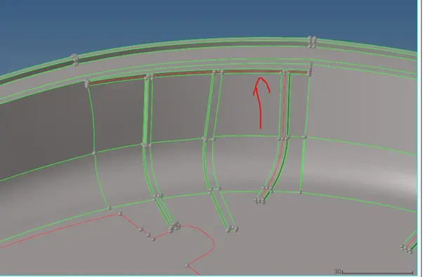
D.There are some geometrical errors, and free edges, which we have to correct before we move on to mid-surface extraction.
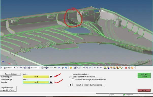
Since the part geometry is fairly complex, we will be extracting mid-surface manually. Using surface offset command, the mid-surface is extracted into a separate collector. The surfaces are offset according to the thickness of the respective parent geometry surface. Regions where thickness is more than 6mm is ignored for the purpose of mid-surface extraction.
Gem>surface edit>offset>surface(duplicate to current compoent)>offset value>offset

After midsurface extraction geometry cleanup is to be performed on it and the results are evaluated to check for any abnormalities.
Operations performed in geometry cleanup:
- Split the surface as rectangle, pentagon and triangle where ever it’s possible.
- Untoggle unwanted construction line
- Also untoggle construction line if element is failing for minimum length
- Apply preference and quality criteria
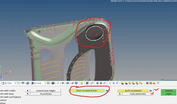
Tools used: Surface edit - Extend, Offset, Trim Quick Edit - Toggle edges, Replace Nodes, Add Nodes, Filler edges Surfaces - By Skin Line edit - Extend lines, Trim With Lines Measure - Two points Tools – Organise
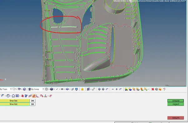
FINAL MIDSURFACE
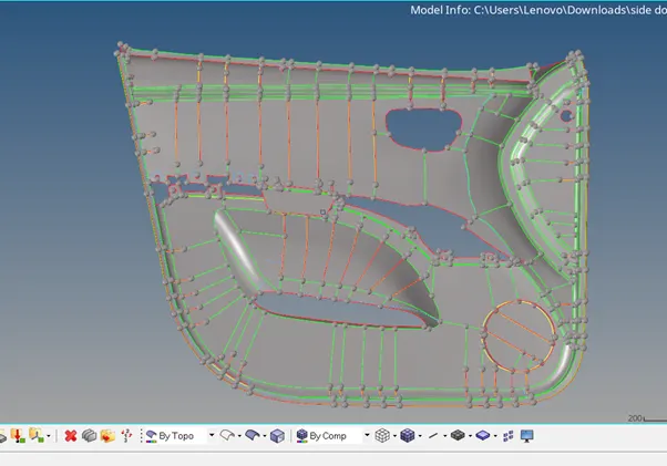
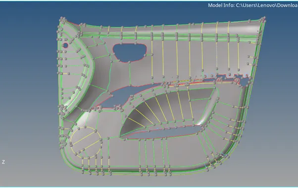
Meshing
After the midsurface is properly extracted and geometry cleanup is performed, the various surfaces are moved into different collectors according to their thickness. The collectors are appropriately named as per the thickness.
The surfaces are then meshed using the following criteria:
Meshing procedure:
For a complicated plastic model with varying thickness, we will be approaching every different thickness as a separate collector. This way we can quickly view, hide and mesh the surfaces. The different thicknesses are allotted with a tolerance of 0.1mm so as to achieve a satisfactory capturing of the parent body in the form of mesh. Any tapering ribs are meshed by dividing the rib into segments and the segments are separated into collectors according to the average thickness.
The settings used for meshing are as follows:
For our part, we will first mesh the ribs and smaller features, and then proceed onto the final base wall feature.
F10>SELECT SURFACE> TARGET LENGTH>ELEMENT TYPE>ELEMENT ORDER>MESH
- Mesh quality check and remeshing
After a mesh is generated, we have to check the mesh against the required criteria. This is known as Quality Check. This is performed in Hypermesh using following tools:
2D - Quality Index Tools - Check elems
Before we use these options, we have to enter the required mesh quality criteria in 2D - Element cleanup. This criteria is automatically imported into the Quality Index option which checks the mesh and displays the failing elements in distinct visual legends.
In Quality Check option we have to manually input the quality criteria and check the failing elements. Using a combination of both of these options we can get a good idea of the mesh quality.
Next step is to Remesh the model to address the quality issues highlighted in above step. For this we have various tools. We can remesh any uneven region of the mesh by selecting the elements and meshing them.
Following operations are carried out to improve the mesh quality:
- Remesh elements
- Drag tria - This tool is very handy to reposition the problematic trias so as to not stiffen the model at the important topological features.
- Combine elements
- Split elements
- Element cleanup - This tool automatically corrects the selected failing elements.
- Smooth - This tool smoothens out the shape/size of elements and tries to approach the ideal element shape as far as possible.
- Project nodes - This is used to project nodes onto topological features like edges or surfaces, so as to better capture the geometry.
- If there are warpage comes, break that quad to trias.
2d>edit element>split
- Some skew, maximum angle quad and minimum angle quad quality criteria can be corrected by element optimization.
2D>QUALITY INDEX>CLEAN UP TOOL>ELEMENT OPTIMIZE
N.B- USE ELEMENT OPTIMIZATION TOOL AS LESS AS POSIIBLE NEAR FILLET REGION. BECAUSE IT ALLOWS MESH TO DEVIATE FROM FEATURE LINE. USE THE PROJECT BY SELECTING TOOL(FROM MAIN MENU PAGE) TO ALIGN THE NODES ON FEATURE LINE
- Element failing for minimum and maximum quality criteria can be avoided by
- converting to tria
2d>replace>select node
- by increasing distance
geometry>distance>select two node>give distance>left click on graphical area
N.B--
- The mesh quality can make a huge difference in the outcome of a simulation, and hence, we have to optimise the mesh, one big factor is eliminating trias. Why do we need to eliminate tria elements? A simple 3 node tria element experiences constant strain on account of its shape function, which is very inaccurate. This results in a high articial stiffness at the element. This is why we have to eliminate or reduce tria elements as far as possible in any Stress result oriented simulations.
- We follow the following priority while remeshing and eliminating trias and rotational quads.
- Eliminate rotational quads
- Eliminate Tria elements adjacent to other tria elements
iii. Eliminate tria elements at topology edges
- Eliminate tria elements in the middle of the mesh Keeping above points in mind we eliminate tria elements as much as possible.
Thus we cleanup the elements to achieve a good mesh as much as possible. The final mesh looks as follows:
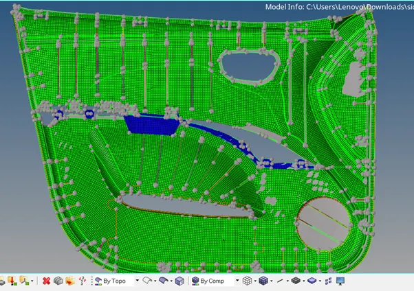
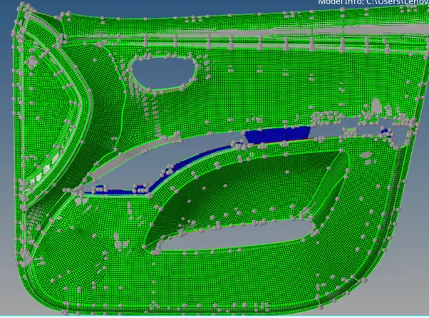
FREE EDGE CHECK
Now we go into wireframe mode and check for free edges and equivalence in the mesh by using Tool>edge>component> find edge. There should not be any free edges which are not topological free edges, as they denote discontinuity in the mesh.
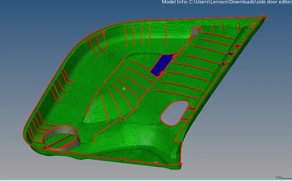
Equivalence is any discontinuous nodes in the mesh. Such nodes are very problematic as forces cannot be transmitted through that node. Any equivalence is cleaned up and the step is repeated by increasing the range tolerance till no more equivalence is registered.
Tool>edge>select all displayed elements >preview equivalence>equivalence
- Finally we turn on 3D representation of 2D elements and check how well the mesh is captured.
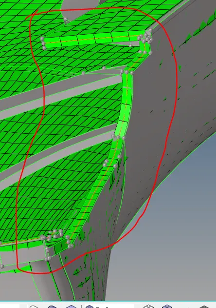
FINAL MODEL
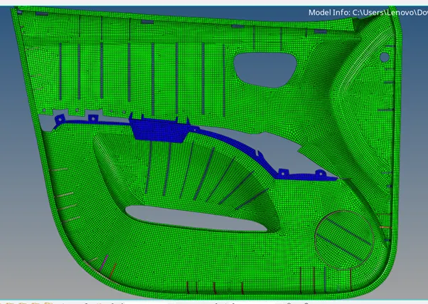
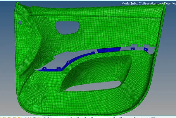
Conclusion-
- Though tria shell elements are not preferred in model that will use for crash analysis, we can not completely avoid tria. To make uniform grid we definitely need trias to keep near complex gemotry (converging-diverging).
- Rotating quad can be breakdown to two trias.
- Splitting the model to uniform geometrical shape like rectangle, pentagon, triangle gives the better mesh flow.
- Remeshing two opposite tria can give quad element. Same problem can resolved through drag tria command but that makes mesh waivy. Always use smooth command after using drag tria command
N.B- Combining two opposite tria that are parallel to each other in two splitted region are not advisable, as it deviates feature line.
- Project command can be use to align the grid points with construction line.
- Starat meshing from complex region like hole and conveging-diverging.