Parametric study on Gate valve.
Aim-: Parametric study on Gate valve.
Theory
Gate valve :
1. A gate valve, also known as a sluice valve, is a valve that opens by lifting a barrier (gate) out of the path of the fluid. Gate valves require very little space along the pipe axis and hardly restrict the flow of fluid when the gate is fully opened.
2. Gate valves are used to shut off the flow of liquids rather than for flow regulation.
3. Gate valves are mostly used with larger pipe diameters since they are less complex to construct than other types of valves
in large sizes.
Simulation Procedure :
Geometry :
1. Import the geometry.
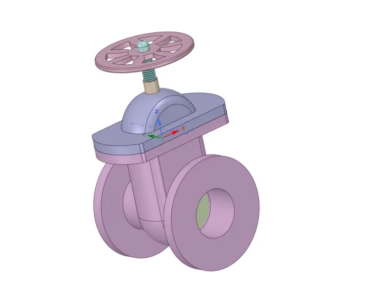
2.Hide the bottom part of valve and raise the disc at certain percentage and parametrize it.
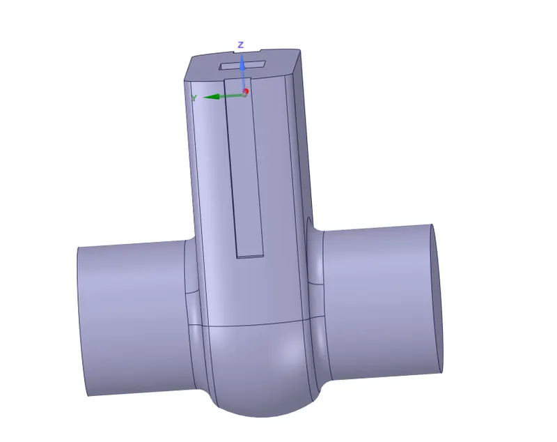
3.Now select the fluid volume and extend the geometry.
4.Update the volume body w.r.t current body, ensure it by using cutplane.
5.Finally suppress all parts except the fluid volume.
Mesh :
1. Name the faces like input, output.

2.Mesh the volume(we are going to use 7mm as element size).
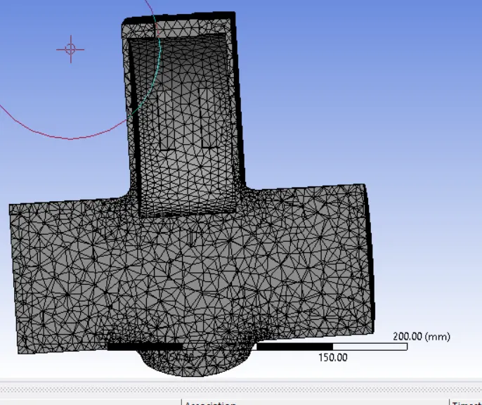
Element size Total Elements
7mm 109926
Setup :
1. Perform mesh check.
2. Set up gravity.
3. Set the viscous model.
4. Add material and set the same material in cell zones.
5. Now set the boundaries.
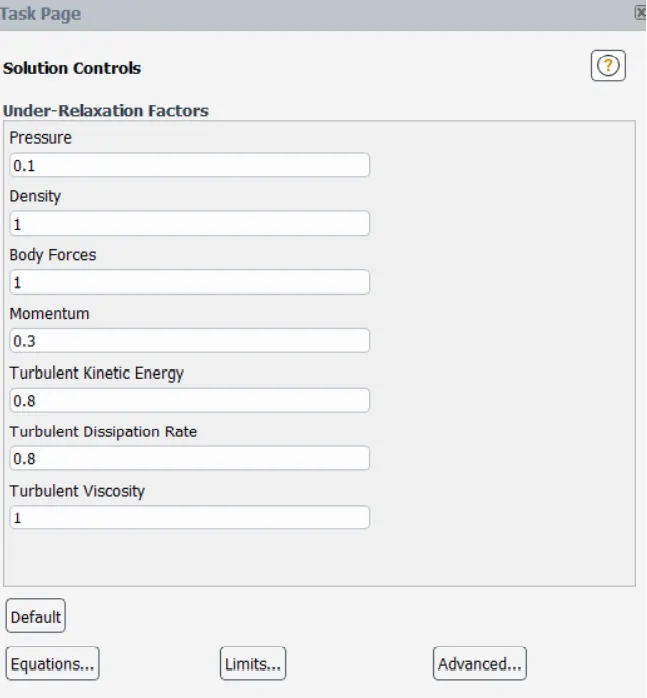
6. Set the solution method and under relaxation factors.
7. Create mass flow rate report definition.
8. Create the plane and set the velocity contour.
9. finally set some no. of iterations and rn the simulation.
Setup Inputs :-
1] Solver - Pressure Based Steady
2] Viscous Model - K-epsilon Realizable
4] Fluid - water
5] Boundaries - inlet - pressure inlet - 10 Pa
6] Solution method - SIMPLE(first order)
Under- Relaxing Factors :
Results :
1. Make the fluid volume visible and create a plane and color it with required variables.
4. This completes the simulation.
Parameters:
1. Set more no. of DP units and provide specific lift values.
2. Select the retain data option and update all the dp points so the solution runs automatically for all lifts and solves according to the current DP settings.
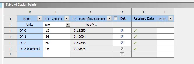
3. Now observe the mass flow rate for all lifts and calculate the Cv and Kv, Below are our simulation results of mass flow rate obtained at provided lifts
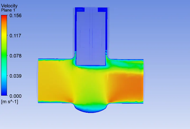
Case-1
Lift = 12
velocity
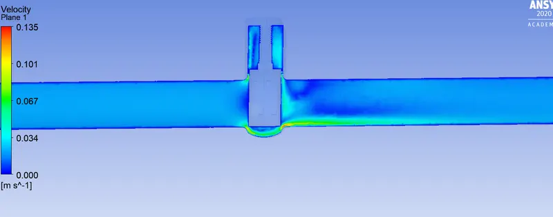
Case-2
Lift = 36
velocity
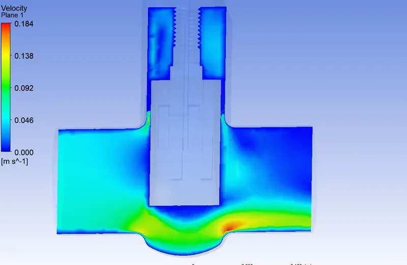
Case-4
Lift = 80
velocity
Flow coefficient :
The flow coefficient of a device is a relative measure of its efficiency at allowing fluid flow. It can be expessed as follows :
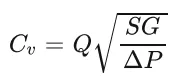
where,
Q is the rate of flow (expressed in US gallons per minute),
SG is the specific gravity of the fluid (for water = 1),
ΔP is the pressure drop across the valve (expressed in psi).
Flow Factor :
The metric equivalent flow factor is calculated using metric units.
`k_v` can be calculated from `c_v`using the equation :
`k_v` = .065`c_v`
Conclusion
1. As the lift value increases, so does the mass flow rate.
2. As the mass flow rate increases, there is increment in pressure drop.
3. Flow coefficient seems related to pressure, because when the pressure drop increases, so does the Cv.
4. And there is relation between Cv and Kv, where Kv = 0.865*Cv, so Kv also is related to pressure drop.