Roof challenge
DESIGN OF CAR’S ROOF
OBJECTIVE: The main objective of this project is to design the flanges and reinforcements required for the roof of a car and also justify the position of these reinforcements.
THEORY: We should keep in mind some points while designing a roof.
- Curved roof is always stronger than flat roof.
- The number and position of the reinforcements depend on the curvature and length of roof.
- We should always follow the master section while designing the roof.
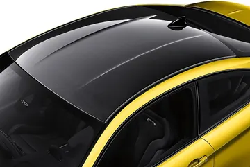
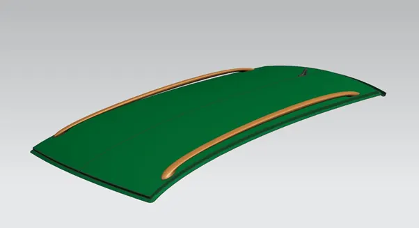
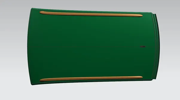
Roof of a car.
FRONT REINFORCEMENT/ FRONT ROOF RAIL (FRR): FRR is the front reinforcement. It joins the windshield and outer panel of the car.
Master Section of FRR:
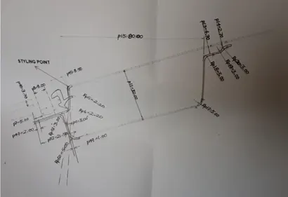
Follow the master section while designing the FRR
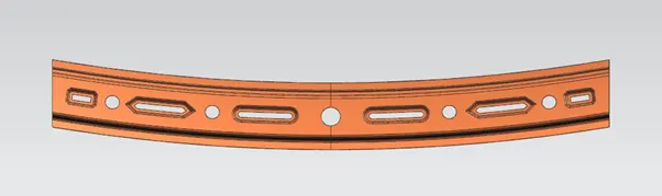
FRR after designing
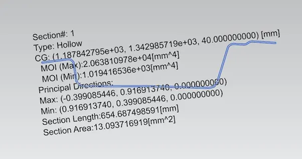
Section inertia of the FRR
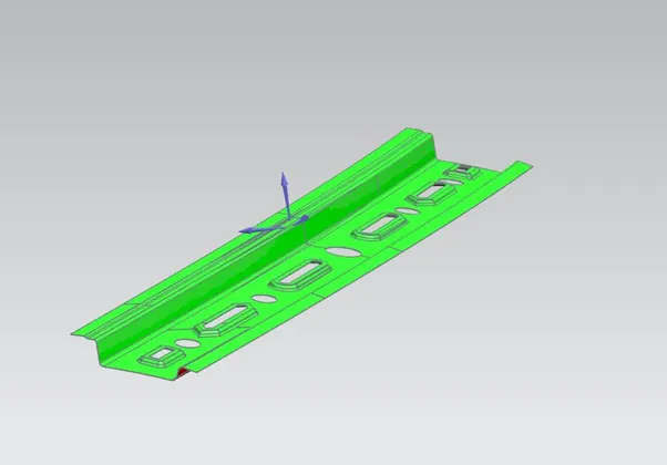
Draft analysis of the FRR
REAR REINFORCEMENT/ REAR ROOF RAIL (RRF): It is the rear reinforcement for the roof. It joins the backdoor to the outer roof panel. While designing we have to follow the master section.
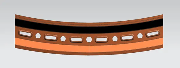
Rear Roof Rail after designing
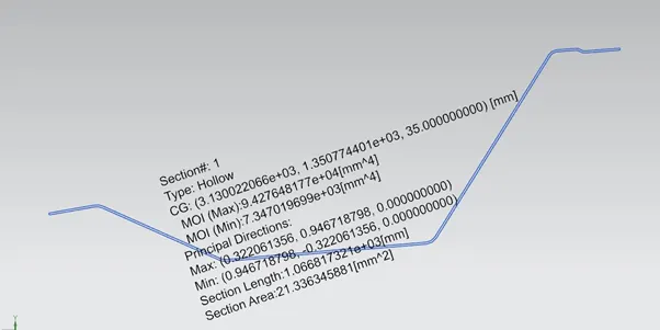
Section Inertia of RRF
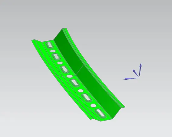
Draft analysis of RRF
BOW ROOF RAILS(BRR) AND ROOF REINFORCEMENT CENTRE(RRC)
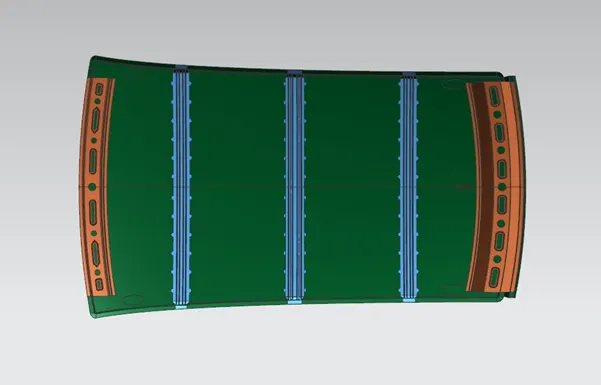
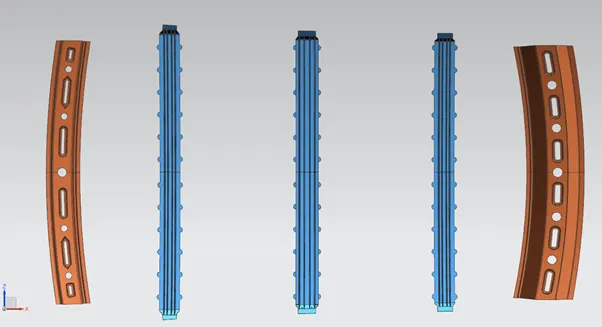
There are three bow roof rails for this roof and a roof reinforcement centre.
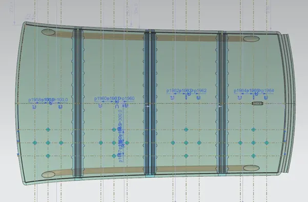
BOW ROOF RAILS : These are the bow roof rails positioned at front middle and end of the roof . bow roof rail 1 is placed after the front roof rail, while bow roof rail 3 is placed before the Rear roof rail. Bow roof rail is placed in the middle of the roof.
ROOF REINFORCEMENT CENTRE (RRC) : RRC and BRR2 is positioned at the same point. BRR2 is inside the RRC.
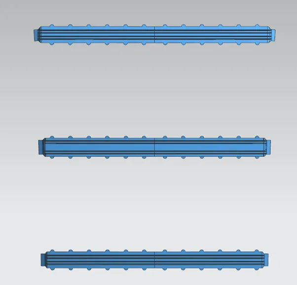
Three BRRs and the RRC
BRR1:
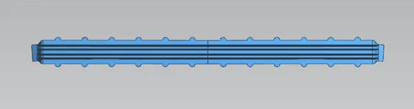
BRR1 after designing
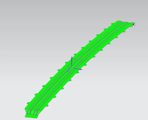
BRR1 Draft analysis
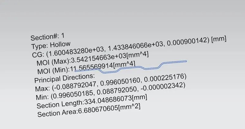
BRR1 Section Inertia
BRR2 and RRC:
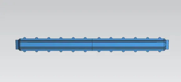
BRR 2 after designing
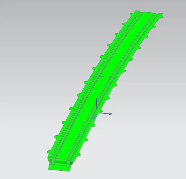
BRR2 Draft Analysis
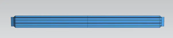
RRC after Designing
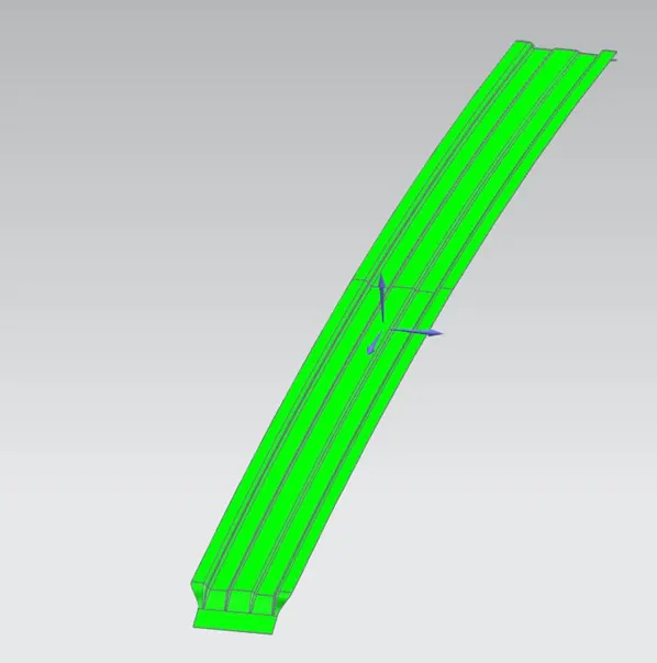
RRC Draft analysis
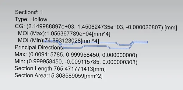
BRR2 and RRC Section Inertia
BRR3:
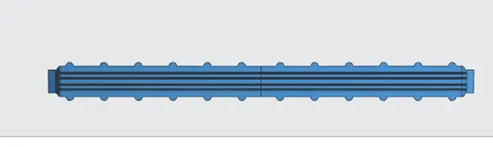
BRR3 after designing
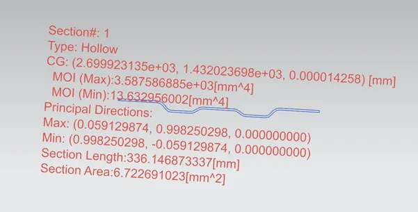
BRR3 Section Inertia
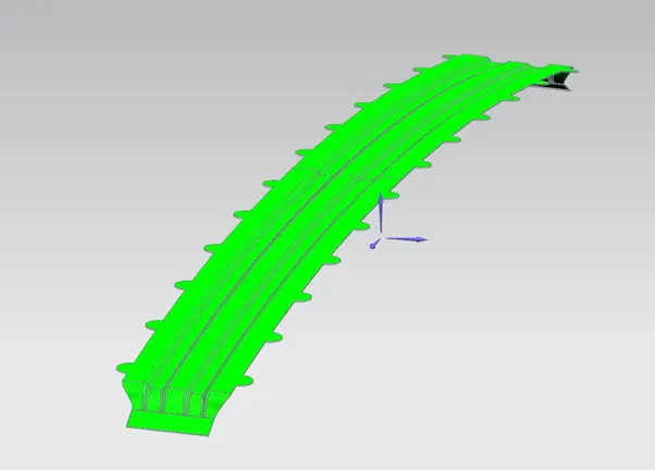
BRR3 Draft Analysis
CURVATURE STUDY OF THE ROOF AND CALCULATIONS TO DETERMINE WHETHER THE POSITIONING IS PROPER OR NOT
We can do the curvature study to see if the position we have given for the BRRs and RRC is proper or not. To determine this we have two conditions.
- Heat Distortion Criteria
- Snow load Condition
Heat Distortion Criteria:
W = [1.73 x 10^ (-3) x L] + [1.85 x 10^ (-8) x (R^2)/t] + [ 1.10x10^ (-3) x l] - 2.68
Judgement Condition: OK< 2.7> 3.1
Where,
L = Roof Length in X-Direction[mm] (Roof dimension in 0-Y)
R = Roof curvature
R = 2(Rx*Ry)/(Rx+Ry)
Rx = X curvature
Ry = Y curvature
t = Roof plate thickness [mm]
l = Bow Roof Span [mm]

Snow load Condition
Qr = [Iy x t2] / [α x s x [(Rx + Ry)/2]2 x 10-8]
Note: The Qr value given over here is correct. There was a typo error in the formula given in the video.
Where
α = My x Lx2 x 10-12, My = Y(Ly-Y)
Judgement condition = Qr ≥ 3.1
250 ≤ s ≤ 380
t = Roof plate thickness [mm]
Ly = Distance between the front and rear roof Rails on the Vehicle along with 0Y[mm]
Length of Roof panel with the centre point between Roof rail Front /Rear as the front and rear reference point.
Lx = Distance between the Left and Right end of the roof on the Roof BOW [mm]
Width of the roof panel exposed on the surface.
Y = Distance Front Roof Rail to Roof BOW [mm]
s = Distance for which Roof BOW bears divided load [mm]
s = L1/2 + L2/2
Iy = Geometrical moment of inertia of Roof BOW (Y cross-section) [mm4]
Rx = Lateral direction curvature radius of roof panel Y cross-section on Roof BOW [mm]
Roof panel curvature Radius of the Length Lx in Front view
Ry = Longitudinal Direction curvature radius of the Roof panel X cross-section on Roof BOW [mm]
Roof panel X curvature radius of length s in Side view
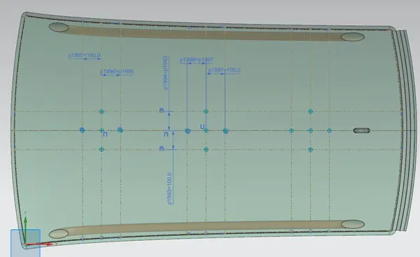

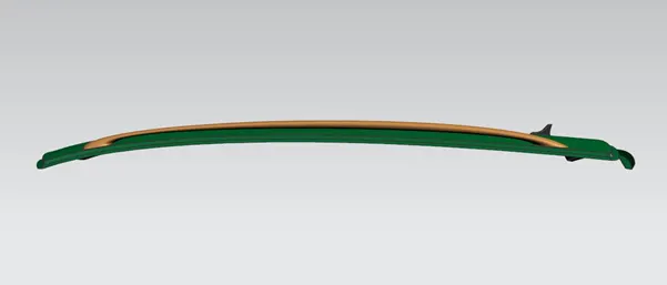
FINAL IMAGES
CONCLUSION: The position of the Bow Roof Rails is proper.