Hood design-Week 2
HOOD DESIGN USING NX CAD
AIM:
Our aim is to design a hood outer panel, inner panel and the necessary reinforcements. We have to make this into an assembly file along with striker and latch assembly aligned to the inner panel respectively.
Given Data
- A styling surface of the hood.
- Master section of the hood panel.
- Hemming data.
- Thickness of inner panel, outer panel, reinforcements.
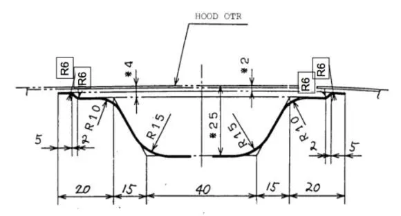
Master section of the hood panel
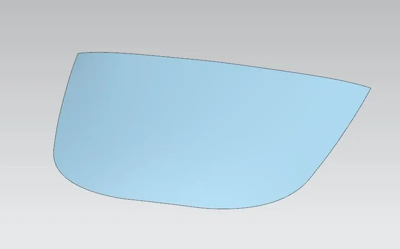
Styling surface
HOOD AND ITS COMPONENTS
A HOOD is also known as BONNET, It is a cover that rest over the engine. It is hinged to the engine compartment. The main purpose of hood is to provide access to the engine for maintenance and repair. A striker and latch is used to hold down the hood.
The main components or it is proper to say that the hood is an assembly of following parts
- Hood Outer Panel
- Hood Inner Panel
- Striker and Latch
- Hinge Assembly
Outer panel of the hood is visible to the customer, therfore it should have an aesthetic look. Hood Outer Panel functions as a metal cover for the hood inner panel. It is weak on its own. It is not capable of withstanding fore during impact.
Inner Panel of the hood is not visible to the customer but this is an engineering feature of the outer panel. Hood inner Panel provides strength for the outer panel of the hood.
Striker and Latch helps in holding down the hood to the body of the automotive.
Hinge Assembly consists of two parts i.e., the one that is attatched to the hood and the other which is attatched to the engine compartment.
Design Methodology
Design of Inner panel
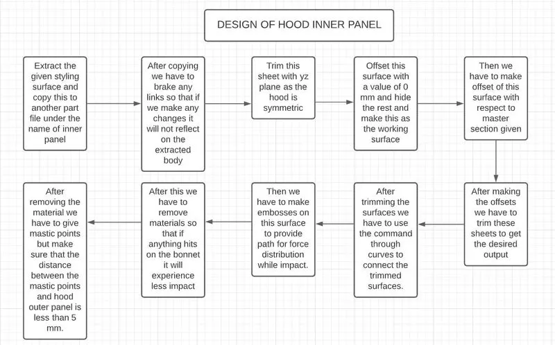
Design Procedure
- Extract the given styling surface and copy this to another part file under the name of inner panel
- After copying we have to brake any links so that if we make any changes it will not reflect on the extracted body
- Trim this sheet with yz plane as the hood is symmetric
- Offset this surface with a value of 0 mm and hide the rest and make this as the working surface
- Then we have to make offset of this surface with respect to master section given
- After making the offsets we have to trim these sheets to get the desired output
- After trimming the surfaces we have to use the command through curves to connect the trimmed surfaces.
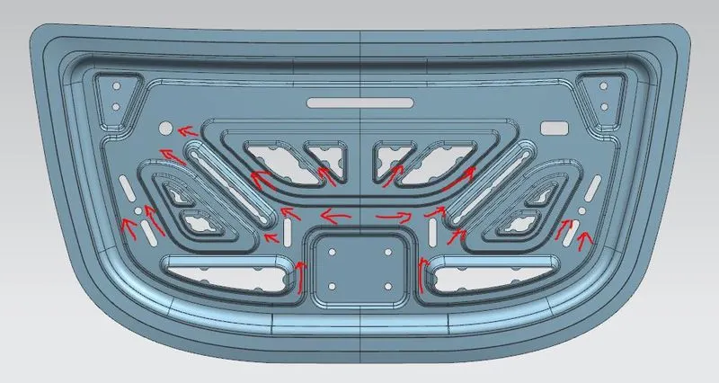
- Then we have to make embosses on this surface to provide path for force distribution while impact.
- After this we have to remove materials so that if anything hits on the bonnet it will experience less impact
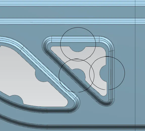
- After removing the material we have to give mastic points but make sure that the distance between the mastic points and hood outer panel is less than 5 mm.
- After making this we have to mirror this surface with yz plane and sew this together.
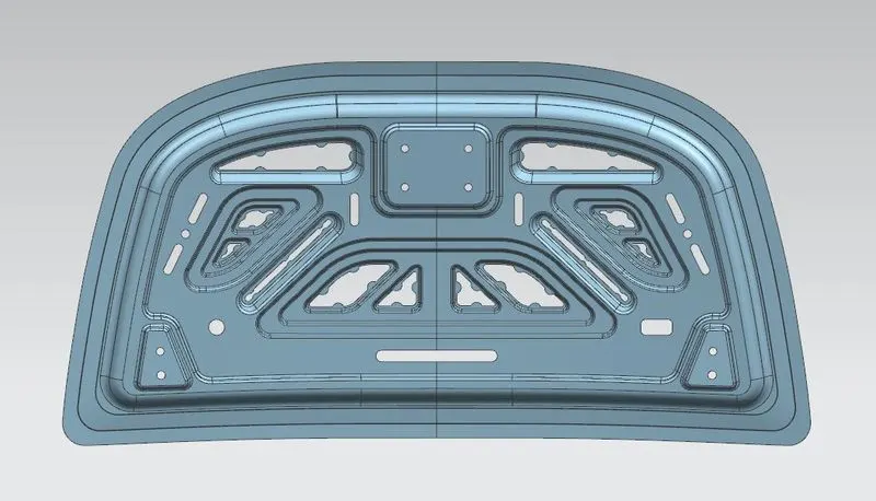
Embosses on the inner panel: They are designed to distribute the forces caused during an accident to outside rather than to the passenger compartment.
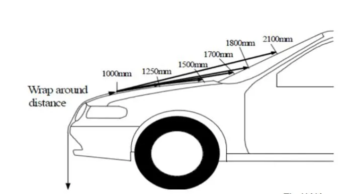
While designing the hood we have to consider the safety of passengers but at the same time we also have to consider the safety of the pedestrians if the car hits one. This improves the quality and standard of the car in international market. Whenever the car hits a person the impact on the pedestrian should be very minimum, for that we have to remove the materials from the hood inner panel. The positions for removal of materials can be find out using wrap around distance. The wrap around distance is the area that is covering the entire hood of the car. With the help of wrap around distance we can remove the materials for both adult and child impact zones.
Mastic points and Mastic sealant
Mastic points are points on the inner panels which is at a maximum distance of 5mm from the outerpanel. These points give a strength to 80mm diameter area. Mastic sealants are paste like materials which is applied between the outer and inner panel of the hood. It expands as heat is applied and it strengthens approximately to an area of 80mm diameter from the point at which it is applied.
Creating the Hinge emboss
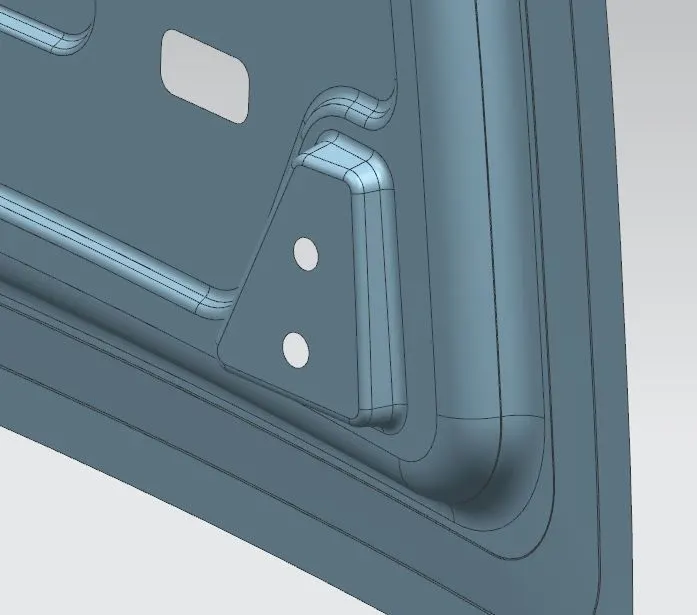
For fixing the Hinge on the hood inner panel we have to make an emboss on the panel. However we cannot offset the surface from the hood inner panel. This is because the hood inner panel is a curved surface. But the surface of the hinge is a flat one. So we have to make a flat emboss. This is done before mirroring the inner panel.
We can make this flat emboss through different ways but here we made the emboss using a datum plane .
- First we make a datum plane at a particular distance from the xz plane.
- Then we have to change the angle and make it as parallel as we can to the surface of the inner panel to which the hinge is to be fixed.
- After making the plane we have to draw a closed sketch so that hinge can be accomodated.
- We have to make emboss from this sketch to the inner panel.
- After that make edge blends on the corners.
Mounting the hinge assembly on the hinge emboss and mirroring the assembly
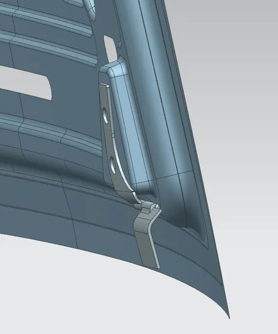
After making the hinge emboss we have to make the hinge assembly rest on the emboss. The hinge assembly should be in such a way that the hinge connecting to the engine compartment should be outside. Then we have to constraint the hinge assembly. First fix the inner panel of the hood, then select the assembly constraints in the assembly workbench. We have to constraint the hinge assembly in such a way that the axis of the assembly should be parallel to the x axis. The inner face of the assembly and flat surface of the emboss should be parallel and it should touch each other.
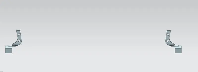
To mirror the hinge assembly we have to select the mirror assemblies in the assembly workbench and mirror the entire hinge assembly with respect to yz plane.
Making of Hinge Axis
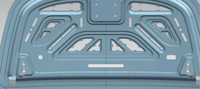
To make the hinge axis we have to make two points on the two hinge assemblies. Inorder to make the points we have to select the the arc between the two hinges on the assembly. After making the points we have to make a line with these two points.
Creating the functional circle to position the striker
Inorder to position the striker we need to know about how the hood moves up and down. For this purpose we have to make a circle with the centre as the hinge axis as the hinge help in closing and opening of the hood. So start a sketch on the yz plane and draw a circle with hinge axis as centre. After drawing this circle we have to make a horizontal line from the centre and then another line from the centre that is touching the circle. We have to make another line from this line which is tangent to the circle. Make the first two lines as reference and dimension the angle between them and the circle. We can later change this value to position the striker.
Giving constraints to position the striker with the functional circle
Before giving the constaints we have to make a datum coordinate system on the striker part file. And we have to specify the origin, x and y axis. The origin should be on the mid point of top straight edge. The x-axis should be parallel to the top edge of the striker. The y axis should be perpendicular to the front face of the striker. After fixing the coordinate system we have to make a sketch on the yz plane the sketch should a line perpendicular to face of the striker and it should be starting from the middle of the striker lock slot.
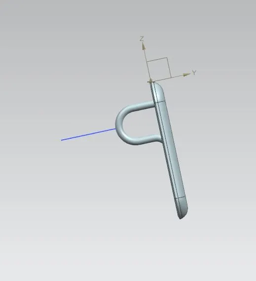
After making this sketch we have to constraint this sketch to the functional circle to position the striker. We have to give parallelconstraint between this line and the tangent line. the other constraint is that the end point of this line and the starting point of the tangent line must be touching each other.
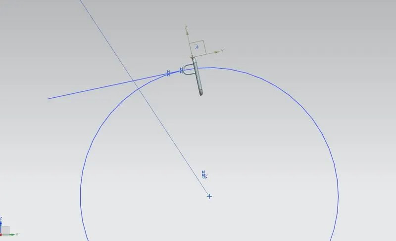
After constraining the striker we can now give dimension to position the stiker by going into the functional circle sketch.
Creating latch emboss
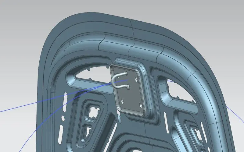
For creating the latch emboss we have to use a command called wave geometry in which we can make a copy of geometry from other part files. After making this copy we have to extrapolate the surface to all sides by a particular distance. Then with the help of law extension tool and trim and extension tool we can make the striker emboss.
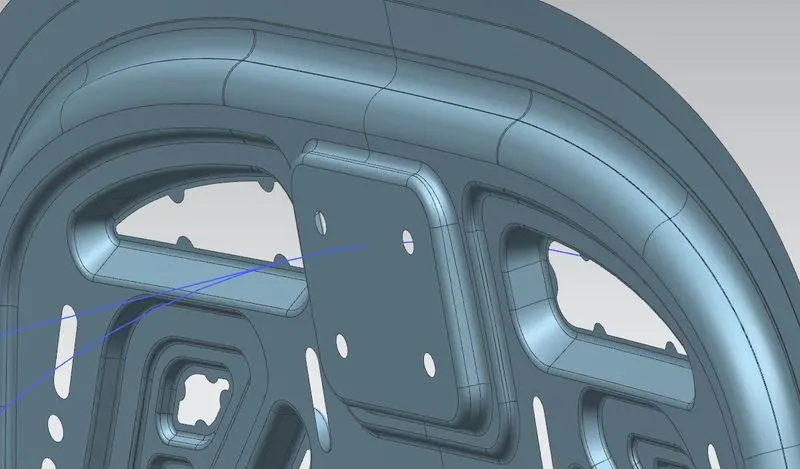
Then we fix the striker on the emboss.
Design of Hood Outer panel
Design procedure
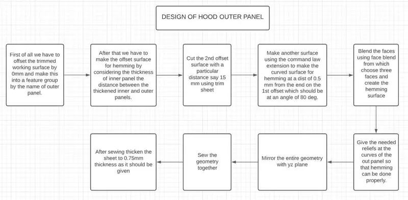
- First of all we have to offset the trimmed working surface by 0mm and make this into a feature group by the name of outer panel.
- After that we have to make the offset surface for hemming by considering the thickness of inner panel the distance between the thickened inner and outer panels.
- Cut the 2nd offset surface with a particular distance say 15 mm using trim sheet.
- Make another surface using the command law extension to make the curved surface for hemming at a dist of 0.5 mm from the end on the 1st offset which should be at an angle of 80 deg.
- Blend the faces using face blend from which choose three faces and create the hemming surface.
- Give the needed reliefs at the curves of the out panel so that hemming can be done properly.
- Mirror the entire geometry with yz plane.
- Sew the geometry together and thicken the sheet to 0.75mm thickness as it is be given.
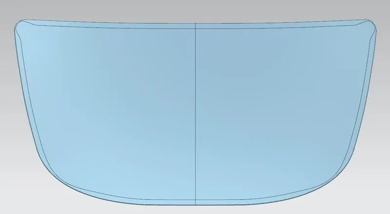
Hemming: Hemming is the process in which the inner and outer panel of the hood are joined. In this process the outer panel is wrapped around the inner panelto join both the panels. We also have to give reliefs so that the rollers doesnot face any problems while rolling through curved ends
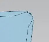

Reliefs given while hemming
After hemming the outer and inner panel looks like:
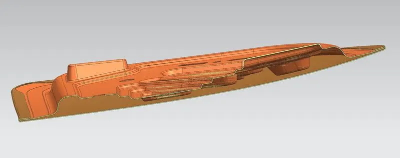
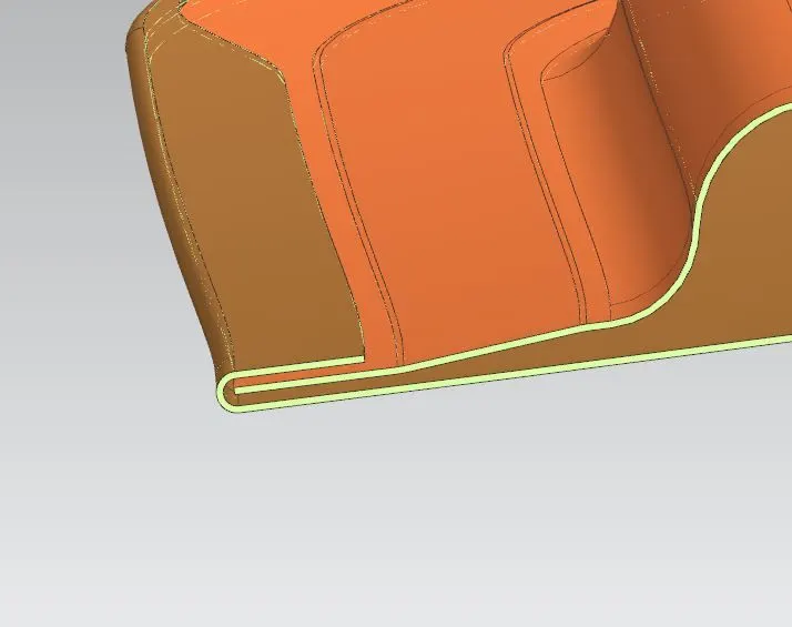
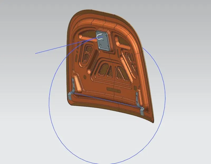
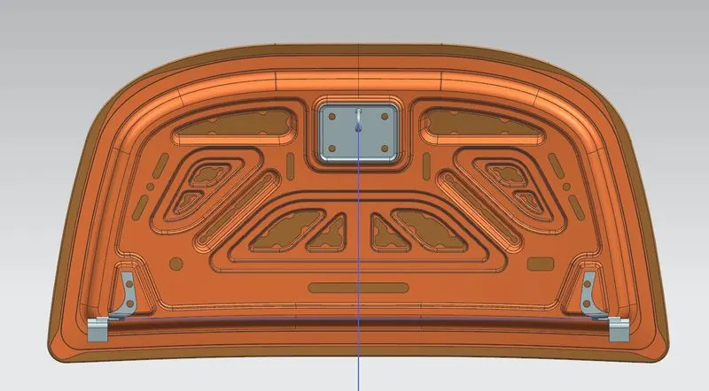
The final hood assembly looks like this
Conclusion
The software used for developing the hood is Nx 12.0. The inner panel and outer panel of the hood has been designed. Learned how to distribute impact force to outside rather than inside. The Striker position and hinge postion has been finalised. Hemming with necessary reliefs were studied.