Week 4 Challenge
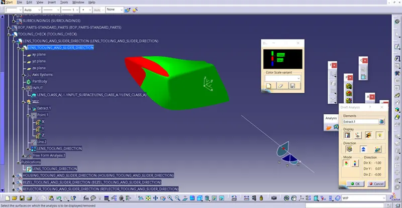
- Tooling Direction is the direction in which the die will be moving. The core will move apart from the cavity according to the tooling direction.
- The below image shows the draft analysis having 10 deg draft in tooling direction.
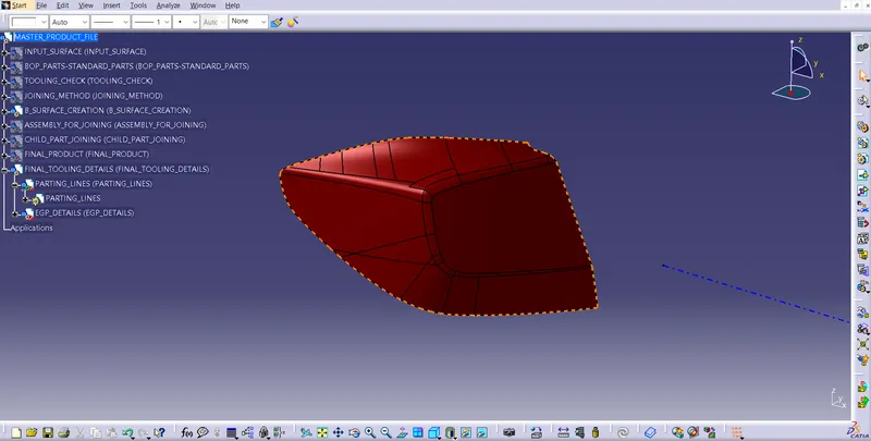
- The parting line is line which seperate the core and cavity. That is, when casting there will be a minute gap between the core and cavity and material sweeps into this gap and a small parting line will be formed which will not be visible but can be felt. you can also say that it is the border line in which the draft angle changes.
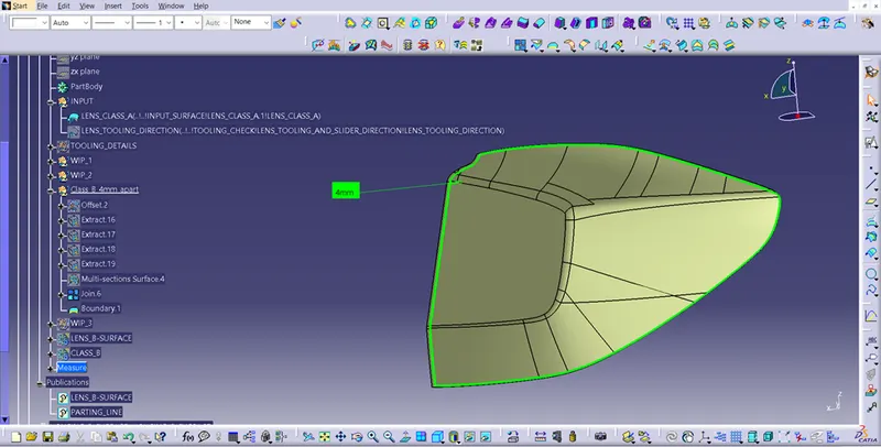
- A Class B Surface which is at an offset of 4mm distance is shown below.
- The parting line is the doted line in the orange color.
- The input, Class-A Surface, was given. The input given was separate isolated multiple surfaces. The detailed step of how the final model was created is explained below.
1. Join the surfaces together with 0.001 merging distance using the join option in Generative shape design workbench.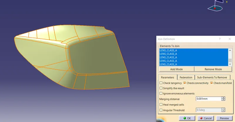
2. Once join operation is done create the Class B surface which is an offset(2.5mm) from the Class A surface towards inside.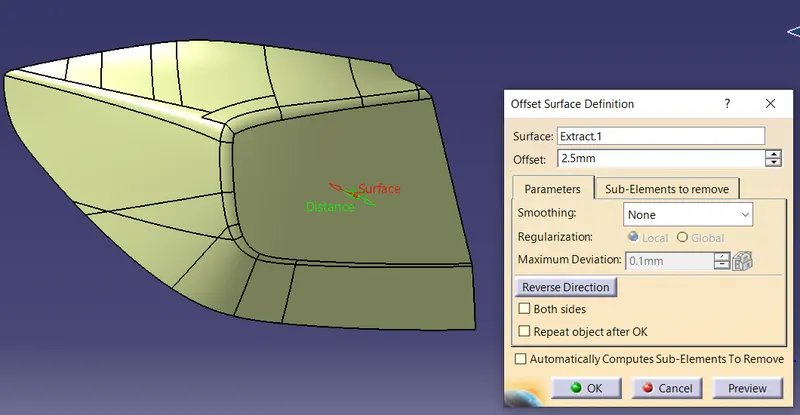
3. Create a tooling line which will be used as the tooling direction to check the draft analysis of the model.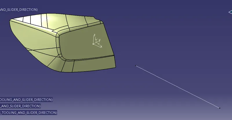
4. Once Class B surface is finished create class C surface which connects class A and Class B surfaces together, in order to do that extract the edges of both the sufaces and apply blend between them to to create once side of the Class C surface. Once that is done create a sweep for the remaining edge with tooling line created earlier as draft direction. Once that is done it will be like the image below.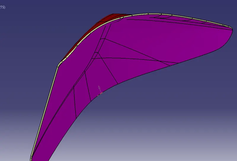
5. After that create a join between these three surfaces and convert it into solid using closed surface in part design workbench. Give the necessary fillets in the model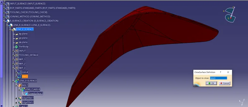
6. Once that is done create the welding channel. In order to create the channel we need to have a profile we will create that profile either by offsetting the edge of Class A or by creating sketch and control the profile by giving the distance from the projection and the angle between the horizontal and vertical directions. Once that is done sweep these lines in the tooling direction, trim and join these surfaces together. Then try to control the swept surfaces by adjusting the angle and distances in the sketches. For again modifying the curves on surface use spline and split commands to control the profile.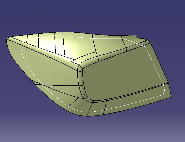
7. Once the profile is created sweep this profile in the tooling direction.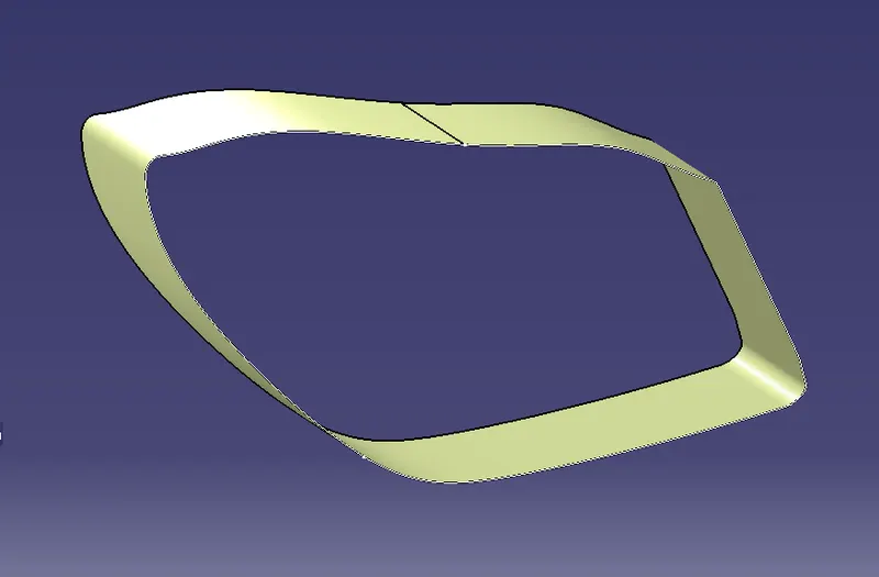
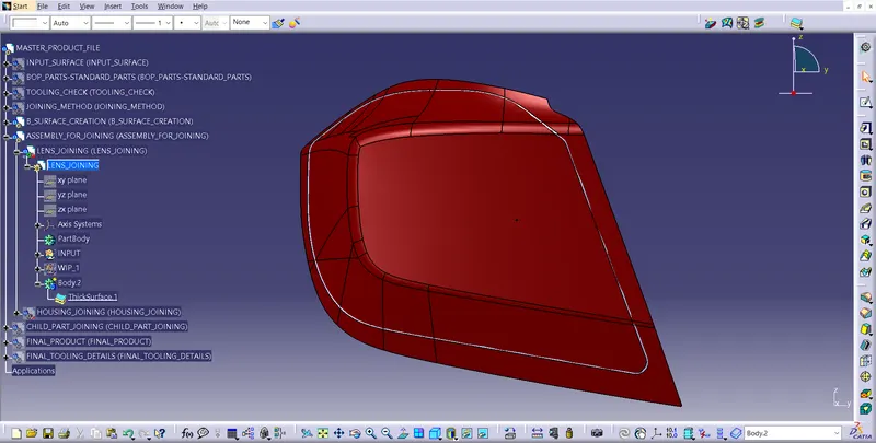
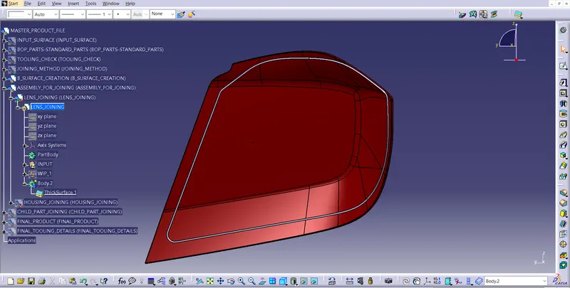
8. After that thicken the surface with 1mm to both sides.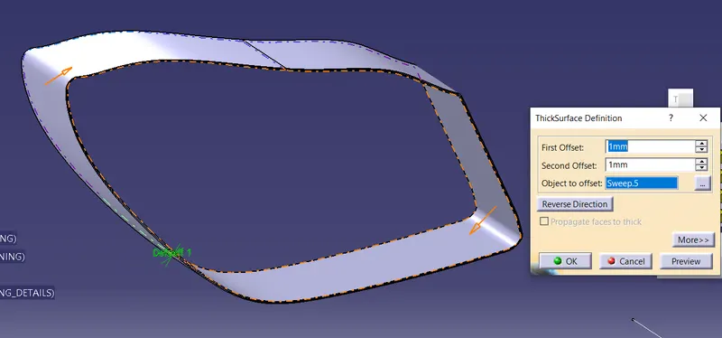
9. The final result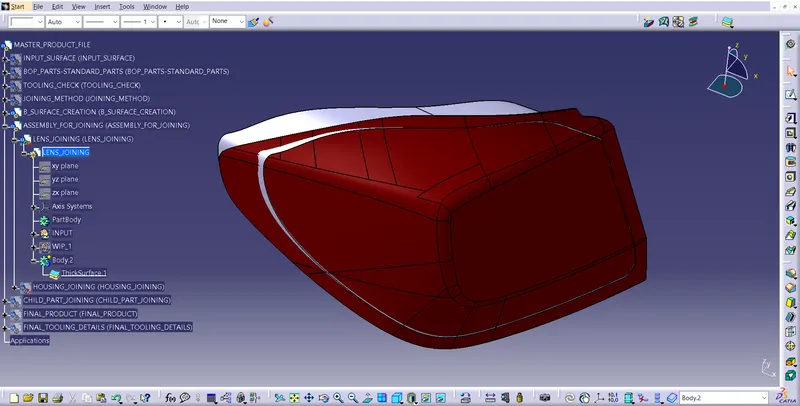
P.S: The attatchment contain the igs file of the model that i have created as this modelling is done in CATIA v5 R2021x.