Radar Mast & Final Assembly of Yacht
ASSEMBLY OF SUNSEEKER PREDATOR YACHT
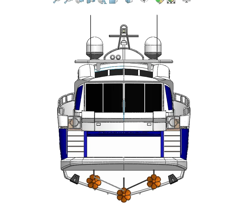
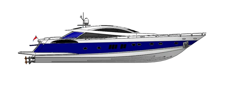
Final report of the Yacht
MODELLING AND RENDERING OF THE SUNSEEKER PREDATOR YACHT
Aim: Design of the sunseeker predator yacht using solid works software and rendering the photo realistic views using solid works visualization software
Objective: The main objective is to get more in touch with the surface and the solid features and commands to model the assembly of the yacht and render the photo realistic views using photoview360 and the solid works visualization software.
Introduction:
Creating a new part file Go to file -new part – Start a new sketch
Modelling procedure of the sunseeker predator yacht:
The main components are
- Propeller
- Radar
- Hull
- Garage Door
- Front Seat.
- Middle Seat
- Rear Seat
- Superstructure
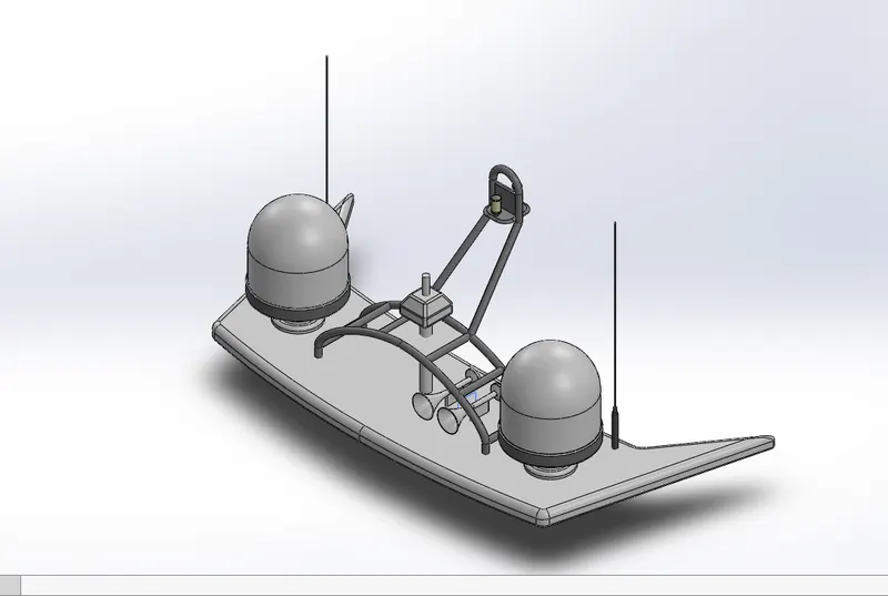
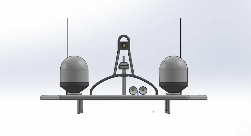
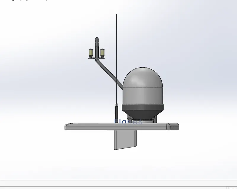
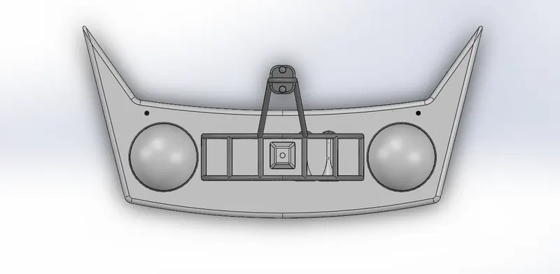
- Radar Mast
So, modelling of the individual part is done and final assembly is done by using all the above components
Challenge1:
2D sketch commands: Line, circle, Reference geometry(plane), spline, offset entities
Part1: Propeller
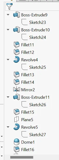
3D commands: Lofted Boss/Base, Mirror, Fillet, Revolve Boss/Base While designing the propeller component a revolve base is created and a lofted base is used to generate the circular patterned blades along the revolved part, apply fillet for the smooth edges and apply the appearances
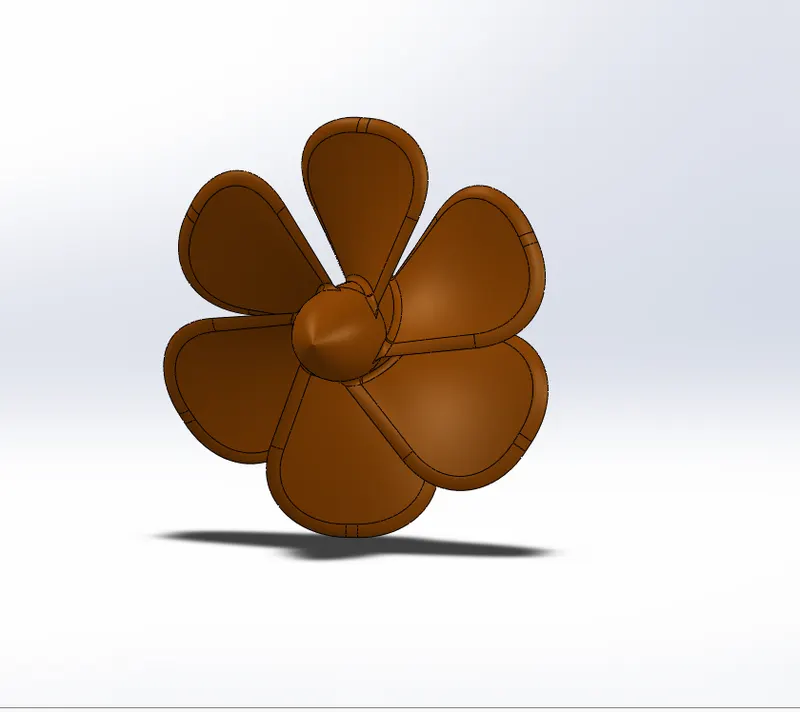
Note: All dimensions, fillets and appearances are specified as per the eBook lectures
Part2: Radar
3D commands: Extrude Boss/Base, extrude cut, fillet, text display
While designing the radar component the solid body is created using extruded boss and a hole is created at the centre by using extruded cut feature used for mating relation in the final assembly. Here the radar name is displayed as Sunseeker Yacht by using split line to commit the position of the text. Apply fillets and appearances as required
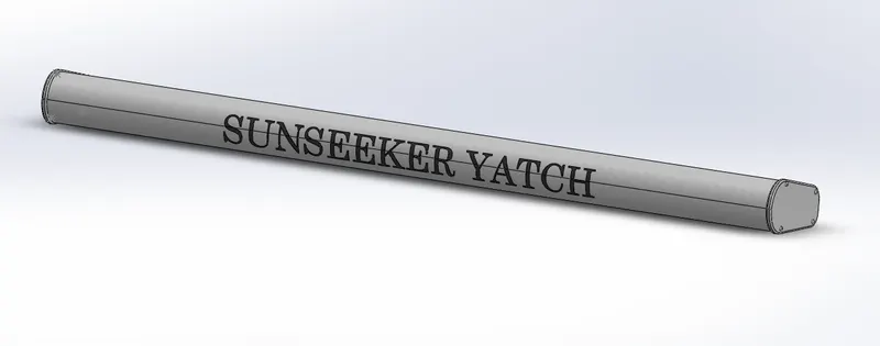
Note: All dimensions, fillets and appearances are specified as per the eBook lectures
Challenge2:
Part name: Hull of the sunseeker predator yacht
2D commands: Line, circle, spline, rectangle, ellipse, reference planes, offset entities
3d commands:
Solid features: Extruded boss/bass, swept boss/bass, extruded cut, revolve boss/bass, mirror, fillet, chamfer e.t.c
Surface features: extruded surface, lofted surface, knit surface, trim surface, extend surface, filled surface, swept surface.
First of all, create the blueprint sketches of the yacht with the corresponding planes like front, back, side ,top and bottom planes, so that we can able to mark the sketches at the desired location. Generally, we create one side of the part and mirrored the other end to create the whole structure. While designing the hull we use project curve feature by implementing two sketches in perspective planes to obtain a bonded sketch in the required plane with these sketches we complete the bottom end of the hull then use the knit option to combine the structures all together and form a merge as a solid body. Then the railing part is designed by using project curve feature and swept boss bass command. A part of the backend is cut extruded to maintain room for the other components and closed it with garage door while assembling. Apply the adaptable appearances and apply decals for the steps portion and the hull base to vibrant the ambience. Save the model.
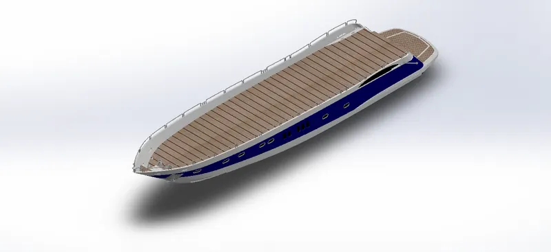
Note: All dimensions, fillets and appearances are specified as per the eBook lectures
Part name: Garage door of the hull
3D commands: Extruded boss/base, Extruded cut, fillet, chamfer.
While designing the garage door the cut extruded part of the hull design is imported and apply desired features to turn off the part as a requested component which is used as a closing for the hull backend
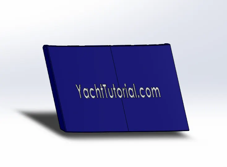
Note: All dimensions, fillets and appearances are specified as per the eBook lectures
Challenge3:
2D commands common for all 3 seats: Line, circle, fillet, spline , arc, reference plane, convert entities and offset entities
Part name: Front seat
3D surface features: Surface extrude, swept surface, dome, fillet, chamfer, surface loft, surface fill, surface trim, knit surface, Revolve, mirror
First of all, import the surface bodies from the hull component to ensure the base for the front seat this can be done by
Insert- Part- browse components - Hull- Mark the surface bodies -click ok
Then try to hide the unnecessary blueprint sketches and start sketching the model front seat with adopted features from surface and solid sections . Then mirror the individual components to form the front seat of the sunseeker predator yacht
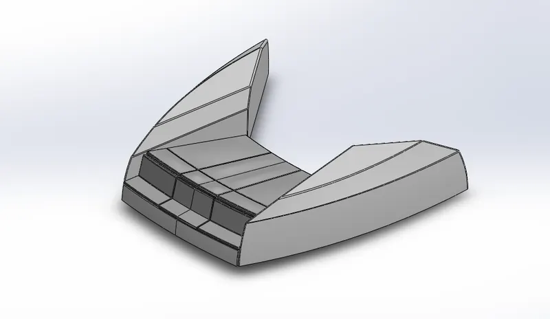
Note: All dimensions, fillets and appearances are specified as per the eBook lectures
Part name: Middle seat
3D features: Boss extrude, cut extrude, fillet, chamfer, dome, mirror
Insert- Part- browse components - Hull- Mark the surface bodies -click ok
While modelling the middle seat the above mentioned features are utilized and model is generated
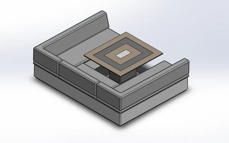
Note: All dimensions, fillets and appearances are specified as per the eBook lectures
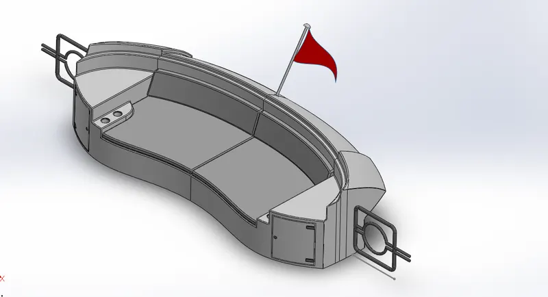
Part name: Rear seat
3D features: Surface sweep, surface offset, surface loft, sweep, fillet, chamfer, boss extrude, cut extrude, combine , surface trim, surface extend, surface knit, mirror
Insert- Part- browse components - Hull- Mark the surface bodies -click ok
First of all hide the unnecessary blueprints and start sketching on the surface body with the help of the blueprint markings.Generate the different solid bodies and mirror them to form the entire component.apply fillets and appearances to different solid bodies
Note: All dimensions, fillets and appearances are specified as per the eBook lectures
Challenge4:
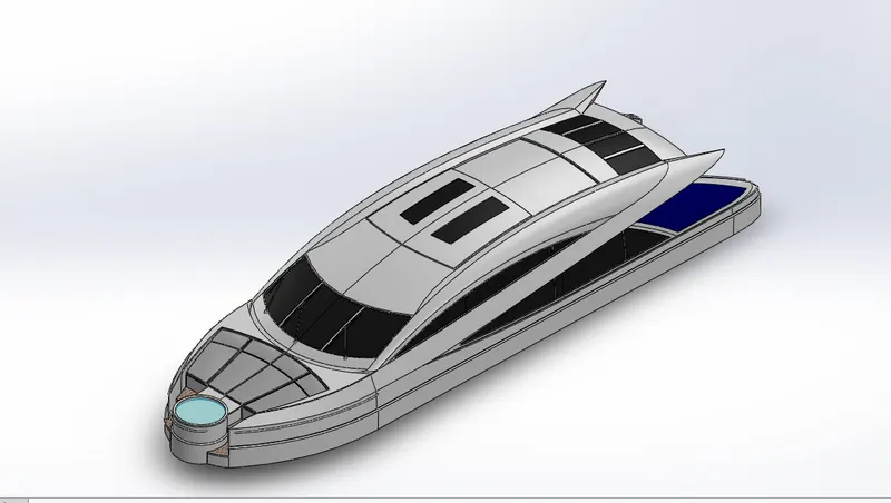
Part name: Superstructure
2D commands: Line,circle , spline, arc, rectangle, reference plane, convert entities, offset entities,
3d commands:
Solid features: Extruded boss/bass, swept boss/bass, extruded cut, revolve boss/bass, mirror, fillet, chamfer etc.
Surface features: extruded surface, lofted surface, knit surface, trim surface, extend surface, filled surface, swept surface, ruled surface, delete face, offset surface,
First of all import the blueprints and the surface bodies from the hull
Insert- Part- browse components - Hull- Mark the surface bodies -click ok
Now start sketching on the surface bodies using features like extrude surface, extend surface and so on.
- The extend surface helps us to extend the surface up to some extend by providing distance
- The surface fill helps us to intrude the surface between a closed loop by selecting the looped sketches
- The surface loft helps to fill up the boundary by selecting the two profile curves and two guide curves
- The knit surface used to knit that implies combine the different surfaces as single surface
- The trim surface used to remove the unnecessary surface to be removed
- The offset surface is used to copy the certain surface up to some distance
So, with the help of these features create the desired model structure
Use the cut extrude feature to mark the sketch on the appropriate planes to show the resemblance for the mirrors and the windows, apply the dark appearances for the mirrors and windows sections
Use swept boss to model the handles for the structure.
Use boss extrude, cut extrude and the 3d sketches to create wipers for the windows
Select the top most surface as the reference for the Radar mast
Apply fillets to avoid sharp edges and apply appearances
Note: All dimensions, fillets and appearances are specified as per the eBooklectures
Part name: Radar mast
3D commands: Boss extrude, fillet, mirror, shell, dome
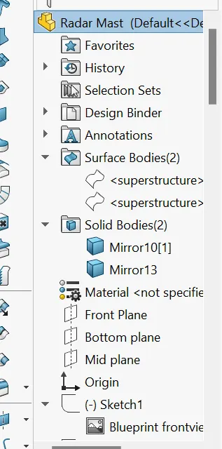
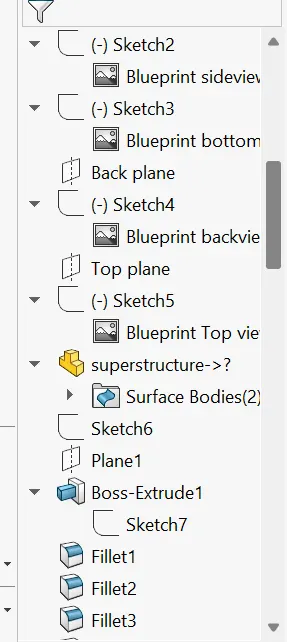
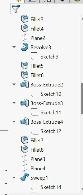
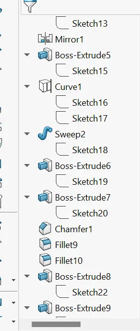
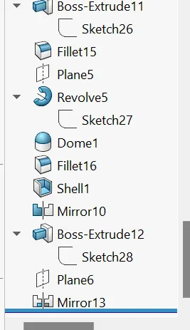
While modelling the Radar mast the copy reference surface which we created while designing the superstructure is taken as a bottom reference and hide the unnecessary blueprints, start sketching according to the eBook and mirror the components to form a single assembly.
Note: All dimensions, fillets and appearances are specified as per the eBook lectures
Final challenge: Assembly of a sunseeker predator yacht
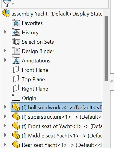
Steps involved: open a new assembly file -Browse all the part models in the window -start doing assembly
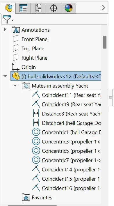
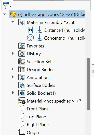
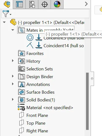
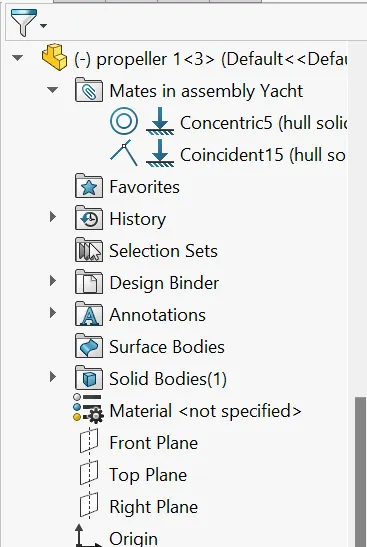
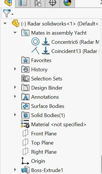
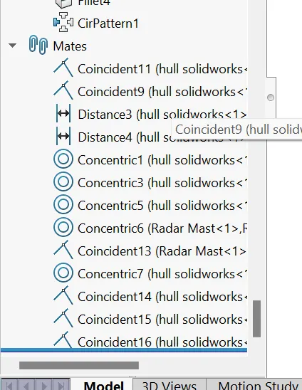
The assembling of a Sunseeker predator Yacht is done by applying some mating constraints with respect to Hull
The following mates are:
- Coincident mate
- Tangent mate
- Distance mate
- Concentric mate
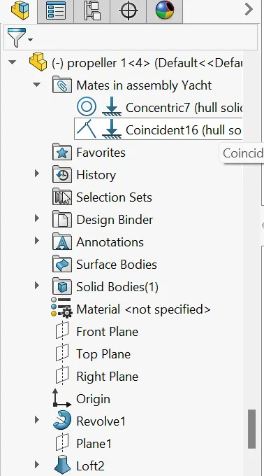
Here the components are fixed automatically with respect to the hull because during design the surface bodies are incorporated from the hull so, they fix automatically. And remaining components are inserted by using suitable mates
Keep an eye on the constraints as sometimes they can be over defined and make the assembly to mark an error
In this particular assembly some of the components are in the float situation as they are the moving ones like(Propeller, Radar, Garage door) so, better to form the assembly with underdefined mates rather than of fixing them in turns encounter an undefine body assembly.
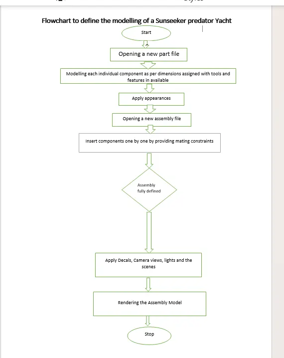
Flowchart to define the modelling of a Sunseeker predator Yacht
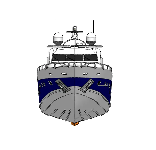
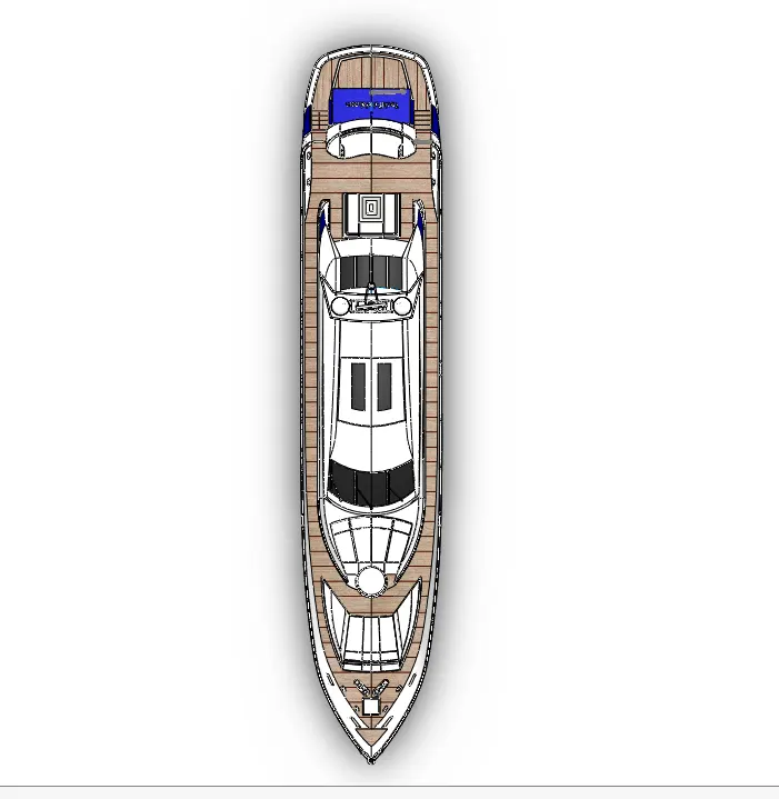
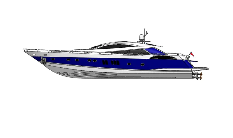
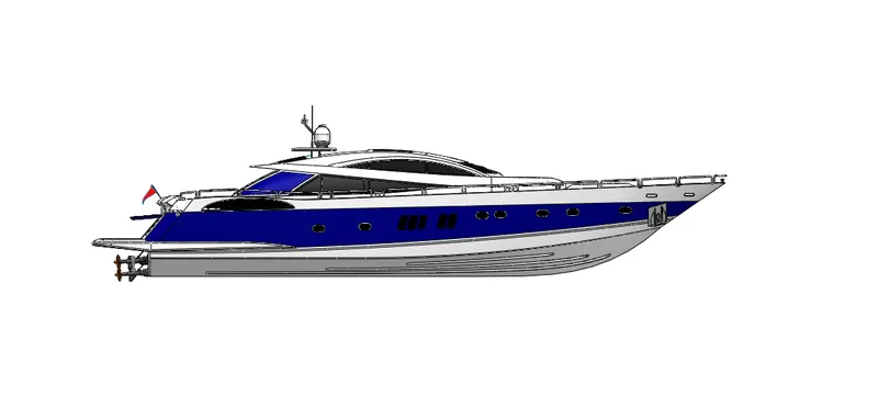
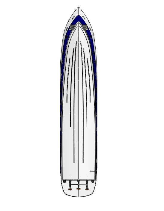
Assembly views of Sunseeker predator Yacht
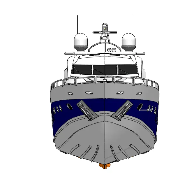
Front View:
Top view:
Right side view:
Left side view:
Bottom view:
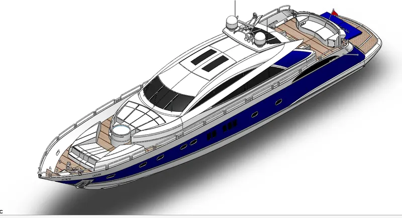
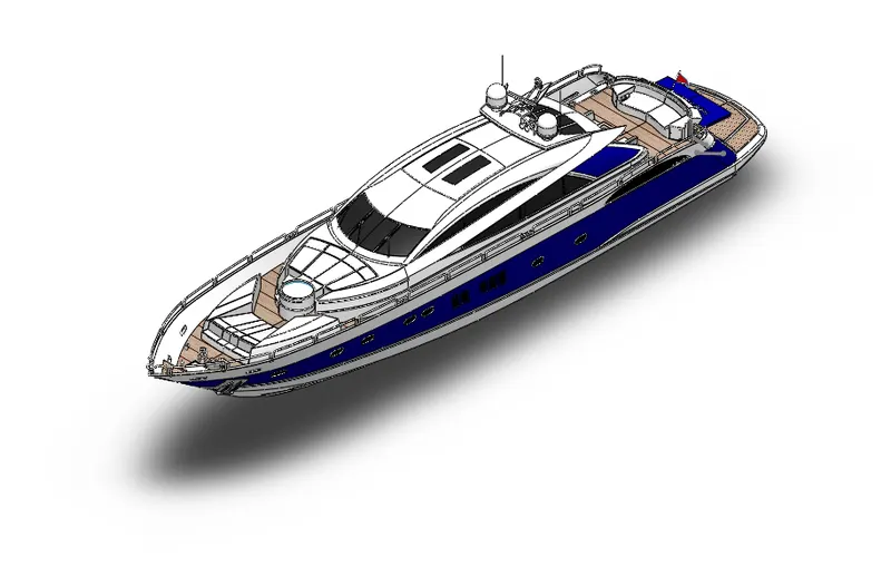
Isometric view:
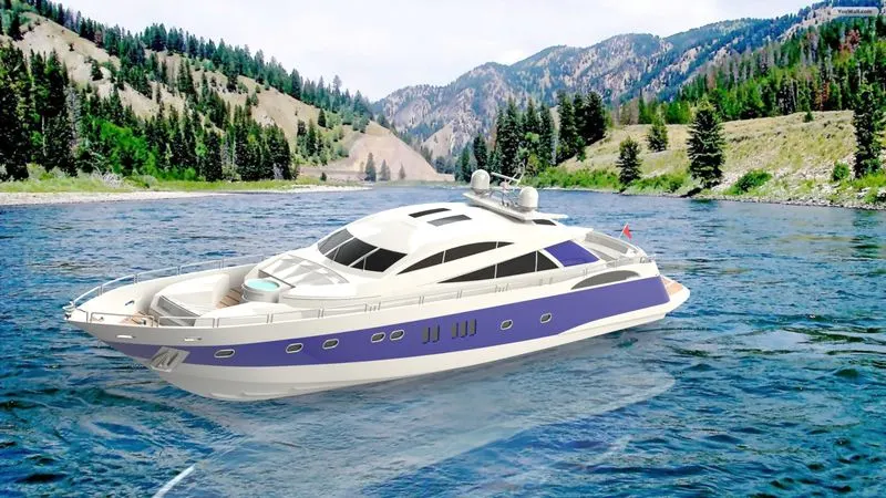
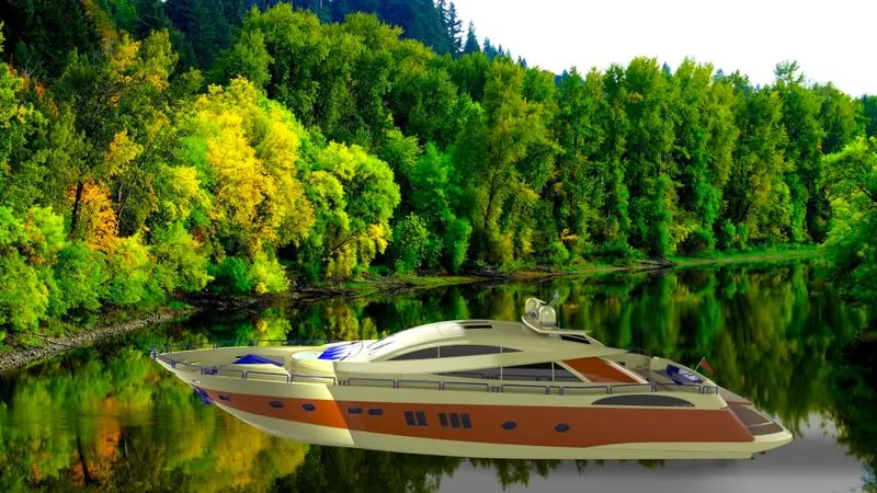
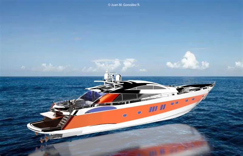
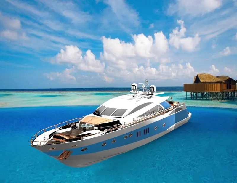
Solid works visualize:
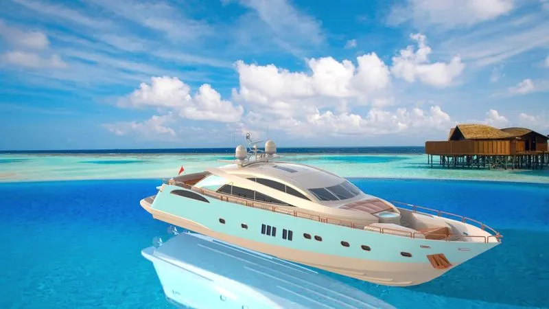
Solid works visualize is a software intends to render the Sunseeker Predator Yacht by using various commands and the features to obtain a more realistic render view
The commands generally include:
- Adding scenes and backgrounds
- Adding new appearances
- Adding decals
- Creating shadows
The Solid words visualize render view be like
Conclusion:
Thus Modelling, assembling and Rendering of an Sunseeker Predator Yacht is completed by using Solid works software.
Solidworks visualize render images: