Project 2 Adaptive Cruise Control
Aim :- Develop a MATLAB Simulink Model for Adaptive Cruise Control feature used in Automotive Vehicle
Objective:-
- To develop a Adaptive Cruise Control feature as per the Requirement Document using MATLAB Simulink.
- While Developing the Adaptive Cruise Control Simulink Model, we have follow all the MBD related processes such as Requirement Tagging & Traceability file.
- Creating a SLDD (Simulink Data Dictionary)file for storing the input/output signals and constant parameters.
- The above model has to be checked for MAB Guidelines in the Model Advisor .
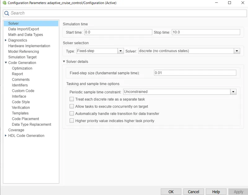
- Configuration Parameter (Solver settings) for the particular model has to be change and choose sample time for all signals as 0.01s. In Configuration Parameters, select enable “Support Floating Numbers” under Code Generation settings.
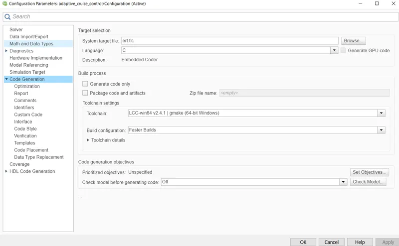
- Use of Embedded Coder to generate the code. While choosing code generation, Storage class for Input signals: ImportedExtern; Storage class for Output signal: Export to File; Storage class for local signals: localizable; Storage class for calibration signals: Const.
Theory :-
ADAPTIVE CRUISE CONTROL (ACC) :-
- Adaptive cruise control (ACC) is a system designed to help road vehicles maintain a safe following distance and stay within the speed limit.
-
Control is based on sensor information from on-board sensors. Such systems may use a radar or laser sensor or a camera setup allowing the vehicle to brake when it detects the car is approaching another vehicle ahead, then accelerate when traffic allows it to.
fig.1 Radar Detection in Adaptive Cruise Control
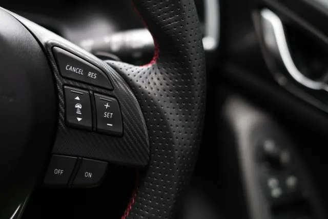
fig. 2 Cruise Control Button of Steering Wheel
-
ACC technology is widely regarded as a key component of future generations of intelligent cars. They impact driver safety and convenience as well as increasing road capacity by maintaining optimal separation between vehicles and reducing driver errors. Vehicles with autonomous cruise control are considered a Level 1 autonomous car, as defined by SAE International.
-
When combined with another driver assist feature such as lane centering, the vehicle is considered a Level 2 autonomous car.
-
Adaptive cruise control does not provide full autonomy: the system only provides some help to the driver, but does not drive the car by itself.
-
ACC functions by sensory technology installed within vehicles such as cameras, lasers, and radar equipment, which creates an idea of how close one car is to another, or other objects on the roadway. For this reason, ACC is the basis for future car intelligence.
-
These sensory technologies allow the car to detect and warn the driver about potential forward collisions. When this happens, red lights begin to flash, and the phrase 'brake now!' appears on the dashboard to help the driver slow down. There might also be an audible warning.
Types of Adaptive Cruise Control :-
(1) Radar-Based Systems :-
According to eInfoChips, radar-based systems work by placing radar-based sensors on or around plastic fascias to detect your vehicle's surroundings. Each radar sensor works together to create a comprehensive picture of the vehicle's proximity to other cars or potentially hazardous objects. This type of sensor can look different depending on the design and model of the car.
(2) Laser-Based Systems :-
As mentioned by Electronic Design, this type of ACC system operates out of a large black box typically placed in the grille of your vehicle. It uses laser technology to detect the proximity of objects to your car. It does not operate well during rainstorms and other weather conditions.
(3) Binocular Computer Vision Systems (Optical) :-
According to ExtremeTech, this is a relatively new ACC system put into use in 2013. It uses small cameras that are placed on the back of a vehicle's rearview mirror to detect front-facing objects.
(4) Assisting Systems :-
Assisting systems are radar-based add-ons that customers can buy together. These pre-crash systems can offer lane control, brake assistance, cruise control, proximity alerts to objects like corners, and steering power.
(5) Multi-Sensor Systems :-
According to Fierce Electronics, adaptive cruise control systems sometimes integrate more than one type of sensor to aid in a vehicle's operation. Multi-sensor systems incorporate several different sensor types to provide a driver with advanced information. These sensors might include GPS data equipment or cameras to gather information about a vehicle's geographic environment and proximity to other cars.
(6) Predictive Systems :-
As mentioned by Autoblog, prediction systems are a type of ACC that uses sensory data to predict the actions of neighboring vehicles. This means that your car might slow down to brace for another vehicle suddenly switching lanes and, in doing so, promotes passenger safety.
Adaptive cruise control is evolving each year. Car companies are continuously making adjustments to this technology and, in doing so, creating more common and affordable options that can be purchased with a new car or added to older car models, making driving safer for everyday people.
Advantages of Adaptive Cruise Control :-
- Cars with this technology will keep the adequate spacing between them and other vehicles. These space-mindful features will also help prevent accidents that result from an obstructed view or close following distance.
- Similarly, ACC will help maximize traffic flow because of its spatial awareness. As a driver, you don't have to worry about your speed, and instead, you can focus on what is going on around you.
Limitations of Adaptive Cruise Control :-
- One of the main faults in this system is the fact that it is not entirely autonomous.
- The driver of the vehicle still needs to practice safe driving habits that will work in tandem with this technology to produce the best results.
- Similarly, adverse weather conditions like snow, rain, or fog might confuse the system's sensors, as well as environmental factors such as driving through tunnels.
Development of Adaptive Cruise Control Model :-
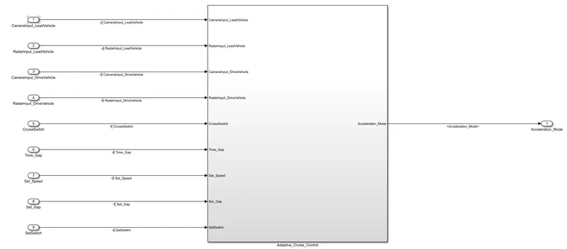
fig.3 Main subsystem of Adaptive_Cruise_Control
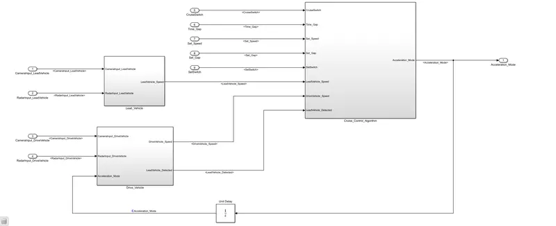
fig.4 Inside the main subsystem of Adaptive Cruise Control
- In the Adaptive Cruise Control model, we have given the total 9 nos. of input signals i.e. CameraInput_LeadVehicle, RadarInput_LeadVehicle, CameraInput_DriveVehicle, RadarInput_DriveVehicle, Time_Gap, Set_Speed, Set_Gap, CruiseSwitch, SetSwitch and with the logic, we are getting one output signal i.e. Acceleration Mode.
- This control logic will take into consideration all these above input signals and if there is no lead vehicle detected by Camera and Radar sensor of Drive Vehicle, then Adaptive Cruise Control (ACC) will will provide the required acceleration to the vehicle to meet the speed requirement set by driver.
- if there is a lead vehicle detected by Camera and Radar sensor of Drive Vehicle in their range, then Adaptive Cruise control (ACC) will will automatically reduce the acceleration of the vehicle even if speed set by driver by engaging collectively into accleration and braking control of the system. This is used even if there is heavy traffic jam.
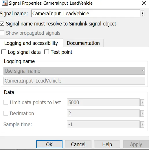
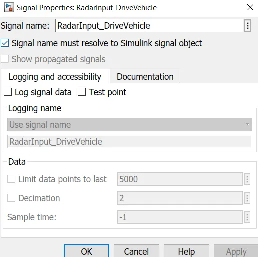
- This total 9 inputs signals are generated / used for first time hence, we will resolve the same by right clicking on the particular signal properties.
- Screenshot of resolving of some input signals are as under;
Requirement1 - Lead Vehicle :-
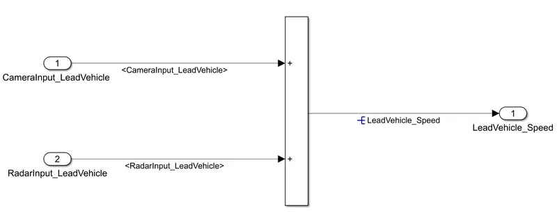
fig. 5 Lead Vehicle Subsystem
- Lead Vehicle is a vehicle which is driving in the road ahead of our drive vehicle. In the Lead Vehicle subsystem, two input signals i.e. Signal Name: CameraInput_LeadVehicle & RadarInput_LeadVehicle are added and the corresponding output is read as Speed profile output (Signal Name: LeadVehicle_Speed).
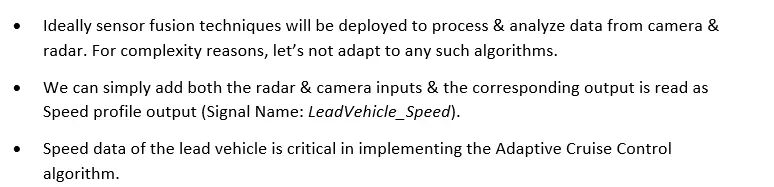
- Ideally sensor fusion techniques will be deployed to process & analyze data from camera & radar. For complexity reasons, let’s not adapt to any such algorithms.
- Speed data of the lead vehicle is critical in implementing the Adaptive Cruise Control algorithm.
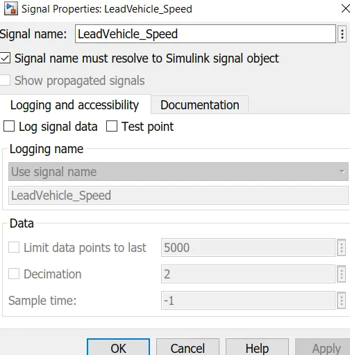
- This output signal i.e. LeadVehicle_Speed is generated in this subsystem only, hence we are resolving the same as under;
Requirement 2 – Drive Vehicle:-
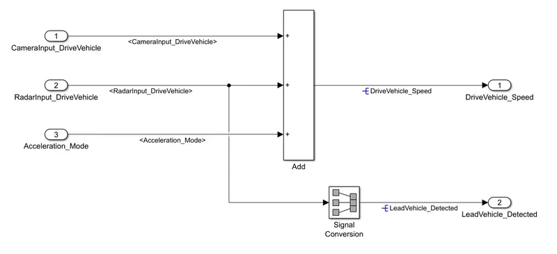
fig. 6 Drive Vehicle Subsystem
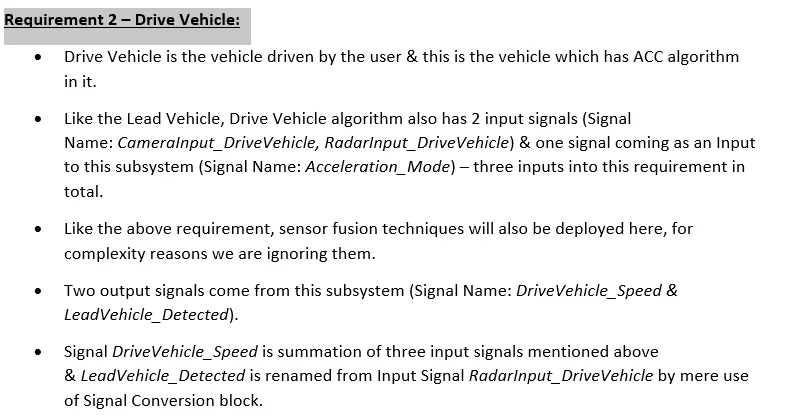
- Drive Vehicle is the vehicle driven by the user & this is the vehicle which has ACC algorithm in it.
- In the Drive Vehicle subsytem, there are total 2 input signals (Signal Name: CameraInput_DriveVehicle, RadarInput_DriveVehicle) & one signal coming as an Input to this subsystem (Signal Name: Acceleration_Mode) . It means that total 3 nos. of signals are applied as an input to Drive Vehicle Subsystem.
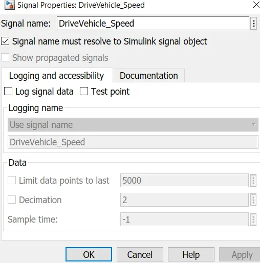
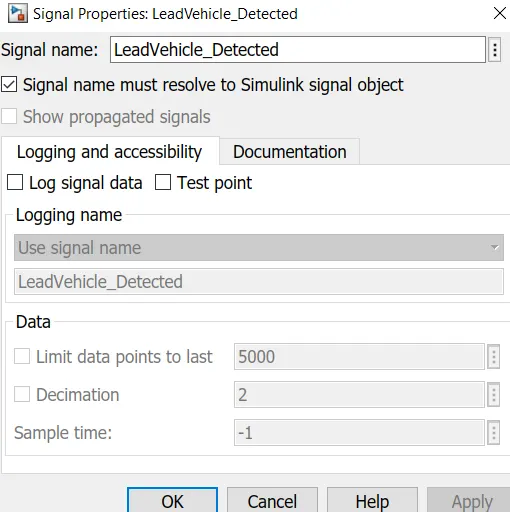
- In this, one output signal DriveVehicle_Speed is nothing but an addition of three input signals (Signal Name: CameraInput_DriveVehicle, RadarInput_DriveVehicle, Acceleration_Mode) & other output signal i.e. LeadVehicle_Detected is renamed from Input Signal i.e. RadarInput_DriveVehicle by using Signal Conversion block.
- This two output signals are then resolved as under;
Requirement 3 - Adaptive Cruise Control Algorithm :-
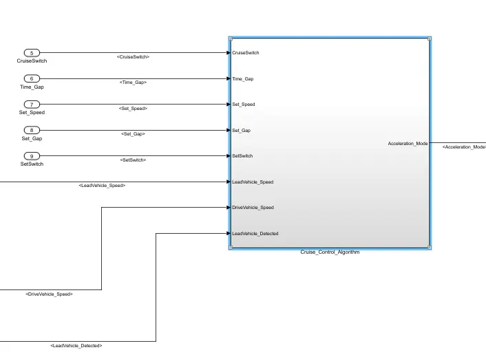
fig.7a Cruise_Control_Algorithm Subsystem
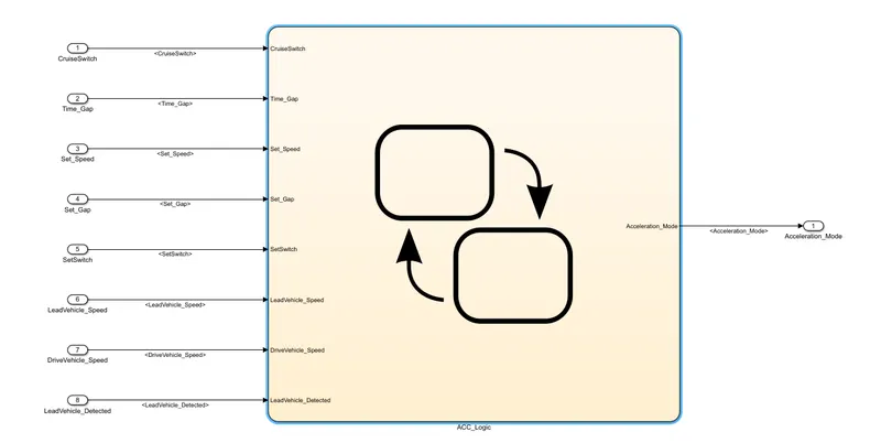
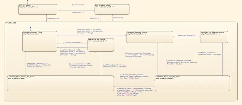
fig.7b ACC_logic of flow chart
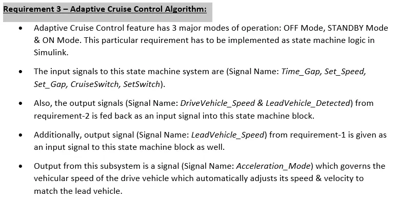
- Adaptive Cruise Control feature has 3 major modes of operation: OFF Mode, STANDBY Mode & ON Mode. This particular requirement has to be implemented as state machine logic in Simulink.
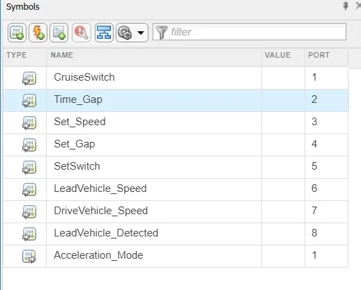
- The input signals to this state machine system are (Signal Name: Time_Gap, Set_Speed, Set_Gap, CruiseSwitch, SetSwitch).
- Also, the output signals (Signal Name: DriveVehicle_Speed & LeadVehicle_Detected) from Drive vehicle subsystem block is fed back as an input signal into this state machine block. Additionally, output signal (Signal Name: LeadVehicle_Speed) from Lead vehicle subsystem is given as an input signal to this state machine block as well.
- Output signal from this subsystem is Acceleration_Mode which governs the vehicular speed of the drive vehicle which automatically adjusts its speed & velocity to match the lead vehicle.
Requirement 3a –ACC_OFF_MODE state logic :-
- In the stateflow logic chart, ACC_OFF_MODE is the default state inside state machine logic. Output signal Acceleration_Mode is at value 0 in this state.
- This state is governed by input signal CruiseSwitch. If CruiseSwitch is equal to 1, state ACC_STANDBY_MODE will get activated.
- If CruiseSwitch is equal to 0, state ACC_OFF_MODE will get activated, from either ACC_ON_MODE or ACC_STANDBY_MODE.
Requirement 3b – ACC_STANDBY_MODE state logic :-
- This is the second activated state inside state machine logic. Output signal Acceleration_Mode is at value 1 in this state.
- This state is governed by both input signals CruiseSwitch & SetSwitch.
- If [CruiseSwitch==1], state ACC_STANDBY_MODE will get activated. If [CruiseSwitch==0], ACC_OFF_MODE state will get activated, from either ACC_ON_MODE or ACC_STANDBY_MODE.
- If [SetSwitch==1], state ACC_ON_MODE state will get activated. If [SetSwitch==0], state ACC_STANDBY_MODE will get activated.
Requirement 3c – ACC_ON_MODE state logic:
- ACC_STANDBY_MODE state goes into ACC_ON_MODE state when input signal [SetSwitch==1].
There are 6 sub states to this state logic: They are:
- LeadVehicle_Detected_Follow (Default)
- LeadVehicle_Not_Detected
- LeadVehicle_Detected_Resume
- LeadVehicle_Not_Detected_Resume
- LeadVehicle_Speed_lessthan_Set_Speed
- LeadVehicle_Speed_equal_Set_Speed
Requirement 3c (i) :– LeadVehicle_Detected_Follow (ACC_ON_MODE)
- This is the default sub state inside ACC_ON_MODE state. Output signal Acceleration_Mode is equal to 2.
- When input signal condition i.e. [LeadVehicle_Detected == 0] gets satisfied, there is a transition of state from LeadVehicle_Detected_Follow to LeadVehicle_Not_Detected.
- When input Signals condition (LeadVehicle_Detected == 1) && (LeadVehicle_Speed < Set_Speed) || (Time_Gap < Set_Gap) gets satisfied, there is a transition of state from LeadVehicle_Detected_Follow to LeadVehicle_Speed_lessthan_Set_Speed.
Requirement 3c (ii) – LeadVehicle_Not_Detected (ACC_ON_MODE)
- Output signal Acceleration_Mode is equal to 1.
- When input signals condition [(LeadVehicle_Detected==1) && (DriveVehicle_Speed == Set_Speed) && (LeadVehicle_Speed >= Set_Speed) && (Time_Gap >= Set_Gap)] gets satisifed, there is a transition of state from LeadVehicle_Not_Detected to LeadVehicle_Detected_Follow.
- When input signals condition [(LeadVehicle_Detected == 1) && (LeadVehicle_Speed < Set_Speed) || (Time_Gap < Set_Gap)] gets satisfied, there is a transition of state from LeadVehicle_Not_Detected to LeadVehicle_Speed_lessthan_Set_Speed.
Requirement 3c (iii) – LeadVehicle_Detected_Resume (ACC_ON_MODE)
- Output signal Acceleration_Mode is equal to 3.
- Condition to transit from LeadVehicle_Detected_Resume to LeadVehicle_Detected_Follow; When input signals condition [(DriveVehicle_Speed == Set_Speed) && (LeadVehicle_Speed >= Set_Speed) && (Time_Gap >= Set_Gap)] gets satisfied, there is a transition of state from LeadVehicle_Detected_Resume to LeadVehicle_Not_Detected_Resume.
- When input Signal condition [(DriveVehicle_Speed < Set_Speed) && (LeadVehicle_Speed > DriveVehicle_Speed) && (Time_Gap >= Set_Gap)] gets satisfied, there is a transition of state from LeadVehicle_Detected_Resume to LeadVehicle_Speed_equal_Set_Speed.
Requirement 3c (iv) - LeadVehicle_Not_Detected_Resume (ACC_ON_MODE)
- Output signal Acceleration_Mode is equal to 1.
Requirement 3c (v) - LeadVehicle_Speed_lessthan_Set_Speed (ACC_ON_MODE)
- Output signal Acceleration_Mode is equal to 4.
- When input Signal condition [(LeadVehicle_Detected == 0) && (DriveVehicle_Speed == Set_Speed)] gets satisfied, there is a transition of state from LeadVehicle_Speed_lessthan_Set_Speed to LeadVehicle_Not_Detected.
- When input signals condition [((LeadVehicle_Speed*1.25>=DriveVehicle_Speed) && (LeadVehicle_Speed * 0.75<=DriveVehicle_Speed)) && (DriveVehicle_Speed < Set_Speed) && ((Time_Gap<=1.25*Set_Gap) && (Time_Gap >=0.75*Set_Gap))] gets satisfied, there is a transition of state from LeadVehicle_Speed_lessthan_Set_Speed to LeadVehicle_Speed_equal_Set_Speed.
Requirement 3c (vi) - LeadVehicle_Speed_equal_Set_Speed (ACC_ON_MODE)
- Output signal Acceleration_Mode is equal to 5.
- When input signal conditions [(LeadVehicle_Detected == 0) || (DriveVehicle_Speed <= Set_Speed)] gets satisfied, there is a transition of state from LeadVehicle_Speed_equal_Set_Speed to LeadVehicle_Not_Detected_Resume.
- When input signal conditions [(DriveVehicle_Speed < Set_Speed) && (LeadVehicle_Speed > DriveVehicle_Speed) || (Time_Gap >= Set_Gap)] gets satisfied, there is a transition of state from LeadVehicle_Speed_equal_Set_Speed to LeadVehicle_Detected_Resume.
- When input signals conditions [(LeadVehicle_Speed
Further, we have defined the number of input signals and output signal required in this Simulink stateflow logic in the 'Symbol Pane' option as under;
Changes in Configuration Parameters :-
We have changed the configuration parameters by firstly changing the solver settings by clicking on 'Model Settings'. After opening the 'Model Settings', converting the type as fixed step and solver as discrete (no continous)and changed the sample time as 0.01 sec.
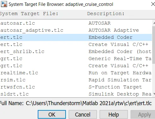
Then, we have changed the System Target File to 'ert.tlc' under code generation section as under;
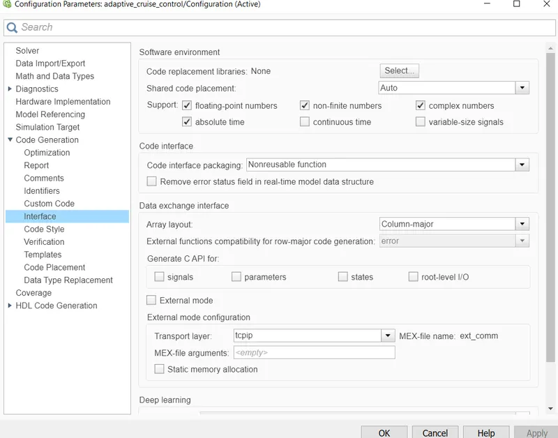
Further, in the configuration parameter under Code generation settings, we have select 'floating point number' checkbox as under;
Creation of Simulink Data Dictionary (SLDD) File :-
A Simulink Data Dictionary (SLDD) file is created so that it contains input, output signals and caliberation parameters used in the given model instead of using Init file for initilalizing caliberation values everytime.
Step 1 :-
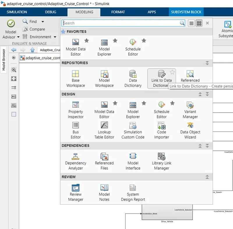
We have to go under Modelling section and select on 'Link to Data Dictionary' as under;
Step 2 :-
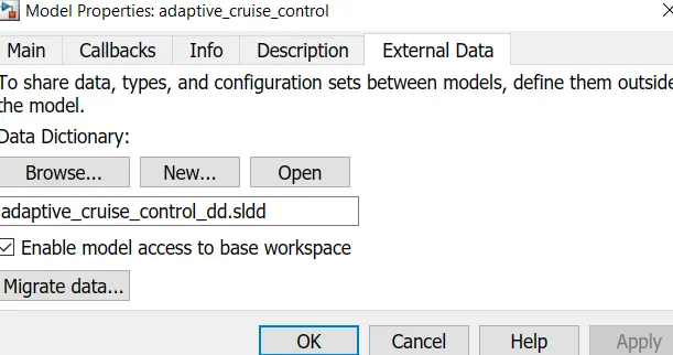
Create a new data directory in the given folder and named it by giving .sldd extension.
Step 3 :-
We have been given the input signal, output signal and Caliberation values/ constant and the same are as under;
|
Signal / Calibration Name |
Signal Type |
Data Type |
Dimension |
Min |
Max |
Initial Value |
Units |
|
CameraInput_LeadVehicle |
Input |
Uint8 |
1 |
0 |
255 |
- |
- |
|
RadarInput_LeadVehicle |
Input |
Uint8 |
1 |
0 |
255 |
- |
- |
|
CameraInput_DriveVehicle |
Input |
Uint8 |
1 |
0 |
255 |
- |
- |
|
RadarInput_DriveVehicle |
Input |
Uint8 |
1 |
0 |
255 |
- |
- |
|
Time_Gap |
Input |
Uint8 |
1 |
0 |
255 |
- |
- |
|
Set_Speed |
Input |
Uint8 |
1 |
0 |
255 |
- |
- |
|
Set_Gap |
Input |
Uint8 |
1 |
0 |
255 |
- |
- |
|
CruiseSwitch |
Input |
Boolean |
1 |
0 |
1 |
- |
- |
|
SetSwitch |
Input |
Boolean |
1 |
0 |
1 |
- |
- |
|
Acceleration_Mode |
Output |
Uint8 |
1 |
0 |
255 |
- |
- |
|
LeadVehicle_Speed |
Output |
Uint8 |
1 |
0 |
255 |
- |
- |
|
DriveVehicle_Speed |
Output |
Uint8 |
1 |
0 |
255 |
- |
- |
|
LeadVehicle_Detected |
Output |
Uint8 |
1 |
0 |
255 |
- |
- |
Accordingly, we have created the Simulink Data Dictionary (SLDD) by clicking on file name i.e adaptive_cruise_control_dd.sldd and select Design data. Then, we have to select add signal and add simulink parameter depending on whether the values are input signal, output signal or constant/caliberation values
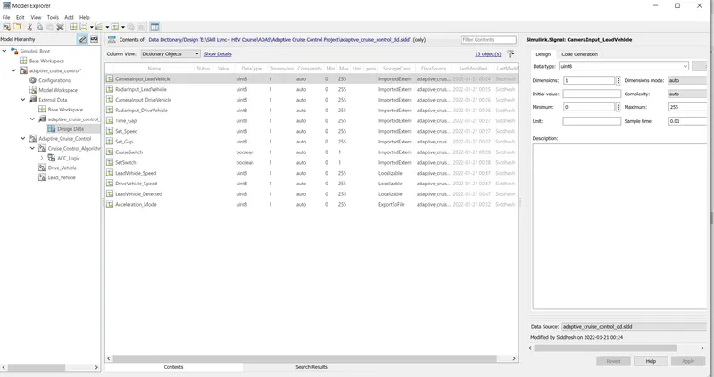
- In this, we have chose the Storage class for Input signals as ImportedExtern; Storage class for Output signal as Export to File; Storage class for local signals as localizable; Storage class for calibration signals as Const.
- Sample time for all signals are taken as 0.01 sec as per given condition.
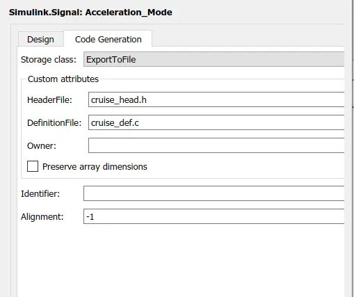
- While declaring output signal and constant values, we have given header file name as 'cruise_head.h' and definition file name as 'cruise_def.c'. The same is as under;
Requirement Tagging of Simulink Model:-
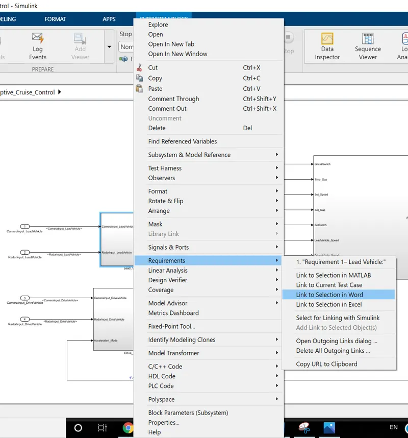
The requirements ‘Requirement 1’ , ‘Requirement 2’ , and ‘Requirement 3’ as provided in the Requirements Word document are tagged to their corresponding subsystem in the Simulink Model.
Steps for tagging a requirement in Simulink model :-
- First, we have highlight/ select the requirement statement in the Word document file. This word document file needs to be same MATLAB path.
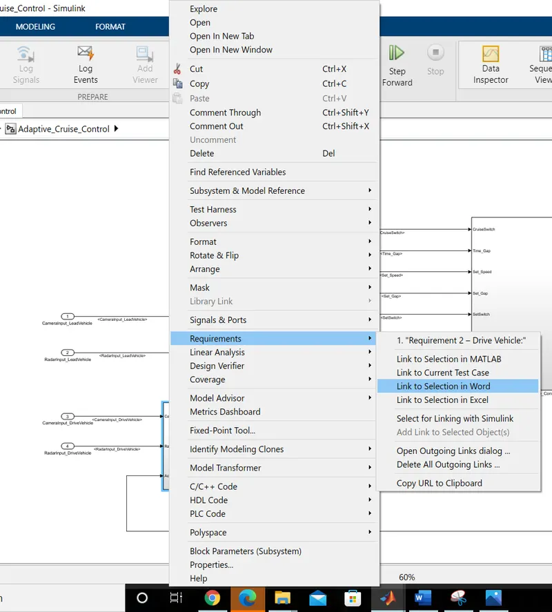
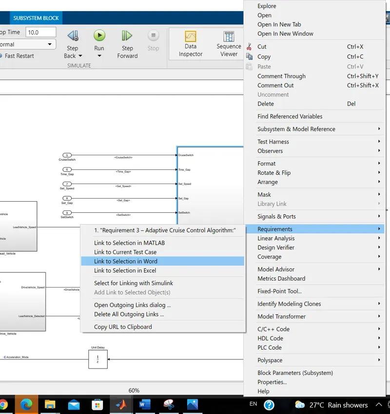
- Then, we have to go in Simulink Model and right click on particular subsystem, we need to tag. After right clicking, we have to select 'Requirements' and then click on 'link to Selection in word'. Then, the particular subsytem will get tagged for the highlighted text on word documents file.
- After doing sucessful tagging, MATLAB traceability file is generated in the same MATLAB path.
We have considered above steps while tagging the Requirement1,Requirement2 and Requirement3 and the same are as under;
Tagging for Requirement - 1 (Lead Vehicle):-

Tagging for Requirement - 2 (Drive Vehicle):-
Tagging for Requirement -3 Adaptive Cruise Control Algorithm:-
After successful tagging for requirements 1, requirements 2 and requirements 3, we observed that Matlab Traceability file is automatically generated in the same Matlab folder path. (The same is attached)
Steps for Checking MAB Guidelines :-
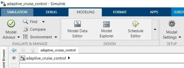
Step 1:-
We have to go into 'Modelling option' and then select 'Model Advisor'
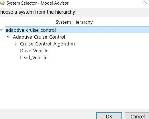
Step 2:-
We have to choose the system for checking guidelines. In this case, we are checking full system check as under as per MAB guidelines;
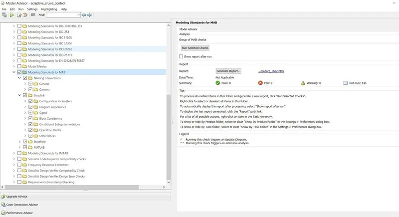
Step 3 :-
Therafter, below screen appears. In this, we have to select as per Modelling standards for MAB guidelines.
Then, we have to click on 'Run Selected Check' option as under;
After running the model as per MAB Guidelines, we observed that it is sucessfully passed with value of 120 and total 24 nos. of warnings. However, there is no fail condition. Hence, we can conclude that above model is technically/logically correct.
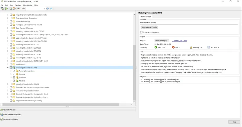
After successful running of model as per MAB guidelines, we observed that guideline report is generated in the same Matlab folder path. (The same is attached)
Steps for Generation of Code from model:-
Step 1 :-
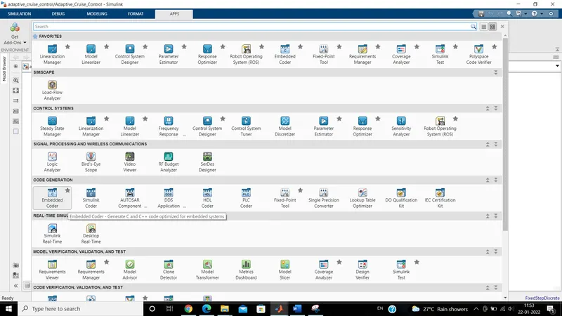
Go to Apps section and under Code Generation section, select Embedded Coder option.
Step 2 :-
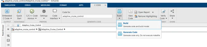
Then, under Embedded C Code section, Click on Generate Code option as under;
Step 3 :-
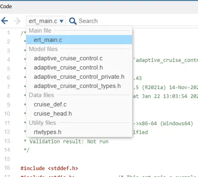
In the generation of code, there is one main c file, 4 nos. of model files, 2 data files, 1 one utility file is generated as under;
After sucessful completion of Code generation, adaptive_cruise_control_ert_rtw folder is created in the Matlab path as under;

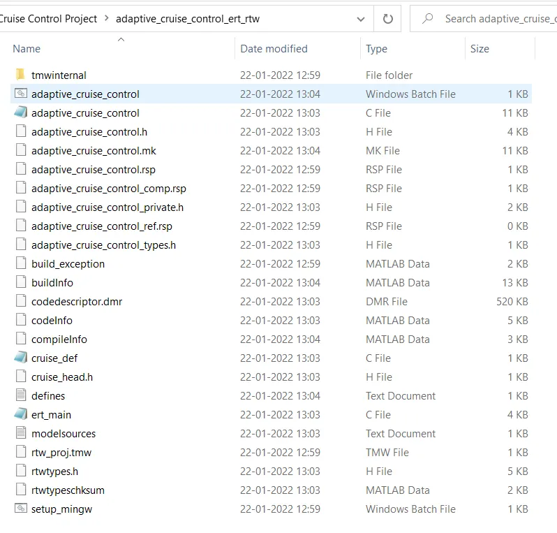
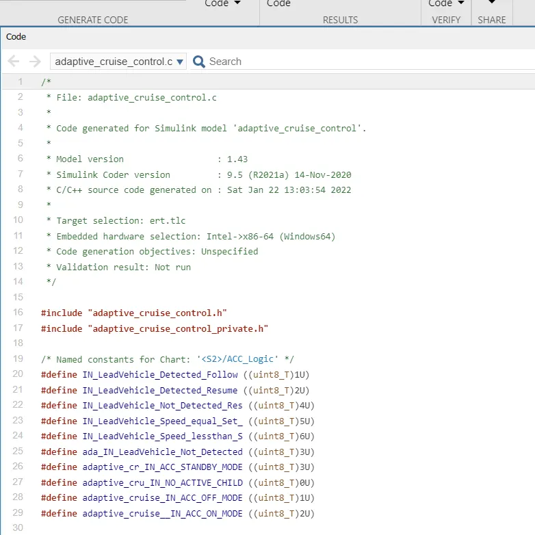
The Generated C code for adaptive_cruise_control.c file is as under;
C Code :-
/*
 * File: adaptive_cruise_control.c
 *
 * Code generated for Simulink model 'adaptive_cruise_control'.
 *
 * Model version                  : 1.43
 * Simulink Coder version         : 9.5 (R2021a) 14-Nov-2020
 * C/C++ source code generated on : Sat Jan 22 13:03:54 2022
 *
 * Target selection: ert.tlc
 * Embedded hardware selection: Intel->x86-64 (Windows64)
 * Code generation objectives: Unspecified
 * Validation result: Not run
 */

#include "adaptive_cruise_control.h"
#include "adaptive_cruise_control_private.h"

/* Named constants for Chart: '/ACC_Logic' */
#define IN_LeadVehicle_Detected_Follow ((uint8_T)1U)
#define IN_LeadVehicle_Detected_Resume ((uint8_T)2U)
#define IN_LeadVehicle_Not_Detected_Res ((uint8_T)4U)
#define IN_LeadVehicle_Speed_equal_Set_ ((uint8_T)5U)
#define IN_LeadVehicle_Speed_lessthan_S ((uint8_T)6U)
#define ada_IN_LeadVehicle_Not_Detected ((uint8_T)3U)
#define adaptive_cr_IN_ACC_STANDBY_MODE ((uint8_T)3U)
#define adaptive_cru_IN_NO_ACTIVE_CHILD ((uint8_T)0U)
#define adaptive_cruise_IN_ACC_OFF_MODE ((uint8_T)1U)
#define adaptive_cruise__IN_ACC_ON_MODE ((uint8_T)2U)

/* Block states (default storage) */
DW_adaptive_cruise_control_T adaptive_cruise_control_DW;

/* External outputs (root outports fed by signals with default storage) */
ExtY_adaptive_cruise_control_T adaptive_cruise_control_Y;

/* Real-time model */
static RT_MODEL_adaptive_cruise_cont_T adaptive_cruise_control_M_;
RT_MODEL_adaptive_cruise_cont_T *const adaptive_cruise_control_M =
  &adaptive_cruise_control_M_;
real_T rt_roundd_snf(real_T u)
{
  real_T y;
  if (fabs(u) < 4.503599627370496E+15) {
    if (u >= 0.5) {
      y = floor(u + 0.5);
    } else if (u > -0.5) {
      y = u * 0.0;
    } else {
      y = ceil(u - 0.5);
    }
  } else {
    y = u;
  }

  return y;
}

/* Model step function */
void adaptive_cruise_control_step(void)
{
  /* local block i/o variables */
  uint8_T LeadVehicle_Speed;
  uint8_T DriveVehicle_Speed;
  uint8_T LeadVehicle_Detected;
  int32_T tmp;
  int32_T tmp_0;
  uint8_T tmp_1;
  uint8_T tmp_2;

  /* Sum: '/Add' incorporates:
   *  Inport: '/CameraInput_LeadVehicle'
   *  Inport: '/RadarInput_LeadVehicle'
   */
  LeadVehicle_Speed = (uint8_T)((uint32_T)CameraInput_LeadVehicle +
    RadarInput_LeadVehicle);

  /* UnitDelay: '/Unit Delay' */
  Acceleration_Mode = adaptive_cruise_control_Y.Acceleration_Mode_h;

  /* Sum: '/Add' incorporates:
   *  Inport: '/CameraInput_DriveVehicle'
   *  Inport: '/RadarInput_DriveVehicle'
   */
  DriveVehicle_Speed = (uint8_T)((uint32_T)(uint8_T)((uint32_T)
    CameraInput_DriveVehicle + RadarInput_DriveVehicle) + Acceleration_Mode);

  /* SignalConversion: '/Signal Conversion' incorporates:
   *  Inport: '/RadarInput_DriveVehicle'
   */
  LeadVehicle_Detected = RadarInput_DriveVehicle;

  /* Chart: '/ACC_Logic' incorporates:
   *  Inport: '/CruiseSwitch'
   *  Inport: '/SetSwitch'
   *  Inport: '/Set_Gap'
   *  Inport: '/Set_Speed'
   *  Inport: '/Time_Gap'
   *  UnitDelay: '/Unit Delay'
   */
  if (adaptive_cruise_control_DW.is_active_c3_adaptive_cruise_co == 0U) {
    adaptive_cruise_control_DW.is_active_c3_adaptive_cruise_co = 1U;
    adaptive_cruise_control_DW.is_c3_adaptive_cruise_control =
      adaptive_cruise_IN_ACC_OFF_MODE;
    adaptive_cruise_control_Y.Acceleration_Mode_h = 0U;
  } else {
    switch (adaptive_cruise_control_DW.is_c3_adaptive_cruise_control) {
     case adaptive_cruise_IN_ACC_OFF_MODE:
      adaptive_cruise_control_Y.Acceleration_Mode_h = 0U;
      if (CruiseSwitch) {
        adaptive_cruise_control_DW.is_c3_adaptive_cruise_control =
          adaptive_cr_IN_ACC_STANDBY_MODE;
        adaptive_cruise_control_Y.Acceleration_Mode_h = 1U;
      }
      break;

     case adaptive_cruise__IN_ACC_ON_MODE:
      if (!CruiseSwitch) {
        adaptive_cruise_control_DW.is_ACC_ON_MODE =
          adaptive_cru_IN_NO_ACTIVE_CHILD;
        adaptive_cruise_control_DW.is_c3_adaptive_cruise_control =
          adaptive_cruise_IN_ACC_OFF_MODE;
        adaptive_cruise_control_Y.Acceleration_Mode_h = 0U;
      } else if (!SetSwitch) {
        adaptive_cruise_control_DW.is_ACC_ON_MODE =
          adaptive_cru_IN_NO_ACTIVE_CHILD;
        adaptive_cruise_control_DW.is_c3_adaptive_cruise_control =
          adaptive_cr_IN_ACC_STANDBY_MODE;
        adaptive_cruise_control_Y.Acceleration_Mode_h = 1U;
      } else {
        switch (adaptive_cruise_control_DW.is_ACC_ON_MODE) {
         case IN_LeadVehicle_Detected_Follow:
          adaptive_cruise_control_Y.Acceleration_Mode_h = 2U;
          if (LeadVehicle_Detected == 0) {
            adaptive_cruise_control_DW.is_ACC_ON_MODE =
              ada_IN_LeadVehicle_Not_Detected;
            adaptive_cruise_control_Y.Acceleration_Mode_h = 1U;
          } else if (((LeadVehicle_Detected == 1) && (LeadVehicle_Speed <
                       Set_Speed)) || (Time_Gap < Set_Gap)) {
            adaptive_cruise_control_DW.is_ACC_ON_MODE =
              IN_LeadVehicle_Speed_lessthan_S;
            adaptive_cruise_control_Y.Acceleration_Mode_h = 4U;
          }
          break;

         case IN_LeadVehicle_Detected_Resume:
          adaptive_cruise_control_Y.Acceleration_Mode_h = 3U;
          if (LeadVehicle_Detected == 0) {
            adaptive_cruise_control_DW.is_ACC_ON_MODE =
              IN_LeadVehicle_Not_Detected_Res;
            adaptive_cruise_control_Y.Acceleration_Mode_h = 1U;
          } else if ((DriveVehicle_Speed == Set_Speed) && (LeadVehicle_Speed >=
                      Set_Speed) && (Time_Gap >= Set_Gap)) {
            adaptive_cruise_control_DW.is_ACC_ON_MODE =
              IN_LeadVehicle_Detected_Follow;
            adaptive_cruise_control_Y.Acceleration_Mode_h = 2U;
          } else if ((DriveVehicle_Speed < Set_Speed) && (LeadVehicle_Speed >
                      DriveVehicle_Speed) && (Time_Gap >= Set_Gap)) {
            adaptive_cruise_control_DW.is_ACC_ON_MODE =
              IN_LeadVehicle_Speed_equal_Set_;
            adaptive_cruise_control_Y.Acceleration_Mode_h = 5U;
          }
          break;

         case ada_IN_LeadVehicle_Not_Detected:
          adaptive_cruise_control_Y.Acceleration_Mode_h = 1U;
          if ((LeadVehicle_Detected == 1) && (DriveVehicle_Speed == Set_Speed) &&
              (LeadVehicle_Speed >= Set_Speed) && (Time_Gap >= Set_Gap)) {
            adaptive_cruise_control_DW.is_ACC_ON_MODE =
              IN_LeadVehicle_Detected_Follow;
            adaptive_cruise_control_Y.Acceleration_Mode_h = 2U;
          } else if (((LeadVehicle_Detected == 1) && (LeadVehicle_Speed <
                       Set_Speed)) || (Time_Gap < Set_Gap)) {
            adaptive_cruise_control_DW.is_ACC_ON_MODE =
              IN_LeadVehicle_Speed_lessthan_S;
            adaptive_cruise_control_Y.Acceleration_Mode_h = 4U;
          }
          break;

         case IN_LeadVehicle_Not_Detected_Res:
          adaptive_cruise_control_Y.Acceleration_Mode_h = 1U;
          break;

         case IN_LeadVehicle_Speed_equal_Set_:
          adaptive_cruise_control_Y.Acceleration_Mode_h = 5U;
          if ((LeadVehicle_Detected == 0) || (DriveVehicle_Speed <= Set_Speed))
          {
            adaptive_cruise_control_DW.is_ACC_ON_MODE =
              IN_LeadVehicle_Not_Detected_Res;
            adaptive_cruise_control_Y.Acceleration_Mode_h = 1U;
          } else if (((DriveVehicle_Speed < Set_Speed) && (LeadVehicle_Speed >
                       DriveVehicle_Speed)) || (Time_Gap >= Set_Gap)) {
            adaptive_cruise_control_DW.is_ACC_ON_MODE =
              IN_LeadVehicle_Detected_Resume;
            adaptive_cruise_control_Y.Acceleration_Mode_h = 3U;
          } else if (((LeadVehicle_Speed < Set_Speed) && (LeadVehicle_Speed <
                       DriveVehicle_Speed)) || ((int32_T)rt_roundd_snf(0.75 *
                       (real_T)Set_Gap) == Time_Gap)) {
            adaptive_cruise_control_DW.is_ACC_ON_MODE =
              IN_LeadVehicle_Speed_lessthan_S;
            adaptive_cruise_control_Y.Acceleration_Mode_h = 4U;
          }
          break;

         default:
          /* case IN_LeadVehicle_Speed_lessthan_Set_Speed: */
          adaptive_cruise_control_Y.Acceleration_Mode_h = 4U;
          if ((LeadVehicle_Detected == 0) && (DriveVehicle_Speed == Set_Speed))
          {
            adaptive_cruise_control_DW.is_ACC_ON_MODE =
              ada_IN_LeadVehicle_Not_Detected;
            adaptive_cruise_control_Y.Acceleration_Mode_h = 1U;
          } else {
            tmp = (int32_T)rt_roundd_snf((real_T)LeadVehicle_Speed * 1.25);
            tmp_0 = (int32_T)rt_roundd_snf(1.25 * (real_T)Set_Gap);
            if (tmp < 256) {
              tmp_1 = (uint8_T)tmp;
            } else {
              tmp_1 = MAX_uint8_T;
            }

            if (tmp_0 < 256) {
              tmp_2 = (uint8_T)tmp_0;
            } else {
              tmp_2 = MAX_uint8_T;
            }

            if ((tmp_1 >= DriveVehicle_Speed) && ((int32_T)rt_roundd_snf((real_T)
                  LeadVehicle_Speed * 0.75) <= DriveVehicle_Speed) &&
                (DriveVehicle_Speed < Set_Speed) && (Time_Gap <= tmp_2) &&
                (Time_Gap >= (int32_T)rt_roundd_snf(0.75 * (real_T)Set_Gap))) {
              adaptive_cruise_control_DW.is_ACC_ON_MODE =
                IN_LeadVehicle_Speed_equal_Set_;
              adaptive_cruise_control_Y.Acceleration_Mode_h = 5U;
            }
          }
          break;
        }
      }
      break;

     default:
      /* case IN_ACC_STANDBY_MODE: */
      adaptive_cruise_control_Y.Acceleration_Mode_h = 1U;
      if (!CruiseSwitch) {
        adaptive_cruise_control_DW.is_c3_adaptive_cruise_control =
          adaptive_cruise_IN_ACC_OFF_MODE;
        adaptive_cruise_control_Y.Acceleration_Mode_h = 0U;
      } else if (SetSwitch) {
        adaptive_cruise_control_DW.is_c3_adaptive_cruise_control =
          adaptive_cruise__IN_ACC_ON_MODE;
        adaptive_cruise_control_DW.is_ACC_ON_MODE =
          IN_LeadVehicle_Detected_Follow;
        adaptive_cruise_control_Y.Acceleration_Mode_h = 2U;
      }
      break;
    }
  }

  /* End of Chart: '/ACC_Logic' */
}

/* Model initialize function */
void adaptive_cruise_control_initialize(void)
{
  /* (no initialization code required) */
}

/* Model terminate function */
void adaptive_cruise_control_terminate(void)
{
  /* (no terminate code required) */
}

/*
 * File trailer for generated code.
 *
 * [EOF]
 */