Project 1- Traffic Jam Assistant Feature
Aim :- Traffic Jam Assistant Feature
Objective :-
- This model must be developed in MATLAB Simulink as per MBD guidelines according to the requirements given.
- Tag the requirements to the Simulink model, Requirements 1 & Requirement 2 are tagged into their corresponding subsystems.
- Creation of Simulink Data Dictionary for the model & must be linked to the model.
- Tagging for Requirement 1 and Requirement2 subsystem.
- Creation of Model Advisor Report for given Traffic Jam Assistant Feature model.
- Code Generation Profile must be in Embedded Coder.
Theory on Traffic Jam Assistant Feature :-
- Traffic Jam Assistant is one of the most common feature in Advanced Driver Assistance System.
- Traffic Jam Assist feature brakes and accelerates the car for the driver, while maintaining a safe distance from the vehicle in front.
- Traffic Jam Assistant helps the driver arrive more relaxed at their destination, even in dense traffic or in traffic jams. As a partially automated comfort function, the system takes over the longitudinal & lateral guidance of the vehicle. This means that the car can drive off, accelerate & brake automatically, as well as steer the vehicle within certain constraints.
- The driver has to permanently supervise the system & be ready to take over the complete control of the vehicle at any time.
- Traffic Jam Assistant system helps to avoid rear end collisions in dense traffic conditions & traffic jams. In Traffic jams, the vehicle takes over driving off, acceleration, braking and steering within same lane.
Working Principle of Traffic Jam Assistant Feature :
- Traffic Jam Assistant is based on the sensors and the functionality of the Adaptive Cruise Control (ACC) with stop & go and Lane Keeping Support (LKS).
- Traffic Jam Assistance (TJA) is an advanced driver assistance system that continuously measures the speed of the surrounding vehicles when Adaptive Cruise Control is switched on, then it compares with the own driving speed.
- If the system detects heavy traffic or a dense traffic jam at speeds less than 60 kmph, the driver can activate the functionality by press of a button.
- The vehicle will now automatically follow the vehicle in front by keeping the safe distance by taking over driving off, acceleration, braking and steering within same lane.
- Information regarding the Traffic Jam Assistant will be available to be displayed to the driver in the Instrument Panel Cluster (IPC).
- However, the driver needs to constantly supervise the system & be ready to take over the complete control of the vehicle when situation demands.
Development of Traffic Jam Assistant Feature :-
- One specific requirement of Traffic Jam Assistant algorithm is developed which would predominantly feature in the Instrument Panel Cluster (IPC) algorithm.
- We aware that whole actual Traffic Jam Assistant is a huge algorithm and only one small part of this logic is implemented in the below model. The idea is to familiarize with concepts of Model Based Development in MATLAB Environment. The model is implemented according to the following requirements:
Main Model :-
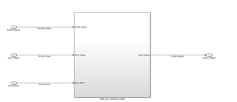
fig. Traffic Jam Assistance Model
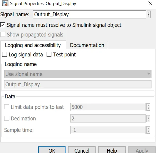
- The above model is the main model of the Traffic Jam Assistance Model logic. Here, as per given conditon, input signals to this system are Input_Switch,Enable_Display,Input_Voltage. Since, three signals are originating/used for first time, hence we have to resolve this signals by right clicking on signal properties and check the first box as under;
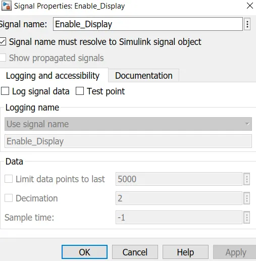
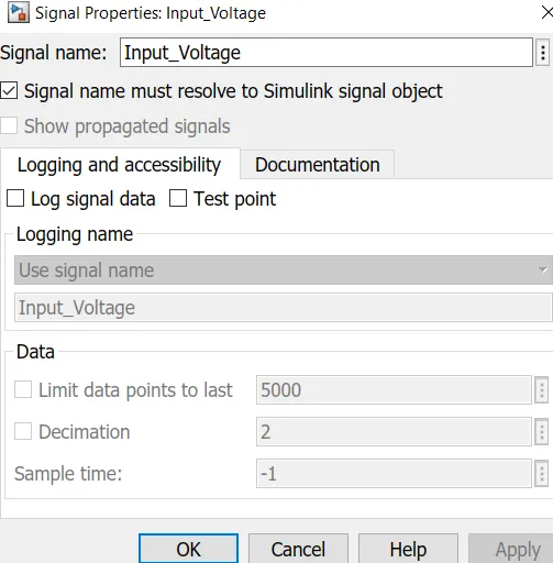
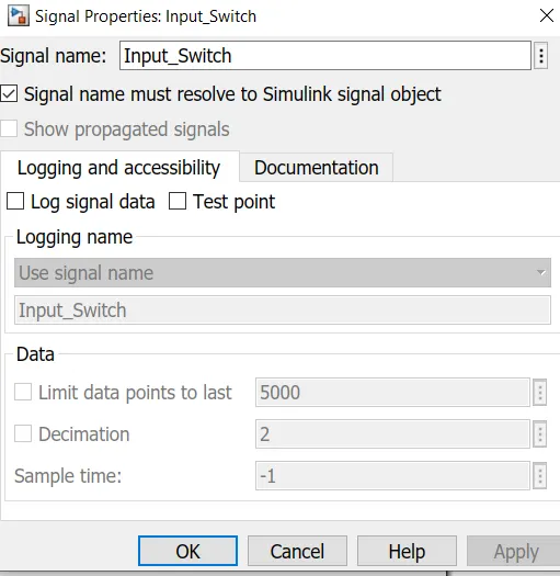
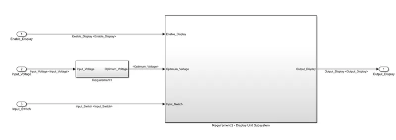
Fig. 2 Requirement 1 & Requirement2 Subsystem
- As the subsystem 'traffic_jam_assistance_model' is the main subsystem, hence it is further divided into two more subsystems as this subystems needs to follow two given requirements i.e. Requirement1 & Requirement2 subsystem.
- In this, Enable_Display & Input_Switch signal are connected as input to Requirement2 subsystem of Display unit. Further, Input_Voltage which is provided to Requirement 1 subsystem where incoming Input_Voltage signal is compared with VOLTAGE_MINIMUM_RANGE and VOLTAGE_MAXIMUM_RANGE. Further as per the logic, Optimum_Voltage value is calculated and then given to Requirement2 subsystem of Display unit as input.
- Then, in Requirement2 subsytem of Display unit, all three input signals such as Input_Switch,Enable_Display,Input_Voltage are given. In this, we have saturatedd the Enable_Display signal from values between 0 & 7. Then, the signal is given to control port.
- Then, caliberation signal ON_MODE is connected to 1st & 2nd port of multiport switch. The caliberation signal OFF_MODE is connected to 3rd & 4th port of multiport switch. Also, STANDBY_MODE is connected to 5th port of multiport switch. The output port of this multiport switch is further connected to port 1 of normal switch.
- NOT operation is performed for boolean value of input signal Input_Switch. Also, caliberation signal “INTERRUPT_1” & “INTERRUPT_2” are compared for equal to (==) operator. If the values for both is same then it will given boolean value of 1 or logical true otherwise false. The output from this equal to (==) block, NOT operation of Input_Switch is compared with Optimum_Voltage value for AND operation.
- The output from this AND operation is used as control port to operate the switch. If the o/p value is greater than 0 then port 1 of the switch will pass as output signal Output_Display and if o/p value is less than 0 then port 2 of switch in which NO_DISPLAY signal is stored will pass as Output_Display.
Requirement no.1 Subsystem :-
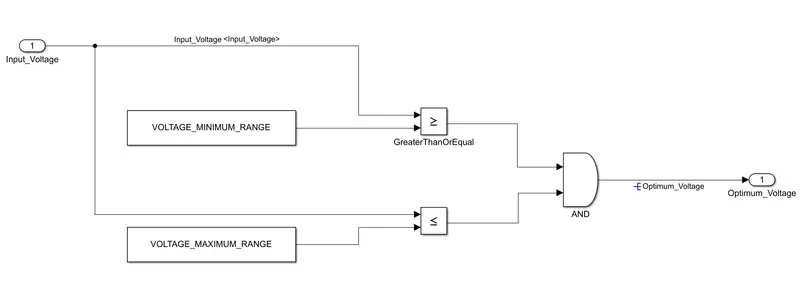
Fig.3 Requirement 1 subsystem
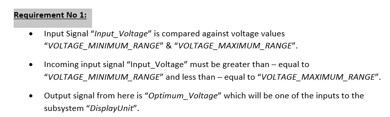
- Input Signal “Input_Voltage” is compared against voltage values “VOLTAGE_MINIMUM_RANGE” & “VOLTAGE_MAXIMUM_RANGE”.
- Incoming input signal “Input_Voltage” must be greater than – equal to “VOLTAGE_MINIMUM_RANGE” and less than – equal to “VOLTAGE_MAXIMUM_RANGE”.
- Output signal from here is “Optimum_Voltage” which will be one of the inputs to the subsystem “DisplayUnit”.
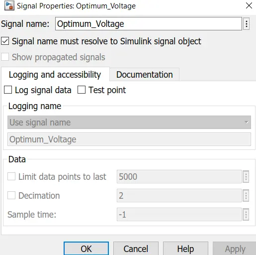
- However, output signal (i.e Optimum_Voltage) is form newly in this subsystem hence we resolve this signal by right clicking on signal properties,
Requirement No 2 (DisplayUnit Subsystem):
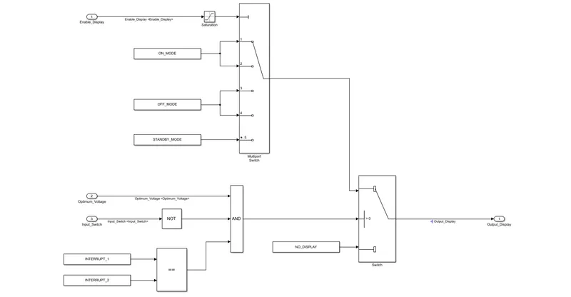
Fig.4 Requirement 2 subsystem
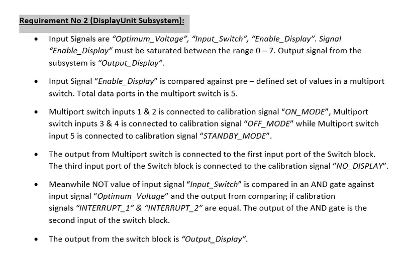
- Input Signals are “Optimum_Voltage”, “Input_Switch”,“Enable_Display”. Signal “Enable_Display” must be saturated between the range 0 – 7 as under;
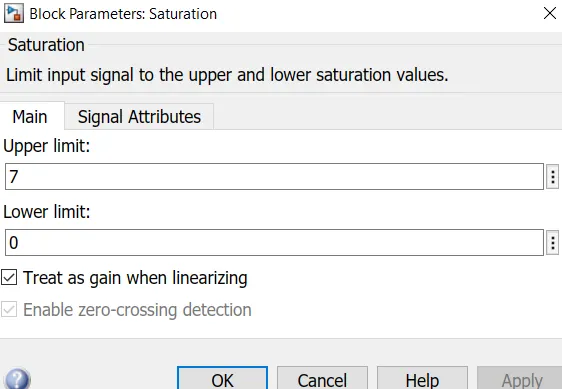
- Output signal from this Requirement 2 subsystem is “Output_Display”.
- Input Signal “Enable_Display” is compared against pre – defined set of values in a multiport switch. Total data ports in the multiport switch is 5.
- Multiport switch inputs 1 & 2 is connected to calibration signal “ON_MODE”, Multiport switch inputs 3 & 4 is connected to calibration signal “OFF_MODE” while Multiport switch input 5 is connected to calibration signal “STANDBY_MODE”.
- The output from Multiport switch is connected to the first input port of the Switch block. The third input port of the Switch block is connected to the calibration signal “NO_DISPLAY”.
- Meanwhile NOT value of input signal “Input_Switch” is compared in an AND gate against input signal “Optimum_Voltage” and the output from comparing if calibration signals “INTERRUPT_1” & “INTERRUPT_2” are equal. The output of the AND gate is the second input of the switch block.
- The output from the switch block is “Output_Display”.
- However, output signal (i.e Output_Display) is form newly in this subsystem hence we resolve this signal by right clicking on signal properties,
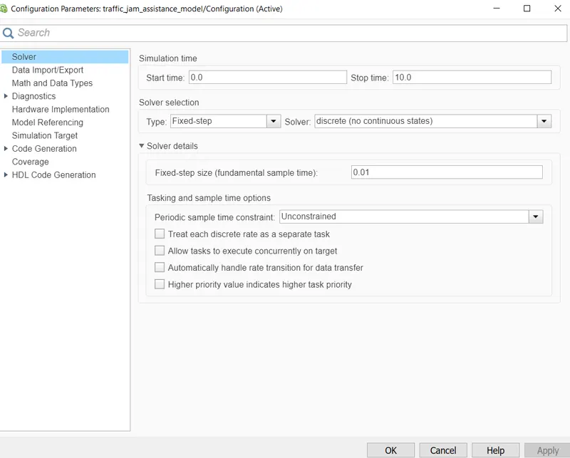
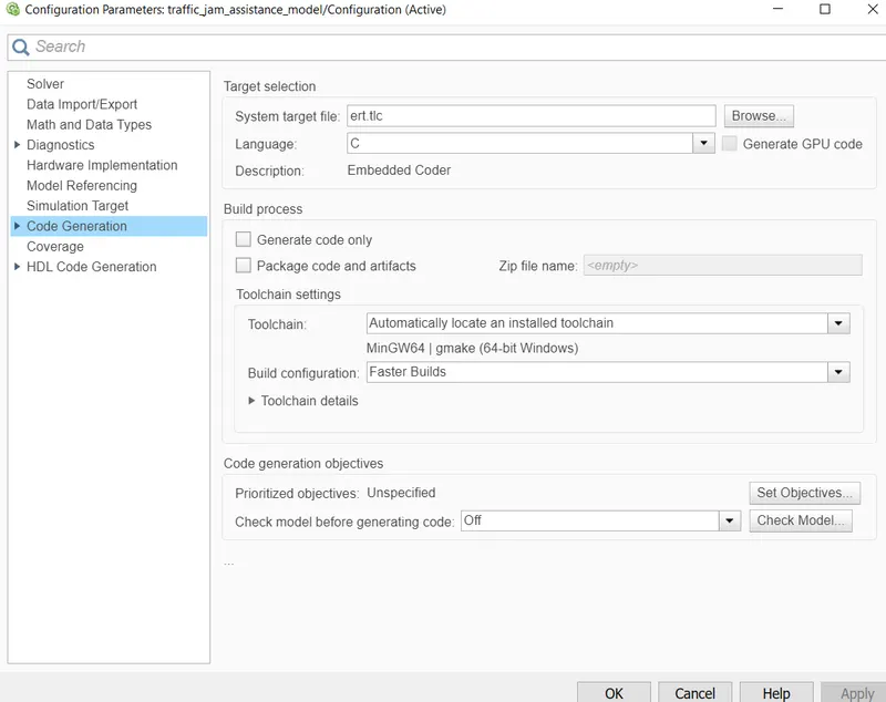
Then, we have changed the configuration parameters by firstly, changed the solver settings by clicking on 'Model Settings'. After opening the 'Model Settings', converting the type as fixed step and solver as discrete (no continous)and changed the sample time as 0.01 sec.
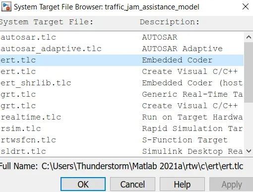
Then, we have changed the System Target File to 'ert.tlc' under code generation section as under;
Creation of Simulink Data Dictonary :-
-
A Simulink Data Dictionary (SLDD) file is created so that it contains input, output signals and caliberation parameters used in the given model instead of using Init file for initilalizing caliberation values everytime.
Step 1 :-
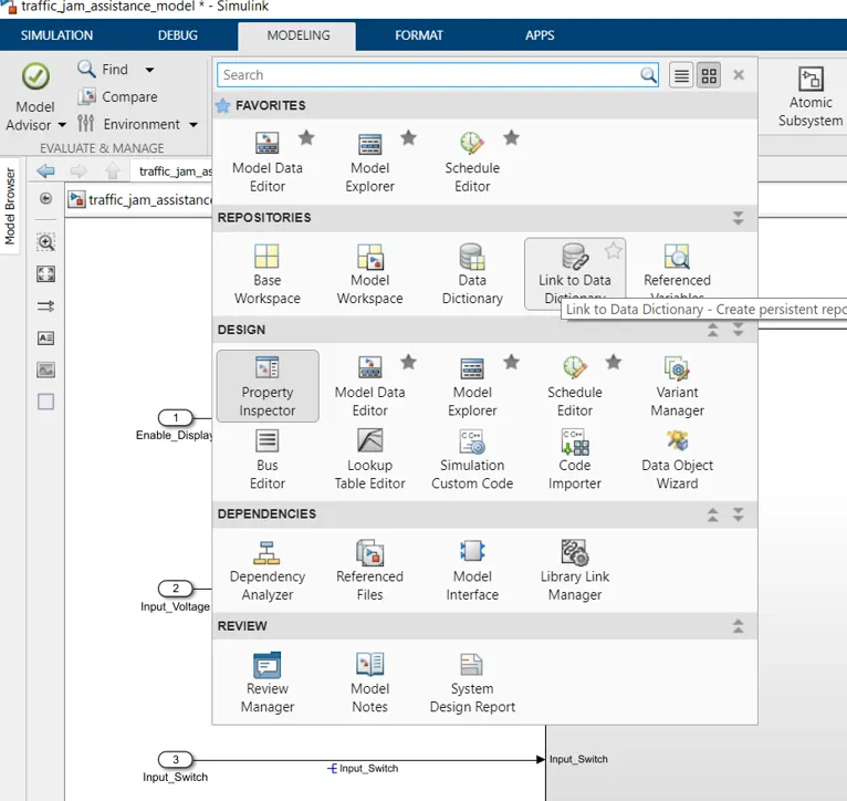
We have to go under Modelling section and select on 'Link to Data Dictionary' as under;
Step 2 :-
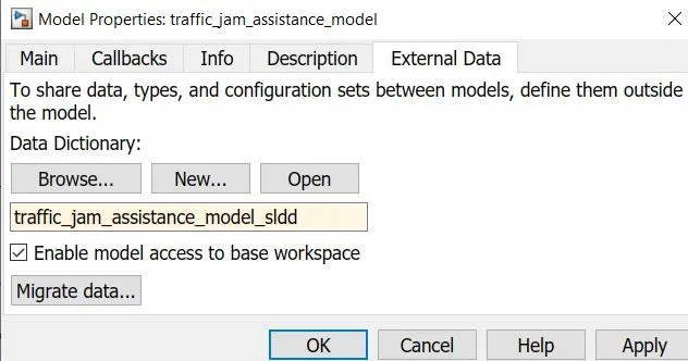
Create a new data directory in the given folder and named it by giving .sldd extension.
Step 3 :-
We have given the input signal, output signal and Caliberation values/ constant and the same are as under;
Input Signals:
|
Name of the Signal |
Data Type |
Range |
|
Input_Voltage |
uint8 |
0 - 255 |
|
Input_Switch |
boolean |
0 – 1 |
|
Enable_Display |
uint8 |
0 - 255 |
Output Signal:
|
Name of the Signal |
Data Type |
Range |
|
Output_Display |
uint8 |
0 - 255 |
Calibration Signals:
|
Name of the Signal |
Data Type |
Range |
Initial Value |
|
VOLTAGE_MINIMUM_RANGE |
uint8 |
0 – 255 |
30 |
|
VOLTAGE_MAXIMUM_RANGE |
uint8 |
0 – 255 |
50 |
|
OFF_MODE |
uint8 |
0 – 255 |
2 |
|
ON_MODE |
uint8 |
0 – 255 |
1 |
|
STANDBY_MODE |
uint8 |
0 – 255 |
3 |
|
INTERRUPT_1 |
boolean |
0 – 1 |
1 |
|
INTERRUPT_2 |
boolean |
0 - 1 |
1 |
|
NO_DISPLAY |
uint8 |
0 – 255 |
0 |
Local Signal:
|
Name of the Signal |
Data Type |
Range |
|
Optimum_Voltage |
boolean |
0 - 1 |
Accordingly, we have created the Simulink Data Dictionary (SLDD) by clicking on file name i.e traffic_jam_assistance_model_sldd.sldd and select Design data. Then, we have to select add signal and add simulink parameter depending on whether the values are input signal, output signal or constant/caliberation values.
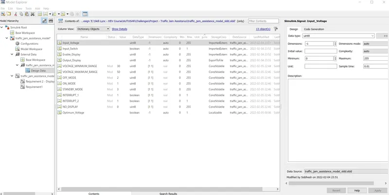
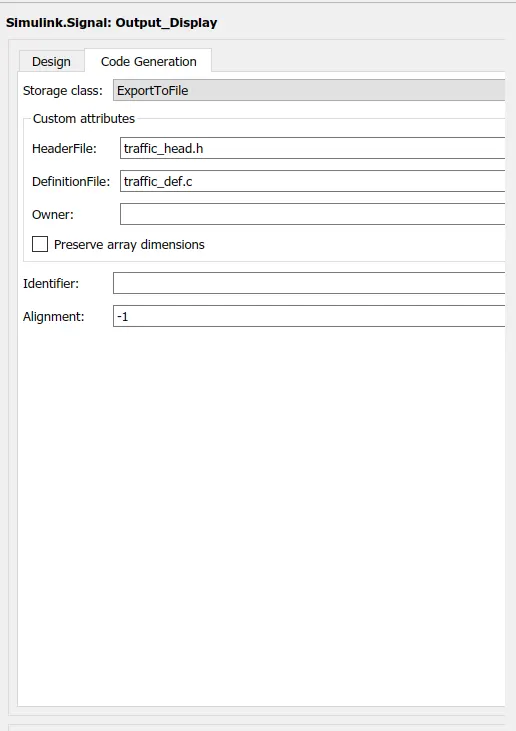
- In this, we have chose the Storage class for Input signals as ImportedExtern; Storage class for Output signal as Export to File; Storage class for local signals as localizable; Storage class for calibration signals as ConstVolatile.
- Sample time for all signals are taken as 0.01 sec as per given condition.
- While declaring output signal and constant values, we have given header file name as 'traffic_head.h' and definition file name as 'traffic_def.c'. The same is as under;
Requirement Tagging of Simulink Model:-
- The requirements ‘Requirement-1’ and ‘Requirement-2’ as provided in the Requirements Word document are tagged to their corresponding subsystem in the Simulink Model.
Steps for tagging a requirement in Simulink model :-
- First, we have highlight/ select the requirement statement in the Word document file. This word document file needs to be same MATLAB path.
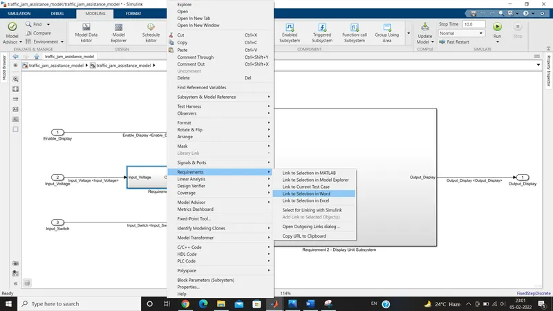
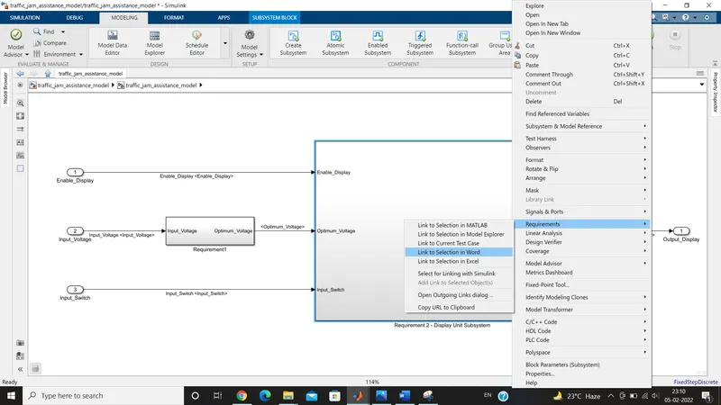
- Then, we have to go in Simulink Model and right click on particular subsystem, we need to tag. After right clicking, we have to select 'Requirements' and then click on 'link to Selection in word'. Then, the particular subsytem will get tagged for the highlighted text on word documents file.
- After doing sucessful tagging, MATLAB traceability file is generated in the same MATLAB path.
We have considered above steps while tagging the Requirement1 and Requirement2 and the same are as under;
Tagging for Requirement1 :-
Tagging for Requirement2 :-
Steps for Checking MAB Guidelines in Model Advisor :-
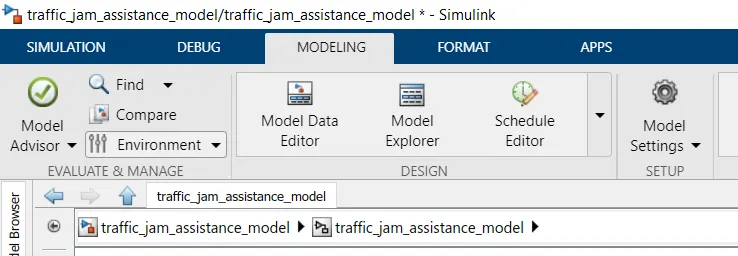
Step 1:-
We have to go into 'Modelling option' and then select 'Model Advisor'
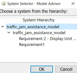
Step 2:-
We have to choose the system for checking Mathworks Automotive Advisory Board (MAB or MAAB) guidelines. In this case, we are checking full system check as under as per MAB guidelines;
Step 3 :-
Therafter, below screen appears. In this, we have to select as per Modelling standards for MAB guidelines.
Then, we have to click on 'Run Selected Check' option as under;
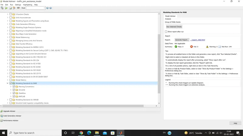
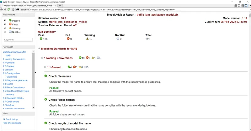
After running the model as per MAB Guidelines, we observed that it is sucessfully passed with value of 125 and total 19 nos. of warnings. However, there is no fail condition. Hence, we can conclude that above model is technically/logically correct.
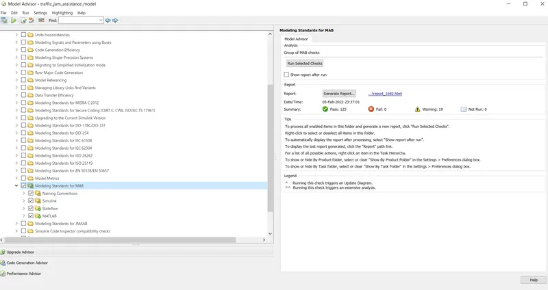
After successful running of model as per MAB guidelines, we observed that guideline report is generated in the same Matlab folder path. (The same is attached)
The screenshot for Model Advisor Report as per MAB guidelines/rules are as under;
Steps for Generation of Code from model:-
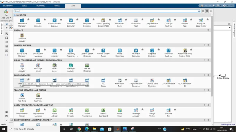
Step 1 :-
Go to Apps section and under Code Generation section, select Embedded Coder option.
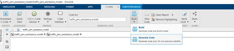
Step 2 :-
Then, under Embedded C Code section, Click on Generate Code option as under;
Step 3 :-
In the generation of code, there is one main c file, 4 nos. of model files, 2 data files, 1 one utility file is generated as under;
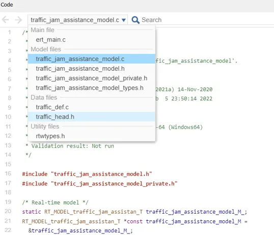
The code file generated is as under;
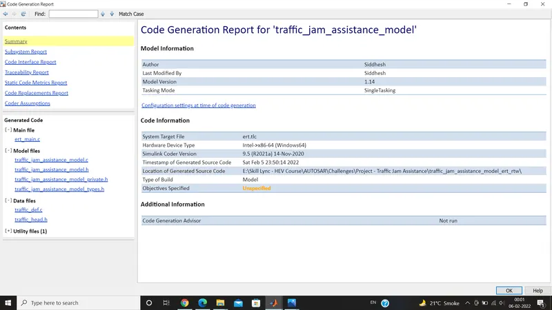
Code Generation Report :-
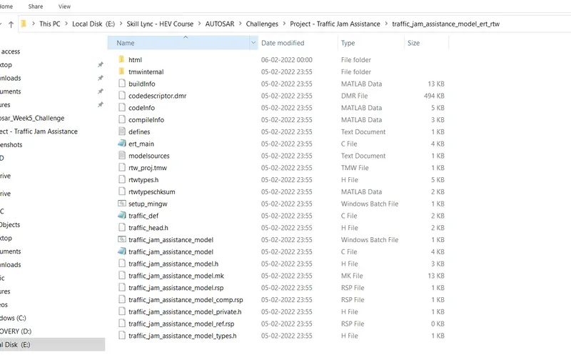
After sucessful completion of Code generation, traffic_jam_assistance_model_ert_rtw folder is created in the Matlab path as under;

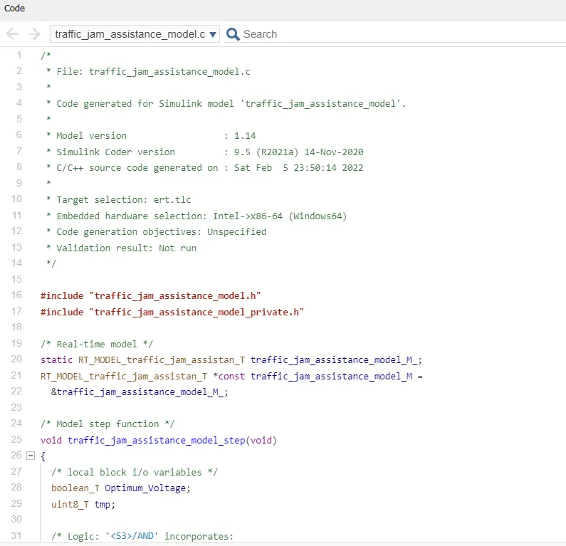
The generated full C Code for traffic_jam_assistance_model.c is as under;
/*
 * File: traffic_jam_assistance_model.c
 *
 * Code generated for Simulink model 'traffic_jam_assistance_model'.
 *
 * Model version                  : 1.14
 * Simulink Coder version         : 9.5 (R2021a) 14-Nov-2020
 * C/C++ source code generated on : Sat Feb  5 23:50:14 2022
 *
 * Target selection: ert.tlc
 * Embedded hardware selection: Intel->x86-64 (Windows64)
 * Code generation objectives: Unspecified
 * Validation result: Not run
 */

#include "traffic_jam_assistance_model.h"
#include "traffic_jam_assistance_model_private.h"

/* Real-time model */
static RT_MODEL_traffic_jam_assistan_T traffic_jam_assistance_model_M_;
RT_MODEL_traffic_jam_assistan_T *const traffic_jam_assistance_model_M =
  &traffic_jam_assistance_model_M_;

/* Model step function */
void traffic_jam_assistance_model_step(void)
{
  /* local block i/o variables */
  boolean_T Optimum_Voltage;
  uint8_T tmp;

  /* Logic: '<S3>/AND' incorporates:
   *  Constant: '<S3>/Constant'
   *  Constant: '<S3>/Constant2'
   *  Inport: '<Root>/Input_Voltage'
   *  RelationalOperator: '<S3>/GreaterThanOrEqual'
   *  RelationalOperator: '<S3>/GreaterThanOrEqual1'
   */
  Optimum_Voltage = ((Input_Voltage >= VOLTAGE_MINIMUM_RANGE) && (Input_Voltage <=
    VOLTAGE_MAXIMUM_RANGE));

  /* Switch: '<S2>/Switch' incorporates:
   *  Constant: '<S2>/Constant4'
   *  Constant: '<S2>/Constant5'
   *  Inport: '<Root>/Input_Switch'
   *  Logic: '<S2>/AND'
   *  Logic: '<S2>/NOT'
   *  RelationalOperator: '<S2>/Equal'
   */
  if (Optimum_Voltage && (!Input_Switch) && (INTERRUPT_1 == INTERRUPT_2)) {
    /* Saturate: '<S2>/Saturation' incorporates:
     *  Inport: '<Root>/Enable_Display'
     */
    if (Enable_Display < 7) {
      tmp = Enable_Display;
    } else {
      tmp = 7U;
    }

    /* End of Saturate: '<S2>/Saturation' */

    /* MultiPortSwitch: '<S2>/Multiport Switch' */
    switch (tmp) {
     case 1:
      /* Switch: '<S2>/Switch' incorporates:
       *  Constant: '<S2>/Constant'
       */
      Output_Display = ON_MODE;
      break;

     case 2:
      /* Switch: '<S2>/Switch' incorporates:
       *  Constant: '<S2>/Constant'
       */
      Output_Display = ON_MODE;
      break;

     case 3:
      /* Switch: '<S2>/Switch' incorporates:
       *  Constant: '<S2>/Constant1'
       */
      Output_Display = OFF_MODE;
      break;

     case 4:
      /* Switch: '<S2>/Switch' incorporates:
       *  Constant: '<S2>/Constant1'
       */
      Output_Display = OFF_MODE;
      break;

     default:
      /* Switch: '<S2>/Switch' incorporates:
       *  Constant: '<S2>/Constant2'
       */
      Output_Display = STANDBY_MODE;
      break;
    }

    /* End of MultiPortSwitch: '<S2>/Multiport Switch' */
  } else {
    /* Switch: '<S2>/Switch' incorporates:
     *  Constant: '<S2>/Constant3'
     */
    Output_Display = NO_DISPLAY;
  }

  /* End of Switch: '<S2>/Switch' */
}

/* Model initialize function */
void traffic_jam_assistance_model_initialize(void)
{
  /* (no initialization code required) */
}

/* Model terminate function */
void traffic_jam_assistance_model_terminate(void)
{
  /* (no terminate code required) */
}

/*
 * File trailer for generated code.
 *
 * [EOF]
 */