Project 2
AIM:
To create a P1 Hybrid Model and understand its functionality.
OBJECTIVES:
- To quantify the improvement in fuel economy numbers for the hybrid vehicle (kmpl), compared to the conventional vehicle, on the urban cycle (UDDS) and highway cycle (HWFET).
- To analyze and understand the vehicle operating points in terms of engine and motor speed, torque, transmission speeds, pedal positions, gear, distance traveled, battery voltage, current, SoC etc.
INTRODUCTION:
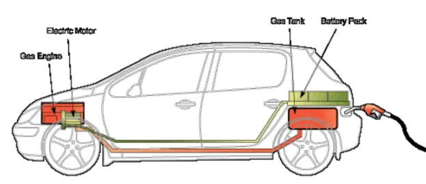
- A 'hybrid electric vehicle' is a vehicle which relies not only on batteries but also on an internal combustion engine which drives a generator to provide the electricity and may also drive a wheel.
- A 'gasoline-electric hybrid vehicle' is an automobile which relies not only on gasoline but also on electric power source.
- In HEV, the battery alone provides power for low-speed driving conditions.
- During long highways or hill climbing, the gasoline engine drives the vehicle solely.
- Hybrid electric vehicles comprise of an electric motor, inverter, battery as electric drive and an internal combustion engine with transmission connected as gasoline based drive.
- It is to achieve better fuel economy and reduce toxic emissions.
- It has great advantages over the previously used gasoline engine that is driven solely from gasoline.
- This hybrid combination makes the vehicle dynamic in nature and provides its owner a better fuel economy and lesser environmental impact over conventional automobiles.
- Hybrid electric vehicles are powered by an internal combustion engine and an electric motor, which uses energy stored in batteries.
- A hybrid electric vehicle cannot be plugged in to charge the battery. Instead, the battery is charged through regenerative braking and by the internal combustion engine.
- The extra power provided by the electric motor can potentially allow for a smaller engine.
- The battery can also power auxiliary loads and reduce engine idling when stopped.
- Together, these features result in better fuel economy without sacrificing performance.
BASIC DESIGN OF HEV:
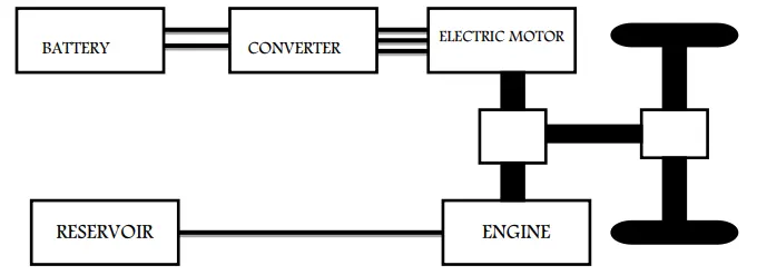
- The basic design consists of a dc power source battery.
- The battery is connected to inverter that is fed to a BLDC motor that works on AC.
- The motor is attached to the front wheel of the two wheeler vehicle.
- As the motor rotates the attached wheel rotates too, thus, leading to vehicle motion.
- At low speeds this mode of propulsion is used.
- The next phase consists of an IC engine that moves the piston continuously.
- This is connected to the transmission and thus, the vehicle moves.
ADVANTAGES OF HEV:
- HEVs have been vehicles of numerous advantages. Hybrids do indeed get superior gas mileage.
- They use less gasoline, and therefore emit less greenhouse gas.
- Thus the problem of environmental pollution can be avoided to certain extent.
- Apart from that they use less gasoline in comparison to the other vehicles of same power that run only on gasoline.
- Thus this reduces the extreme dependence on gasoline which is a non-renewable source of energy.
- This encourages the method of sustainable development that has been the topic of concern in the modern society.
- Moreover, HEVs mode of operation are maximum efficient to the conditions, i.e, at low speed and high traffic areas where gasoline engine is least efficient with a lot of energy wasted, HEV moves with power from battery.
- At up slopes where high power is required and battery is inefficient, gasoline power is used for vehicle motion.
- Thus the advantages of HEV make it superior than any other vehicle of today.
KEY COMPONENTS OF AN HYBRID ELECTRIC VEHICLE:
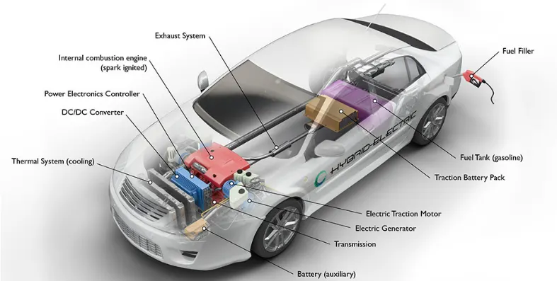
- Battery (auxiliary): In an electric drive vehicle, the low-voltage auxiliary battery provides electricity to start the car before the traction battery is engaged; it also powers vehicle accessories.
- DC/DC converter: This device converts higher-voltage DC power from the traction battery pack to the lower-voltage DC power needed to run vehicle accessories and recharge the auxiliary battery.
- Electric generator: Generates electricity from the rotating wheels while braking, transferring that energy back to the traction battery pack. Some vehicles use motor generators that perform both the drive and regeneration functions.
- Electric traction motor: Using power from the traction battery pack, this motor drives the vehicle's wheels. Some vehicles use motor generators that perform both the drive and regeneration functions.
- Exhaust system: The exhaust system channels the exhaust gases from the engine out through the tailpipe. A three-way catalyst is designed to reduce engine-out emissions within the exhaust system.
- Fuel filler: A nozzle from a fuel dispenser attaches to the receptacle on the vehicle to fill the tank.
- Fuel tank (gasoline): This tank stores gasoline on board the vehicle until it's needed by the engine.
- Internal combustion engine (spark-ignited): In this configuration, fuel is injected into either the intake manifold or the combustion chamber, where it is combined with air, and the air/fuel mixture is ignited by the spark from a spark plug.
- Power electronics controller: This unit manages the flow of electrical energy delivered by the traction battery, controlling the speed of the electric traction motor and the torque it produces.
- Thermal system (cooling): This system maintains a proper operating temperature range of the engine, electric motor, power electronics, and other components.
- Traction battery pack: Stores electricity for use by the electric traction motor.
- Transmission: The transmission transfers mechanical power from the engine and/or electric traction motor to drive the wheels.
P1 HYBRID VEHICLE MODEL:
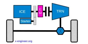
- The hybrid electric vehicle (HEV) P1 reference application represents a full HEV model with an internal combustion engine, transmission, battery, motor, and associated powertrain control algorithms.
-
The P1 architecture, with the electric machine connected directly to the crankshaft, is the solution adopted by Honda on their first generation Integrated Motor Assist (IMA) technology. The electric motor functions as a generator, during vehicle deceleration, as an engine starter, and as a motor (to assist the engine) during vehicle accelerations.
-
One of the biggest advantage of this solution is that the electric motor can provide higher torque than the BiSG, since there is no belt limitation (due to slip). However, since there is no speed / torque ratio between the electric machine and crankshaft, the torque requirements on the electric motor can be quite demanding.
-
Two examples of P1 MHEV architectures are:
-
Honda Insight Hybrid 2009 (with Integrated Motor Assist technology)
-
Mercedes Benz S400 Bluehybrid 2010
-
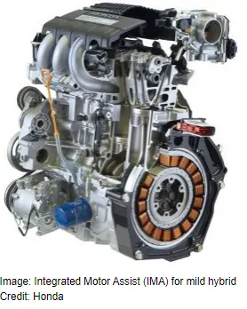
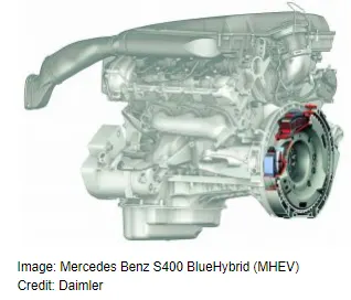
-
The primary advantage of a P1 mild hybrid architecture, compared with P0, is the removal of the belt drive. This means that the efficiency increases a bit (no more belt losses) and the electric machine torque can be higher in terms of amplitude and response (no more belt slip).
-
The functions (modes) performed by this mild hybrid topology are similar with those of a BiSG (P0), but, overall, P1 configurations have two big disadvantages: higher cost and higher impact on the the existing vehicle architecture. Therefore, vehicle manufacturers and system suppliers are not investing in the further development of crankshaft-mounted integrated starter generator solution for MHEV applications.
OVERVIEW OF THE MODEL:
- The project discloses a P1 hybrid system consisting of an Electric and Internal Combustion(IC) based power drives.
- The wheels of the car is being propelled by battery and the internal combustion engine and a BLDC motor based electric power drive used for hybrid powering of the vehicle.
- The controller is designed to implement the switching between IC Engine and Electric motor depending on the power requirement and load conditions.
- for switching gears and throttle for Electric motor and Engine we will be using a supervisory controller.
DESIGN AND SPECIFICATION:
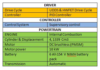
The following table shows the Specification and Design of the Electric Car modelled in MATLAB.
MATLAB MODEL:
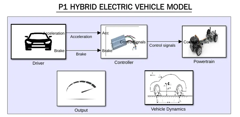
- This is a model representing the Hybrid Electric Car, where we have all the block performing individual operations.
- we have arranged the blocks as per their functions in a subsystem fashion.
- the input is delivered from the Driver where we will be using drive cycles, and producing output as Acceleration and Braking.
- with Acceleration and braking the output is fed as input to the controller, where the controller uses Supervisory control stratergy in regulating the control signal.
- the controller is connected to the powertrain system.
- the Distance and other parameters in the Objectives will be calculated in the Vehicle dynamics system and output will be displayed in the output block.
- now, lets discuss each and every systems briefly.
MATLAB CODE:
%%%%%%%%%%%%%%%%%%%%%%%%%%%%%%%%%%%%%%%%%%%%%%%%%%%%%%%%%%%%%%%%%%%%%
%% Skill-Lync -> Hybrid Drives Development
% Proj ect 1 - Conventional Vehicle Model
% By - Ullekh Gambhira

% Description:

%% Initialization File
% Initialization file for loading the variables for the Conventional vehicle simulation model

%% Vehicle Parameters
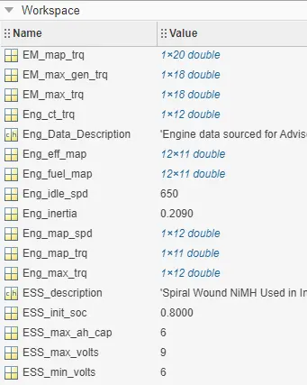
M = 1500;       % Vehicle weight [kg]
Cr = 0.015;     % Rolling resistance coefficient
Rw = 0.35;      % Rolling radius [m]
Cd = 0.33;      % Drag coefficient
Af = 2;         % Frontal area [m2]
rhoa = 1.225;   % Air density [kg/m3]
Vwind = 0;      % Wind velocity [kmph]
g = 9.81;       % Gravitational acceleration [m/s2]
theta = 0;      % Slope [deg]
myu_road_tire = 1; % Coefficient of friction between tire - road interface

Tm=150; % Motor Torque in Nm
efft=0.8; % Transmission efficiency
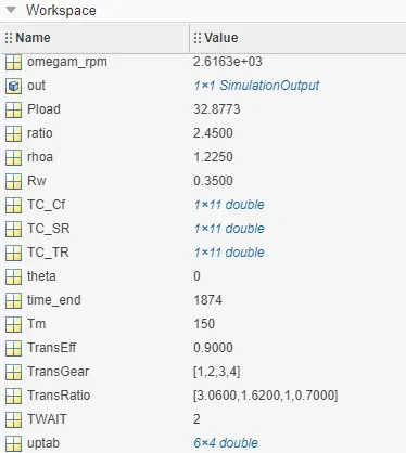
ratio=2.45; % Total ration

%%% Vehicle top speed
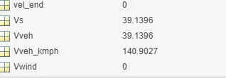
Vveh=sqrt((efft*ratio/Rw*Tm-Cr*M*g)*2/rhoa/Af/Cd);  %Vehicle velocity in m/s
Vveh_kmph=Vveh*18/5; % Vehicle velocity in kmph

%%% power for top speed
Fload=1/2*rhoa*Cd*Af*(Vveh+Vwind)^2+Cr*M*g*cosd(theta)+ M*g*sind(theta); % Road laod N
Pload=Fload*Vveh/1000; % Road load power kW
Vs=Vveh+Vwind;
% Powertrain Speed
omegam=ratio*Vveh/Rw; % Motor speed rad/s
omegam_rpm=omegam*30/pi; % motor speed rpm


%% Powertrain Parameters
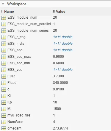
FDR = 3.73;                         % Final Drive Ratio / Diff Ratio
DiffEff = 0.99;                     % Differential efficiency (assumed independent of operating conditions)

NumGear = 4;                        % Number of gears in transmission
TransGear = [1:NumGear];            % Transmission Gears
TransRatio = [3.06, 1.62, 1, 0.7];  % Corresponding Transmission ratios
TransEff = 0.90;                    % Transmission efficiency (assumed independent of operating conditions)

TC_SR = [0, .5, .6, .7, .8, .87, .92, .94, .96, .97, 1];   % Torque Converter Speed Ratio (Matlab default) -> TurbSpd/PumpSpd
TC_TR = [2.232, 1.5462, 1.4058, 1.2746, 1.1528, 1.0732, 1.0192, 1, 1, 1, 1];   % Torque Converter Torque Ratio (Matlab default) -> TurbTrq/PumpTrq
TC_Cf = 1e-4 * [.72558, .66322, .63463, .59042, .51331, .4144, .29287, .22444, .12186, .04386, 0]; % Torque Converter Capacity Factor (Matlab default) -> PumpTrq/PumpSpd^2 [Nm/rpm^2]

load Engine_data_1_9L_Saturn_95kW.mat
load Trans_Shift_map.mat
load EM_Honda_Insight_10kW.mat
load ESS_NiMH6.mat


ESS_init_soc = 0.8;
ESS_soc_max = 0.9;
ESS_soc_min = 0.6;


%% Driver Parameters
Kp = 10;                    % P gain for driver PI model
Ki = 1;                     % I gain for driver PI model
Drive_Cycle_Select = 2;     % Drive cycle selection

% Drive cycle values in m/s

%if Drive_Cycle_Select == 1
    %load ('UDDS.mat');

%elseif Drive_Cycle_Select == 2
    %load HWFET.mat;

%elseif Drive_Cycle_Select == 3
    %load FTP.mat;

%elseif Drive_Cycle_Select == 4
    %load US06.mat;

%elseif Drive_Cycle_Select == 5
    %load NEDC.mat;

%elseif Drive_Cycle_Select == 6
    %load WLTP.mat;

%end

time_end = cyc_time(end);
vel_end = cyc_vel(end);

a=[1 2 3];
b=[3 6 9];
DRIVER SYSTEM:
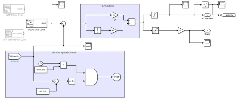
- the drive cycles produce the input speed.
- the drive cycles are customized with the singal builder block.
- this system compares the input speed and the vehicle speed using the sum block.
- for Drive cycle controll we are using a PID controller to tune the Drive cycle velocity.
- we have kp as 10 and ki as 1, and it tuned in a continuous time based.
- If the output is positive speed acceleration is given from the PI controller, and the negative output, deceleration is also given from the controlled.
- The output from the controller is controlled by the saturation blocks by given the upper and lower limits.
- inorder to send the braking in negative we are using a Negative to multiply with the help of gain block.
- for vehicle speed contoll we used the end time and end velocity operation to stop the simulation at the stipulated time.
Drive Cycle:
- Drive cycle is assumed as the driver's input of a vehicle.
- It is the Data representing the driving condition of a driver.
- these drive cycles will have high-speed, low-speed and braking conditions.
- these drive cycles will be generating signals from the singal builder block.
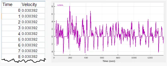
Urban Driving Drive Cycle (UDDS):
- The ECE is an urban driving cycle, also known as UDC.
- It was devised to represent city driving conditions, e.g. in Paris or Rome.
- It is characterized by low vehicle speed, low engine load, and low exhaust gas temperature.
Highway fuel economy test (HWFET):
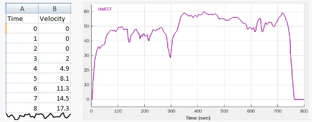
- The Highway Fuel Economy Test (HWFET or HFET) cycle is a chassis dynamometer driving schedule.
- it was developed by the US EPA for the determination of fuel economy of light duty vehicles [40 CFR 600, subpart B] .
- The HWFET is used to determine the highway fuel economy rating, while the city rating is based on the FTP-75 test.
CONTROLLER:
- The control system of Evolution is primarily responsible for coordination of the electric motor and internal combustion engine, maintaining a proper state-of-charge in the hybrid battery pack, and protecting the battery pack.
- Coordination of the engine and motor depends upon driver intent as communicated by the accelerator and brake pedals.
- Proper state of charge is maintained by employing either regenerative braking or by using the motor as a generator taking power from the engine.
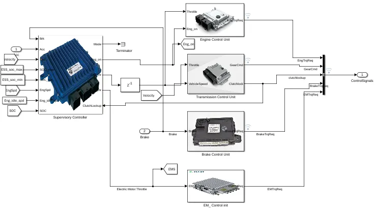
- the output from the driver as acceleration and braking is the input for the controller.
- in this system we have a supervisory controller, which uses a state flow logic to determine the Operating mode of the vehicle, it produces the Engine throttle, Electric Motor (EM) throttle and the engine on/off condition.
- the Eng_on condtion from the supervisory controller is given to the Engine Control unit, where the Engine control unit produces the required engine Torque.
- Transmission control unit, the throttle and speed is fed to the transmission, where the transmission controls the Gear level and the clutchlock up to monitor speed,
- Brake control unit, the brake output from the driver is supplied as input to the brake control unit, where the Required Brake torque is produced.
- Electric Motor(EM) control unit, the output from the supervisory controller is supplied to the EMCU, where the Required Brake Torque is Produced.
- a bus creator is used to create controll signals to pass the communications to the Powertrain.
- now, lets discuss each subsystem in detail.
SUPERVISORY CONTROL:
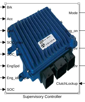
- A supervisory controller was developed to safely control the interactions between powertrain components.
- A power management control algorithm was developed to efficiently control the vehicle during charge sustaining operation.
- The task of the supervisory control systems is to assist the mode in the control of between Engine and Electric motor and in the control and monitoring of its torque.
- Such supervisory control systems are important parts of information system infrastructure of a Powertrain.
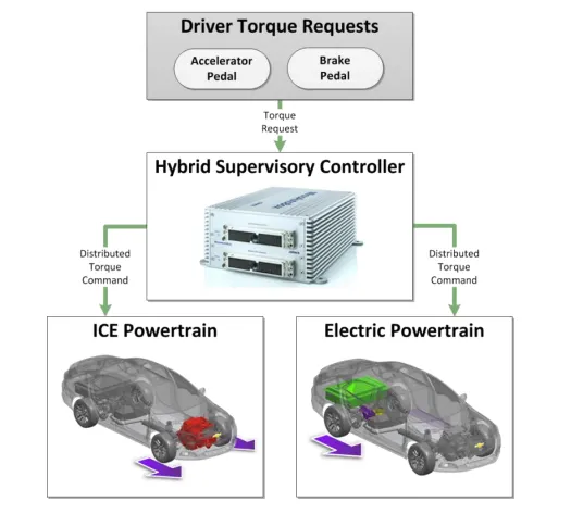
- The majority of the controls work throughout the years has been focused on developing programs that allow the vehicle’s Hybrid Supervisory Controller (HSC) to
interface with and control the different systems on the vehicle. - The primary purpose of the HSC is to receive inputs from the driver and intelligently determine how to distribute those requests to each powertrain system in a manner that is not only efficient, but also safe and acceptable to the average consumer.
- torque requests from the driver is distributed down to each of the powertrain systems.
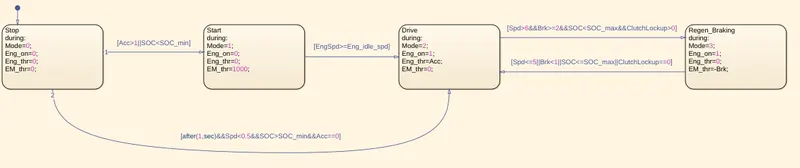
- the supervisory controller is designed in a State flow logic.
- we have 4 modes here i.e. stop, start, drive, Regenerative Braking.
- the mode 0 is the stop condition, in this condtion the Engine is Off, and there is no throttle for Eng or EM.
- when the Acceleration is less than 1 or SoC is less than the minimum Soc the logic hits the mode 1.
- the mode 1 si the start condition, since we have lower level acceleration EM drive mode hits the gas and revs for a throtlle of 1000.
- when the Eng speed is lesser than or Equal to the Engine idle speed, the mode changes to drive.
- in mode 2 we have the propulsion through engine, where the acceleration is equal to the Engine Throttle.
- when the speed is less than 6 and brake is lesser than or equal to 2 and SoC is less than SoC maximum and Clutchlockup is greater than 0, the control flows to the Regenerative Braking.
- but if spd is less than or equal to 5 and braking less than1 or SoC is less than or equal to the SoC max, and Clutchlockup is equal to 0, the controls flows back to the mode 2, Engine drive.
- if spped is less than 0.5 and Soc is greater than Soc_minimum and Acc is equal to 0, that is no acceleration then the control returns to the stop conditions.
ENGINE CONTROL UNIT:
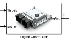
-
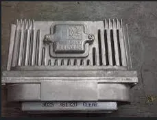
An engine control unit (ECU), also commonly called an engine control module (ECM), is a type of electronic control unit that controls a series of actuators on an internal combustion engine to ensure optimal engine performance.
-
The engine control unit (ECU) is the central controller and heart of the engine management system.
-
It controls the fuel supply, air management, fuel injection and ignition.
-
Due to the scalability of its performance, the control unit is also able to control the exhaust system as well as to integrate transmission and vehicle functions.
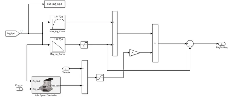
- The engine control unit manages all requirements for the engine, prioritizes and then implements them.
- we have inputs as Enigne on adn Eng Throttlle from the Supervisory controller.
- Torque serves as the key criterion for implementing all requirements.
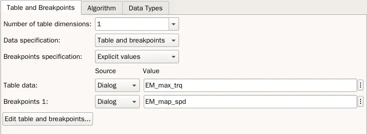
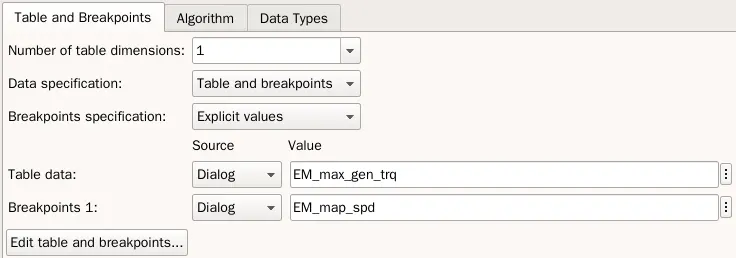
- It does this by reading values from the data using multidimensional performance maps (called lookup tables), and adjusting the engine actuators.
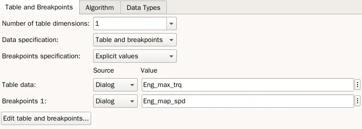
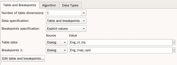
- these are the values from the workspace fed to the look up tables.
Idle Speed Controller:
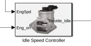
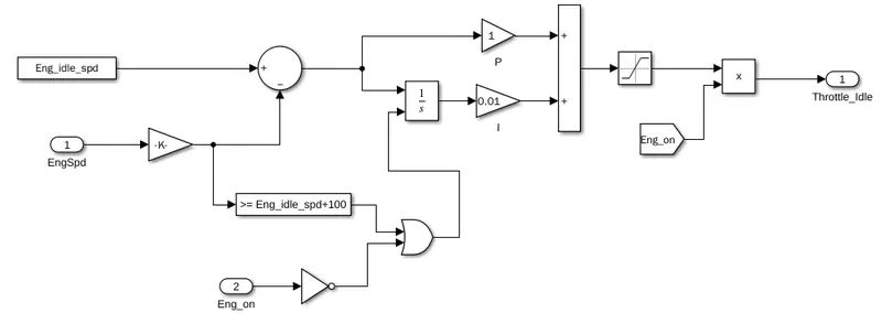
- An Idle Speed Control Valve is a device which controls the idle speed to the target speed and stabilizes the engine speed when the engine is stated.
- The idle speed control mode is used to prevent engine stall during idle.
- The goal is to allow the engine to idle at as low an RPM as possible yet keep the engine from running rough and stalling
- we have the input as Engine speed and Engine on, which is equal to the acceleration.
- The function of the idle speed contoller block is to maintain and control the engine idle speed.
- and also helps in maintaing the combustion ratio.
- for tuning the idle speed of the engine we are using the PID controller.
TRANSMISSION CONTROL UNIT:
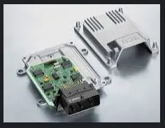
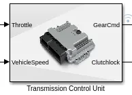
- The transmission control module is an electronic component of your transmission that's in charge of interpreting electrical signals from sensors in other parts of the vehicle.
- A transmission control unit (TCU), also known as a transmission control module (TCM), or a gearbox control unit (GCU), is a type of automotive ECU that is used to control electronic automatic transmissions.
- Similar systems are used in conjunction with various semi-automatic transmissions, purely for clutch automation and actuation.
- A TCU in a modern automatic transmission generally uses sensors from the vehicle, as well as data provided by the engine control unit (ECU), to calculate how and when to change gears in the vehicle for optimum performance, fuel economy and shift quality.
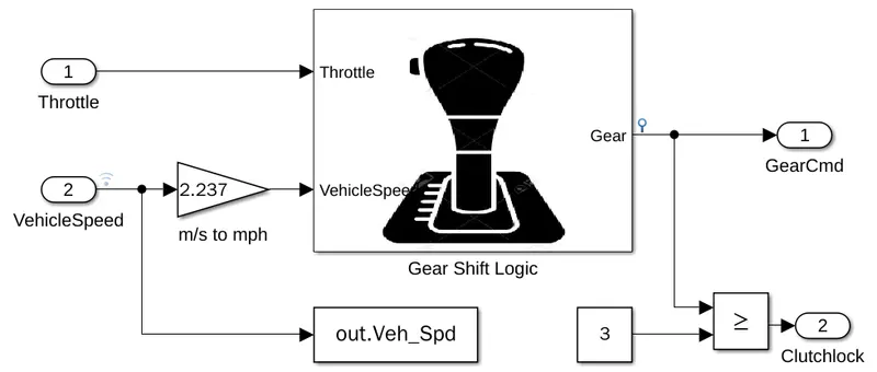
- The gearshift is used to move a vehicle forward, in reverse, or remain in neutral.
- here the gear shift is defined by a set of rules and logic, which decides the gear selection.
- we have throttle and speed as input to the gearing.
- and we get output as the Gear selected and clutch lock.
- The purpose of the Clutch Lockup is to make the engine speed a direct drive into the transmission.
- we are locking the clutch at 3rd gear or greater.
- this improves the fuel economy of the vehicle when cruising at a steady speed.
Gear Shift Logic:
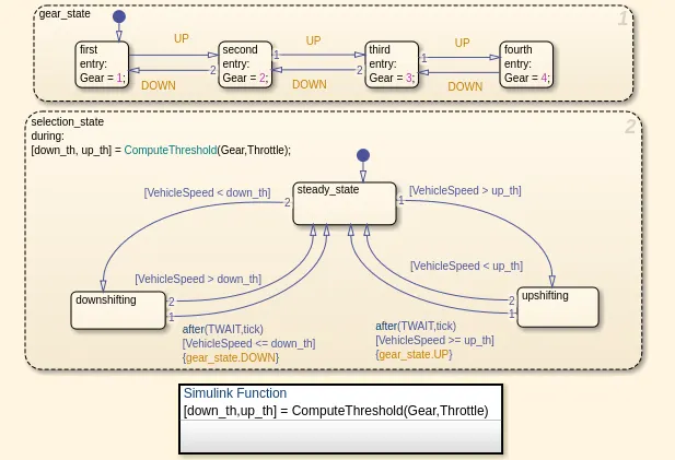
- The Stateflow chart models the shifting of gears based on throttle and speed of the vehicle.
- The down_threshold and up_threshold outputs represent minimum and maximum speed values that throttle and current gear are able to handle.
- The diagram contains two parallel states, gear_state and selection_state.
- gear_state consists of four exclusive states that indicate the gear status respectively, and the transition between them is guarded by events UP and DOWN.
- selection_state determines the direct broadcast of events UP and DOWN, according to the speed value and thresholds down_th and up_th.
- In addition, the broadcast is also restricted by some real-time constraints; for example, the transition that broadcasts event DOWN to state gear (denoted by {gear.DOWN}) is constrained by the temporal constraint after(TWAIT, tick) that checks if state downshifting has been active for at least TWAIT (a constant) period.
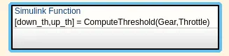
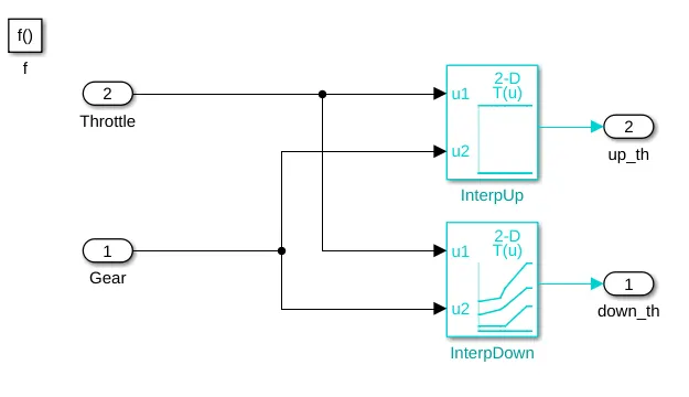
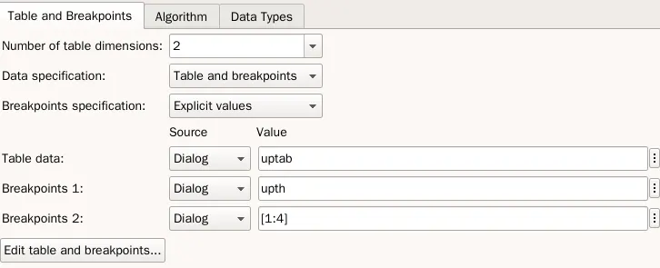
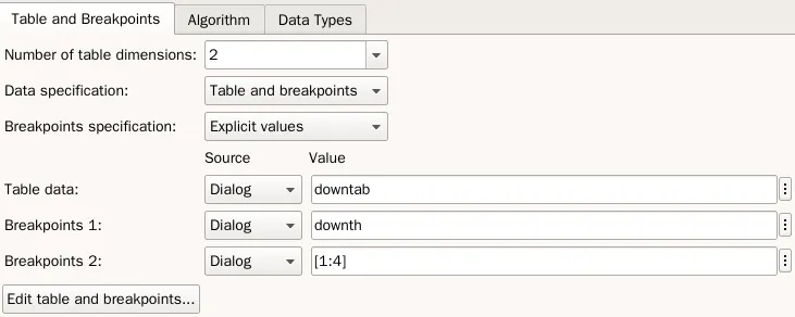
- The Simulink function calculate_thresholds calculates these two values using throttle and gear as inputs.
- If the actual speed is higher than up_threshold for longer than TWAIT, then the chart transitions to higher gear.
- Conversely, if the actual speed is lower than down_threshold for longer than TWAIT, then the chart transitions to a lower gear.
- At each time step, the chart calls the duration operator to find the amount of time for which speed is higher than up_threshold.
- If this time exceeds TWAIT then boolean variable up is set which in turn transitions chart from current gear to a higher gear.
- Conversely the chart transitions to a lower gear based on the value of down_threshold.
BRAKE CONTROL UNIT:
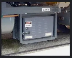
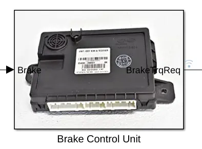
- The Brake Control Unit (computer) detects the inputs, and then checks the wheel speed sensors to determine vehicle speed, and to determine if a wheel lockup requires the ABS algorithm.
- A brake controller is an electronic device that regulates the electric trailer brakes. It allows the driver to activate and monitor trailer brake activity from the cab of the vehicle.
- Brake controllers help manage your stopping distance and control trailer sway by syncing up the two sets of brakes (tow vehicle and trailer) so that both activate when you need them.
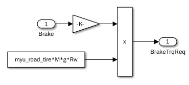
- we are converter the brake input from the driver with multiplying with rolling friction and weight and radius of the wheel.
- so with mathematical model we can obtain the Required Brake torque.
ELECTRIC MOTOR CONTROL UNIT:
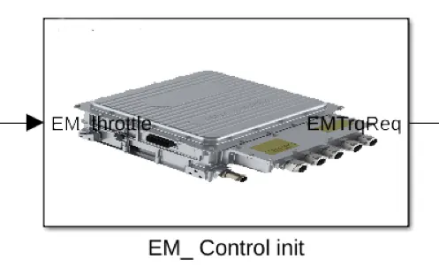
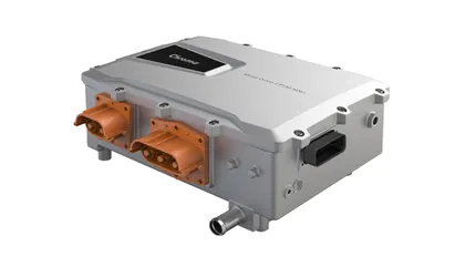
- Motor controllers are used with both direct current and alternating current motors.
- In the EMCU the Throttle is fed and required Em torque is taken as output.
- A controller includes means to connect the motor to the electrical power supply, and may also include overload protection for the motor, and over-current protection for the motor and wiring.
- The MCU converts battery pack DC power source to AC power supply to drive propulsion motor.
- During vehicle braking, it can regenerate DC power back to battery pack for charging.
- Efficient cooling system enables its high power density and performance.
- Protection includes against over current, over voltage and over temperature.
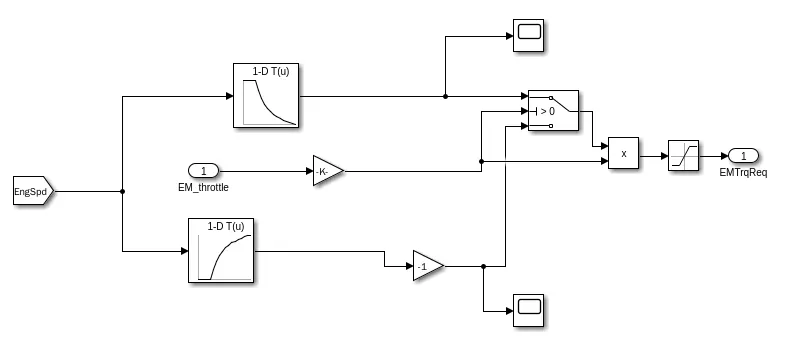
- EMCUs monitor the load on a motor and accordingly match motor torque to motor load.
- here the Motor torque is given in a datasheet.
- we are using lookup tables to fed the data in the model.
POWERTRAIN:
- Hybrid electric vehicles are powered by an internal combustion engine and an electric motor, which uses energy stored in batteries.
- A hybrid electric vehicle cannot be plugged in to charge the battery.
- Instead, the battery is charged through regenerative braking and by the internal combustion engine.
- Hybrid Vehicle Powertrain Systems combine conventional powertrain components, an internal combustion engine and transmission, with new electric components, electric motor, power electronics and high voltage energy storage, such as a battery.
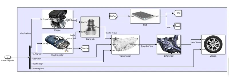
- the input is from the controller as control signals, we are using bus selector to spread the communication to all the systems.
- we have engine, Electric motor, Crank hub, Transmission, Differential, Battery and Wheels.
- lets discuss each system one by one.
ENGINE:
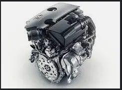
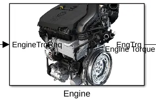
- An internal combustion engine (ICE or IC engine) is a heat engine in which the combustion of a fuel occurs with an oxidizer (usually air) in a combustion chamber that is an integral part of the working fluid flow circuit.
- In an internal combustion engine, the expansion of the high-temperature and high-pressure gases produced by combustion applies direct force to some component of the engine.
- The force is applied typically to pistons, turbine blades, a rotor, or a nozzle.
- This force moves the component over a distance, transforming chemical energy into useful kinetic energy and is used to propel, move or power whatever the engine is attached to.
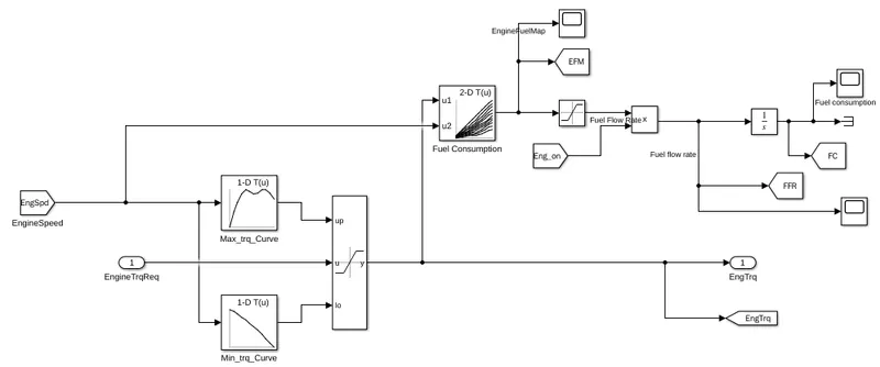
- the input for the engine here is the Required Engine Torque which was generated in the Engine control unit.
- It does this by reading values from the data using multidimensional performance maps (called lookup tables), and adjusting the engine actuators.
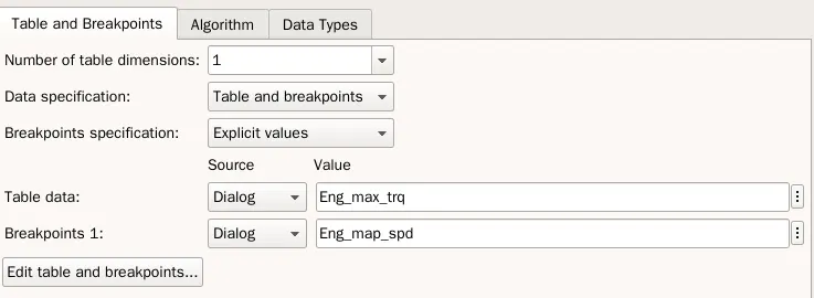
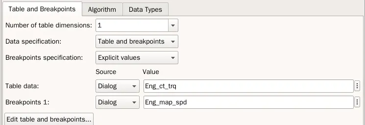
- the look up tables contain the values of Eng torque which is passed to saturation dynamic block.
- The Saturation Dynamic block produces an output signal that is the value of the input signal bounded to the saturation values from the input ports
upandlo. - we do have another 2D lookup table which reads the values of fuel comsumption.
- Using saturation block we are extracting the fuel flow rate and integrating the fuel flow rate we get the Fuel consumption.
- From the static dyanmic block we get the engine Torque.
ELECTRIC MOTOR:
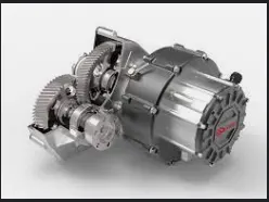
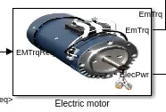
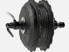
- the electric motor is able to draw power from the batteries as well as put energy into them.
- This means that when the electric motor is running, it can continually recharge the batteries inside the hybrid car.
- hybrid car's batteries are able to recover power when the brakes are applied.
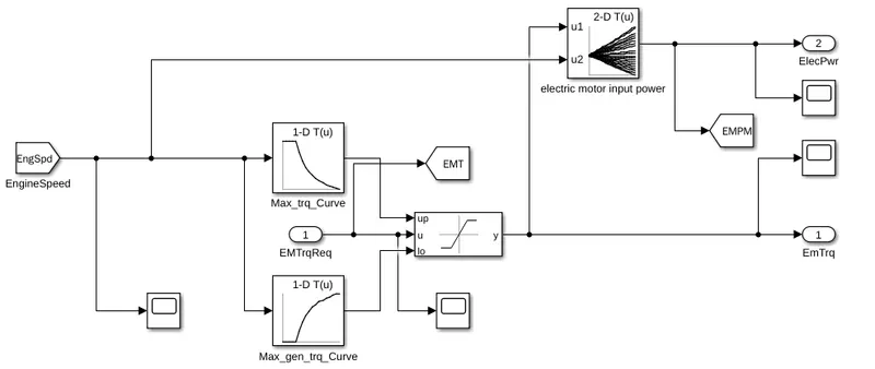
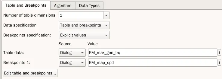
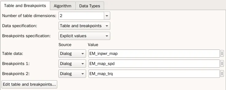
- from the above block daigram we can understand the Electric motor function, i.e. how Em Torque is caluculated.
- the Em torque from the EMCU is supplied as an input to the system.
- this system is similar to the Engine system.
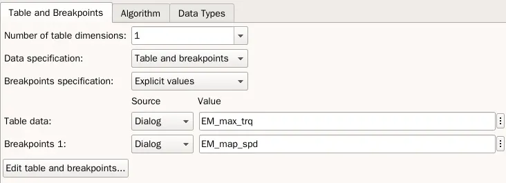
- Lookup tables are also used extensively to validate input speed by matching against a list of Torques to produce the expected Torque.
CRANK HUB:
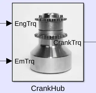
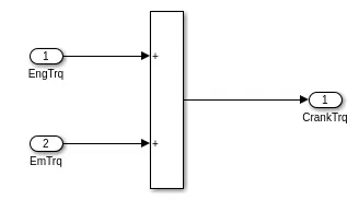
- the crank hub is a device which absorbs torque from both Engine and Electric Motor and distributes as a single torque to the Transmission.
TRANSMISSION:
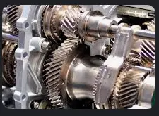
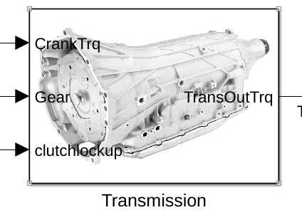
- The function of any transmission is transferring engine power to the driveshaft and rear wheels (or axle halfshafts and front wheels in a front-wheel-drive vehicle).
- Gears inside the transmission change the vehicle's drive-wheel speed and torque in relation to engine speed and torque.
- A car transmission is one of the most important components of a vehicle.
- It's what moves the power from the engine to the wheels.
- Whatever type of transmission it is, the answer to what does a transmission do is to enable the gear ratio between the drive wheels and engine to adjust as the car slows down and speeds up.
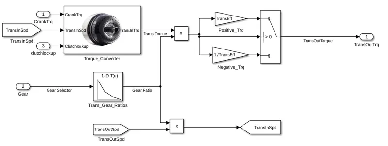
- the input for this block is the crank torque and clutch lock up.
- the torque converter absorbs the input torque and redistributes as Transmission input torque.
- we are using a lookup table to validate the gear selector by matching against a list of Gear ratios to produce the expected Torque.
- and with the help of switch block we are converting the multiple signals like positive torque and negative torque into a single input torque.
- this system gives us the transmission output torque.
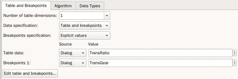
- we are using the trans_Gear_Ratio to get the Gear Ratio.
- the torque converter act as a coupling device.
Torque Converter:
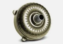
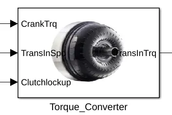
- torque converter is the same as the clutch of a vehicle with a manual transmission.
- However, unlike a manual transmission vehicle, it uses fluid to transmit power to the transmission preventing your engine from stalling and allowing the transmission to change.
- A torque converter is a type of fluid coupling that transfers rotating power from a prime mover, like an internal combustion engine, to a rotating driven load.
- In a vehicle with an automatic transmission, the torque converter connects the power source to the load.
- It is usually located between the engine's flexplate and the transmission.
- The equivalent location in a manual transmission would be the mechanical clutch.
- The main characteristic of a torque converter is its ability to increase torque when the output rotational speed is so low that it allows the fluid coming off the curved vanes of the turbine to be deflected off the stator while it is locked against its one-way clutch, thus providing the equivalent of a reduction gear.
- This is a feature beyond that of the simple fluid coupling, which can match rotational speed but does not multiply torque and thus reduces power.
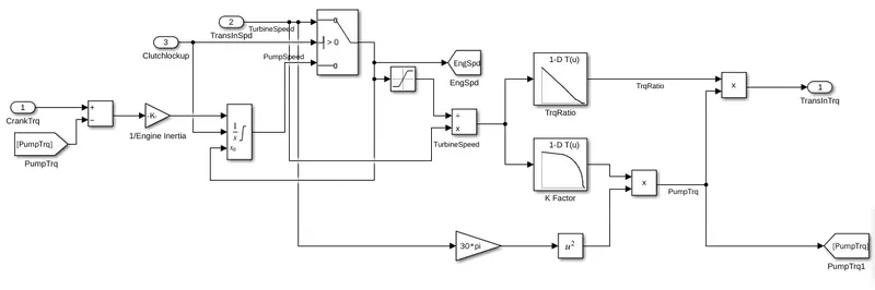
- the input is the crank torque, clutchlock up and transmission input speed.
- the pump torque is subtracted from crank torque for speed control.
- the integator block provides signal for the operation of the turbine inside the TC.
- a clutchlockup to improve cruising power transmission efficiency and reduce heat. The application of the clutch locks the turbine to the impeller, causing all power transmission to be mechanical, thus eliminating losses associated with fluid drive.
- we are using a lookup table to validate the turbine speed by matching against a list of Torque ration and k Factor to produce the expected Torque.
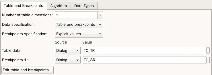
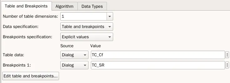
- the TC has a engine dynamics block, that has a integrator block to calcuate the speed.
- the pump torque act as the load of the engine the acceleration is divided by engine interia.
- tc have speed ratio, because turbine speed is different from pump speed.
- the torque ratio and k factor takes the input and has the array of table data and compares with break points.
DIFFERENTIAL UNIT:
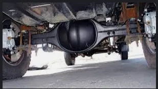
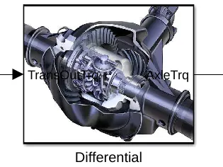
- Differentials are a variety of gearbox, almost always used in one of two ways. In automobile and other wheeled vehicles, the differential allows each of the driving wheels to rotate at different speeds, while supplying equal torque to each of them.
- The differential is designed to drive a pair of wheels while allowing them to rotate at different speeds. This function provides proportional RPMs between the left and right wheels. If the inside tire rotates 15 RPM less in a turn than going straight, then, the outside tire will rotate 15 RPM more than going straight.
- The differential is a system of gears that allows different drive wheels (the wheels to which power is delivered from the engine) on the same axle to rotate at different speeds, such as when the car is turning.
- if the car is making a turn to the right, the main ring gear may make 10 full rotations. During that time, the left wheel will make more rotations because it has farther to travel, and the right wheel will make fewer rotations as it has less distance to travel. The sun gears (which drive the axle half-shafts) will rotate at different speeds relative to the ring gear (one faster, one slower) by, say, 2 full turns each (4 full turns relative to each other), resulting in the left wheel making 12 rotations, and the right wheel making 8 rotations.
- The rotation of the ring gear is always the average of the rotations of the side sun gears. This is why if the driven roadwheels are lifted clear of the ground with the engine off, and the drive shaft is held (say, leaving the transmission in gear preventing the ring gear from turning inside the differential), manually rotating one driven roadwheel causes the opposite roadwheel to rotate in the opposite direction by the same amount.
- When the vehicle is traveling in a straight line there will be no differential movement of the planetary system of gears other than the minute movements necessary to compensate for slight differences in wheel diameter, undulations in the road which make for a longer or shorter wheel path, etc.
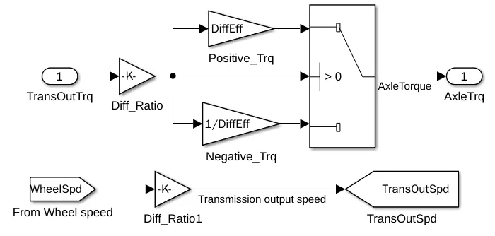
- the output torque from the transmission system is the input for the differential unit system.
- by multiplying it with differential ration we get multiple torque, with help of switch block we get the axle torque as output.
- the product of wheel speed and differential ratio is the transmission output speed.
- input as transmission output torque.
- the transouttrq is multiplied with the final differential ratio using gain block.
- we are using gain blocks to supress the negative torque.
- with the switching block, it has ports - command, condition, we can input the threshold value.
- wheel speed is multplied with Final drive ratio using the gain block, gives us the transmission output speed.
WHEEL:
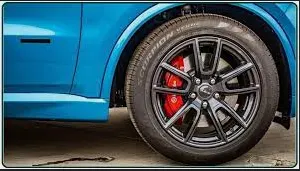
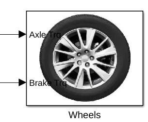
- A drive wheel is a wheel of a motor vehicle that transmits force, transforming torque into tractive force from the tires to the road, causing the vehicle to move.
- The powertrain delivers enough torque to the wheel to overcome stationary forces, resulting in the vehicle moving forwards or backwards.
- While dealing with the various forces that act on the vehicle, the tyres also help in absorbing and damping the shocks.
- The wheels of your vehicle change direction as you steer the steering wheel.
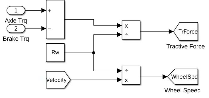
- with this block's help we can convert torque to force by dividing it by the wheel radius.
- the same velocity divided by radius of the wheel gives us the wheel speed.
- recives axle and brake torque, brakes retard axle torque.
- net wheel torque = tf-bf.
- net wheel torque/Rw= Tractive force.
- velocity/roll.raidus=wheelspeed.
- the axle torque and brake torque is connectected to the summation block.
- for declaring Rolling radius we are using a constant block, the Rw is defined in the workspace.
- with the help of divide block we are diving it with Rw.
- the tractive force is given as output.
- we already have velotiy, using the divide block, and dividing velocity with Rolling Radius we get the wheel speed.
ENERGY STORAGE SYSTEM:
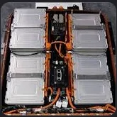
- Most plug-in hybrids and all-electric vehicles use lithium-ion batteries like these.
- Energy storage systems, usually batteries, are essential for hybrid electric vehicles (HEVs), plug-in hybrid electric vehicles (PHEVs), and all-electric vehicles (EVs).
- An electric-vehicle battery (EVB, also known as a traction battery) is a battery used to power the electric motors of a battery electric vehicle (BEV) or hybrid electric vehicle (HEV).
- These batteries are usually rechargeable (secondary) batteries, and are typically lithium-ion batteries.
- A battery is a device that stores chemical energy and converts it to electrical energy.
- The chemical reactions in a battery involve the flow of electrons from one material (electrode) to another, through an external circuit.
- The flow of electrons provides an electric current that can be used to do work.
- The nickel-metal hydride batteries found in hybrid vehicles are basically "zero-landfill" products.
- Whatever can't be recycled is consumed in the recycling process, leaving no trash behind. The primary metals recovered are nickel, copper and iron.
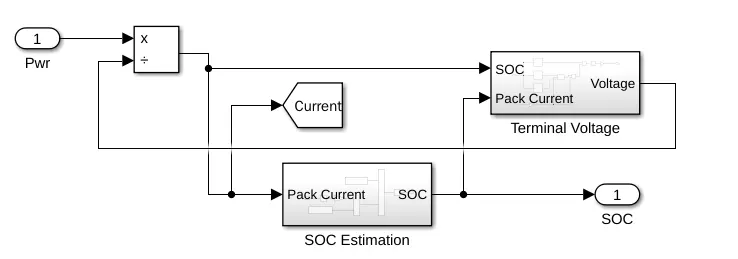
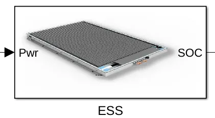
- The Energy storage system has the power has input divided by voltage gives us current.
- the current is given to SoC estimation block.
- and the SOC and current is supplied to the Terminal voltage.
- and for following a closed loop the voltage is again supplied to the power.
SoC Esitmation:
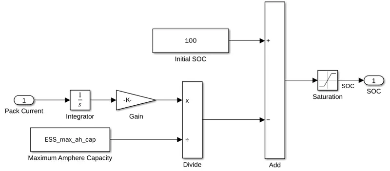
- the pack current is integrated and divided with the maximum amphere capacity.
- and then subtracted from the initial SoC to esitmate the SoC.
Terminal Voltage:
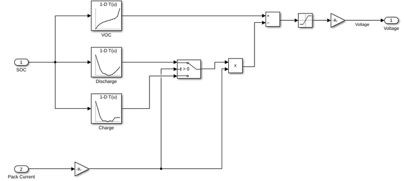
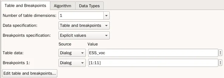
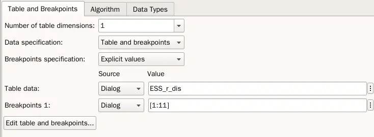
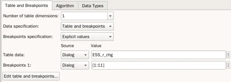
- the Soc from the Soc estimation block is supplied as input to the Voltage across the currect, discharge and charge look up tables.
- and then mulptipled with pack current and subtracted with Voltage across current gives us the Terminal voltage.
VEHICLE DYNAMICS:
Vehicle Dynamics systems prevent vehicles from spinning or slipping when cornering sharply by controlling vehicle yaw moment, which is generated by braking forces. Thus, it is important to control braking forces depending on the driving conditions of the vehicle.
The vehicle dynamics is the motion of the vehicle generated by the steering action, through which the vehicle is capable of independent motion. This chapter explains the motion of the vehicle for a given steer input, and explains the mechanics of vehicle motion.
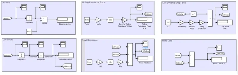
- In the Vehicle dynamics block we will be calculating the Distance travelled by the Vehicle, Rolling Resistance Force, Drag Force, Road Resistance, Road Load and Estimated Velocity.
Distance:
- we know that the Distance is obatined by Intergating Velocity.
- the solutions will be displayed in the display block.
- for meter to kilo meter conversion we are dividing Velocity in m with 1000 to get Km.
Rolling Resistance Force:
- Rolling resistance takes on an even greater importance for electric cars.
- Lower rolling resistance means increased electric range and higher efficiency, while also contributing to your car's overall sustainability.
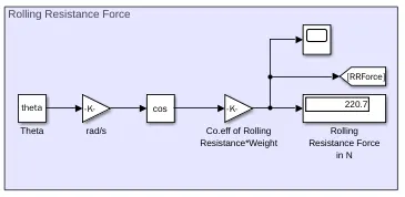
- using the formula `Cr*M*g*cos theta`, we can Calculate the Rolling resistance force
- where,
- Cr is the Rolling resistance Coefficient.
- M is the Weight of the Vehicle.
- Theta is the Gradient Angle.
- we will be using the formula with respective blocks.
Aero Dynamic Drag Force:
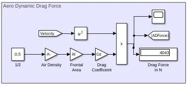
- the aerodynamic drag force parameters which represents the air resistance on an electric vehicle motion performance.
- these parameters are the aerodynamic drag coefficient, the equivalent frontal area of the vehicle, and the head-wind velocity.
- using the formula `1/2 rho*a*v^2 * d`, we can calculate the Drag Force.
- where,
- ρ is the density of air in kg/m^3.
- a is the frontal area.
- V is the velocity
- d is the drag coefficient.
- we will be using the formula with respective blocks.
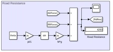
Road Resistance:
- Road resistance is an important pavement safety evaluation parameter.
- poor road resistance can lead to skidding accidents and inadequate braking distance during emergency braking.
- we are using the formula of Rolling resistance + Aerodynamic Drag +`Cr*M*g*sin theta` .
- we will be using the formula with respective blocks.
Road Load:
- Road load is a method for measuring precise vehicle response.
- It takes into account all types of essential vehicle and driving parameters, such as mass, inertia, air and rolling resistance, road characteristics, engine loads and vehicle speed.
Estimated Velocity or Calculated Velocity:
- Velocity measures motion starting in one place and heading toward another place.
- The practical applications of velocity are endless, but one of the most common reasons to measure velocity is to determine how quickly you (or anything in motion) will arrive at a destination from a given location.
- here the velocity is achieved by integrating Road Load.
OUTPUT BLOCK:
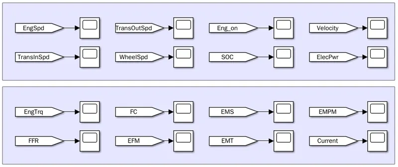
- the output block system, gives us the output which was asked in the objectives.
OUTPUT:
- Now lets run the model with driver as Urban dynamometer Driving Schedule (UDDS).
- and observe the outputs from the scopes.
- it is noticed that the output follows the Drive cycle given as input.
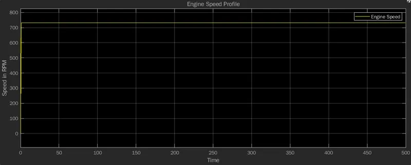
- from the Engine speed profile graph we can understand the Engine speed.
- we have speed in x axis and time in y axis.
- the engine speed follows the Drive cycle which is given as input.
- the engine speed is 720 RPM.
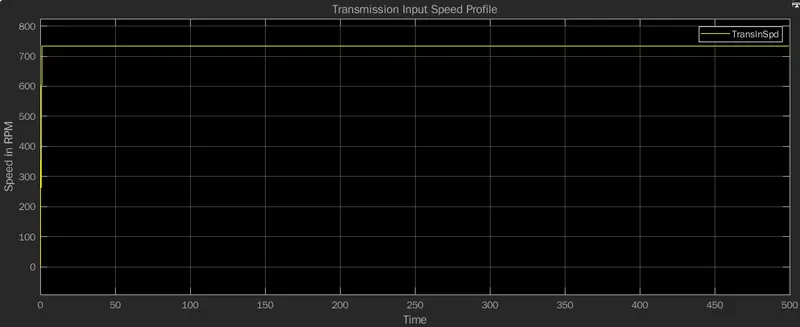
- from the Transmission input speed profile graph we can understand the Transmission input speed.
- it is noticeable that transmission speed is equal to the Engine speed.
- then transmission input speed is 720 RPM and maintian its course.
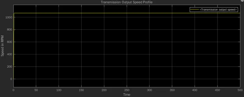
- from the Transmission output speed profile graph we can understand the Transmission output speed.
- the transmission output speed is 1300 RPM and maintians its course.
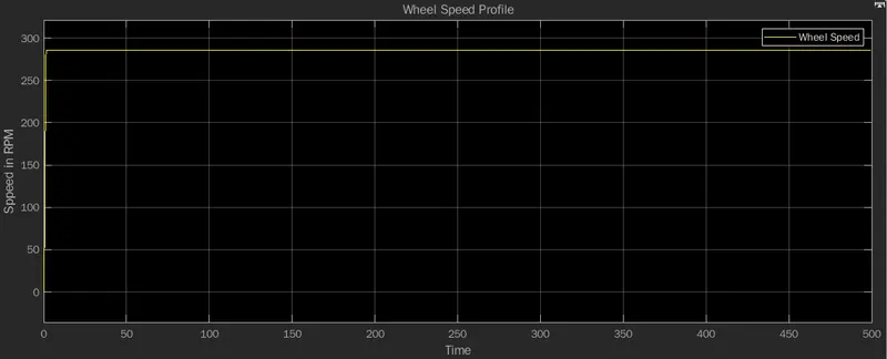
- from the Wheel speed profile graph we can understand the Wheel speed.
- and it is understood that the wheel speed is 280 RPM.
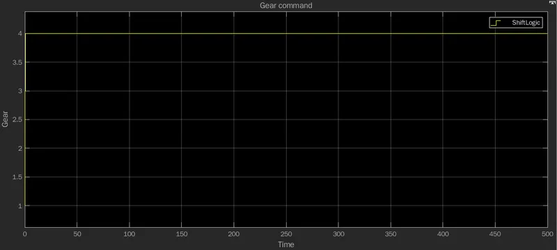
- as we can see the gear command from the TCU is 4.
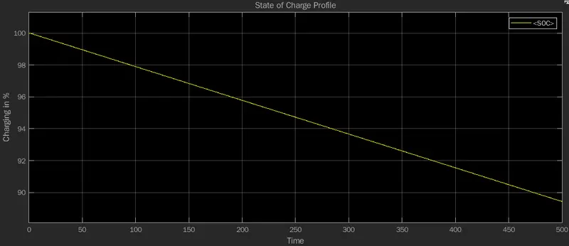
- The value of the SOC varies between 0% and 100%.
- If the SOC is 100%, then the cell is said to be fully charged, whereas a SOC of 0% indicates that the cell is completely discharged.
- so it is understood that driving in UDDS reduces 10% and has remaining 90% charge Capcity.
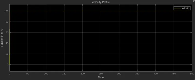
- from the velocity profile graph we can understand the velocity of the vehicle.
- as per the saturation output we can see the velocity is 100 m/s.
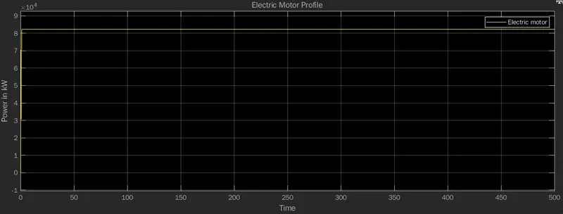
- Power is the rate with respect to time at which work is done
- the power of Electric motor is 80kW.
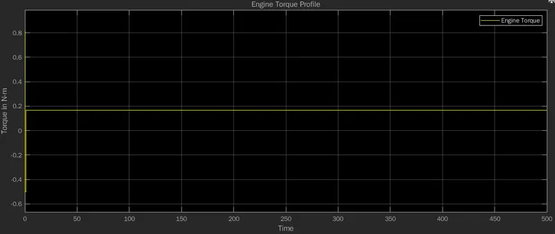
- from the engine torque profile we can understand the engine torque.
- the engine torque is 0.19 kN-m.
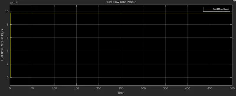
- from the fuel flow rate profile we can understand the fuel flow rate.
- we have fuel flow rate in kg/s in x axis and time in y axis.
- so the fuel flow rate to the combustion is 9.5 kg/s.
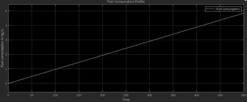
- from the fuel comsumption profile we can understand the Fuel consumption of the Engine.
- as we can see the recorded comsumption is 5 kg/s.
- and continous its course as time increases, consmuption increases.
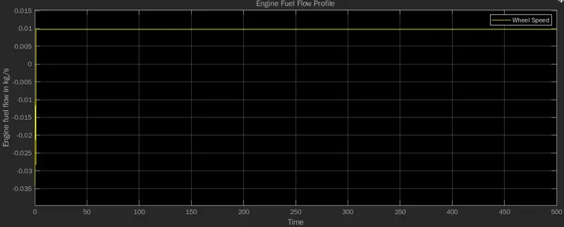
- the engine fuel flow map gives the flow as 0.01 kg/s.
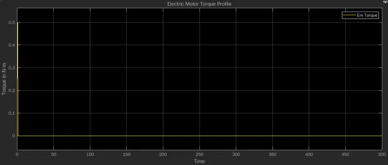
- since the vehicle is driving in the Engine mode, there is no torque from the Electric motor side.
- but initially produces 0.5 N-m torque for propulsion.
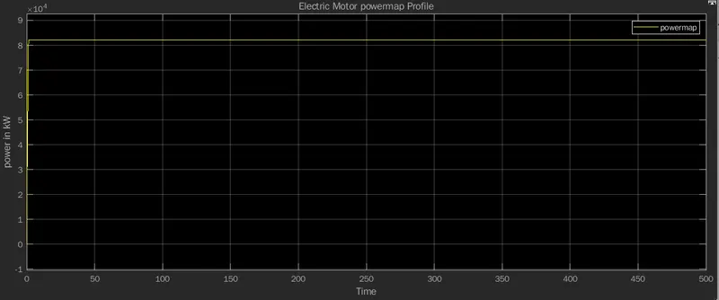
- the power produced as per the powermap is 80 kW.
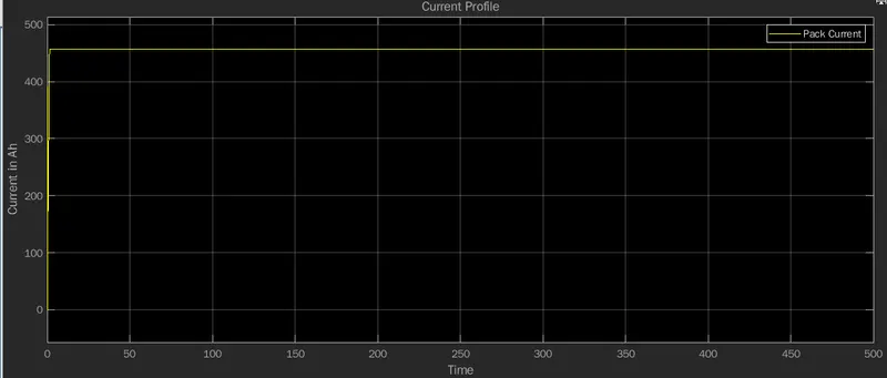
- from the current profile graph we can understand the current behavior.
- the pack current is from the Energy storage system.
- the current is 450 Ah.
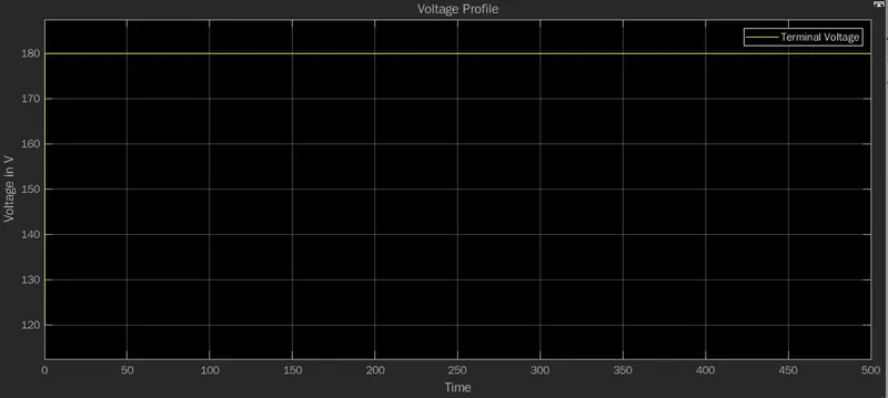
- from the voltage profile graph we can understand the voltage of the battery pack.
- the terminal voltage is 180 V.
Output from the Vehicle Dynamics system:
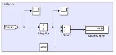
- the distance travelled by the UDDS drive cycle of the vehicle is 50 km.
- the rolling resistance force of the vehicle is 220.7 N.
- the Aerodynamic Drag force of the vehicle is 4.04 kN.
- the road Resistance of the vehicle is 4.26
CASE 2:
- now lets change the drive cycle to HWFET.
- and observe the outputs from the scopes.
- it is noticed that the output follows the Drive cycle given as input.
- it is understood that this drive cyles drives in Engine mode.
- so the outputs will be similar to the previous drive cycle results.
Output from Output Subsystem:
- from the Engine speed profile graph we can understand the Engine speed.
- we have speed in x axis and time in y axis.
- the engine speed follows the Drive cycle which is given as input.
- the engine speed is 720 RPM.
- from the Transmission input speed profile graph we can understand the Transmission input speed.
- it is noticeable that transmission speed is equal to the Engine speed.
- then transmission input speed is 720 RPM and maintian its course.
- from the Transmission output speed profile graph we can understand the Transmission output speed.
- the transmission output speed is 1300 RPM and maintians its course.
- from the Wheel speed profile graph we can understand the Wheel speed.
- and it is understood that the wheel speed is 280 RPM.
- as we can see the gear command from the TCU is 4.
- The value of the SOC varies between 0% and 100%.
- If the SOC is 100%, then the cell is said to be fully charged, whereas a SOC of 0% indicates that the cell is completely discharged.
- so it is understood that driving in UDDS reduces 10% and has remaining 90% charge Capcity.
- from the velocity profile graph we can understand the velocity of the vehicle.
- as per the saturation output we can see the velocity is 100 m/s.
- Power is the rate with respect to time at which work is done
- the power of Electric motor is 80kW.
- from the engine torque profile we can understand the engine torque.
- the engine torque is 0.19 kN-m.
- from the fuel flow rate profile we can understand the fuel flow rate.
- we have fuel flow rate in kg/s in x axis and time in y axis.
- so the fuel flow rate to the combustion is 9.5 kg/s.
- from the fuel comsumption profile we can understand the Fuel consumption of the Engine.
- as we can see the recorded comsumption is 5 kg/s.
- and continous its course as time increases, consmuption increases.
- the engine fuel flow map gives the flow as 0.01 kg/s.
- since the vehicle is driving in the Engine mode, there is no torque from the Electric motor side.
- but initially produces 0.5 N-m torque for propulsion.
- the power produced as per the powermap is 80 kW.
- from the current profile graph we can understand the current behavior.
- the pack current is from the Energy storage system.
- the current is 450 Ah.
- from the voltage profile graph we can understand the voltage of the battery pack.
- the terminal voltage is 180 V.
Output from the Vehicle Dynamics system:
- the distance travelled by the HWFET drive cycle of the vehicle is 50 km.
- the rolling resistance force of the vehicle is 220.7 N.
- the Aerodynamic Drag force of the vehicle is 4.04 kN.
- the road Resistance of the vehicle is 4.26
RESULT:
- thus the P1 Hybrid vehicle is been modelled successfully.
- the functionalites in different drive cycle evnornment is also studied.
- the given objectives are achieved.
HYBRID ELECTRIC VEHICLE POPULARITY IN INDIA:
- Hybrid vehicles are a better fit than battery-powered electric cars for India in the immediate future, given the nation’s shortcomings in EV infrastructure, according to the regional head of auto parts supplier Schaeffler
- “Hybrid vehicles will play an equally important role because they are able to address some of the immediate infrastructure challenges around e-mobility,” Dharmesh Arora, Schaeffler’s Asia Pacific chief executive officer, said in an interview with Bloomberg TV on Monday. “For electric mobility to become mainstream we could argue it will take some more years or longer than rest of the world.”
- Schaeffler’s outlook echoes the stance of India’s biggest carmaker Maruti Suzuki NSE 6.83% india Ltd. which is also glum about the uptale of Electric Vehicles and is focusing on hybrid models until charging infrastructure improves and EVs become more affordable for Indian buyers. Electric vehicles account for less than 1% of India’s annual car sales, compared to almost 10% in China.
- Schaeffler is looking to make the Asia Pacific region an export hub, Arora said in the interview. Exports accounted for 14% of Schaeffler India Ltd.’s second-quarter sales, up from 11% in the first quarter. The company is seeing a good response for India-made products and intends to take advantage of their cost-competitiveness by exporting not just to Asia but the rest of the world, Harsha Kadam, chief executive officer of Schaeffler India, said on an earnings call in July.
- Schaeffler is facing supply-chain related hurdles ranging from a shortage of steel and semiconductors to strong competition for shipping containers, Arora said. The company is negotiating long-term prices with suppliers to combat commodity price inflation. Schaeffler has reached 80%-85% localization on the automotive side in the region as part of its cost-cutting plan, he said.
CONCLUSION:
Thus the P1 Hybrid Electric model is been modelled successfully using Matlab and its functionalities has been observed and the output is verified.