Project-1: Modelling an electric Car with Li-ion battery
TITLE: ELECTRIC CAR MODEL.
AIM:
To Create a MATLAB model of electric car which uses lithium ion battery and suitable motor by Choosing suitable blocks from Simscape or Powertrain block set and to Implement the vehicle speed control using PI controller and to generate brake and accelerator commands.
OBJECTIVES:
- To create a simple Matlab Model of an Electric Car showing all its major components as a subsystem starting from the motor to the vehicle dynamics.
- To analyse and estimate the Required Parameters.
- To simulate the entire model by changing the parameters corresponding to various subystem like, DC motor, H-Bride, Vehicle Body, so as to identify the dependenices of the subsysytem parameters over the entire MATLAB model.
- to reduce the deviation of the actual vehicle velocity with respect to the reference velocity which identifes as an error to the system and minimize the error to some extent by intoducing a PI controller.
TO BEGIN WITH:
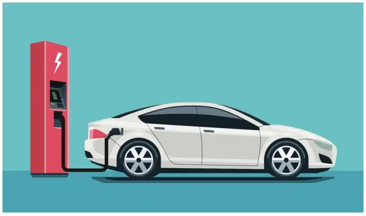
An electric car or battery electric car is an automobile that is propelled by one or more electric motors, using energy stored in batteries. Compared to internal combustion engine (ICE) vehicles, electric cars are quieter, have no exhaust emissions, and lower emissions overall.In the United States and the European Union, as of 2020, the total cost of ownership of recent electric vehicles is cheaper than that of equivalent ICE cars, due to lower fueling and maintenance costs. Charging an electric car can be done at a variety of charging stations; these charging stations can be installed in both houses and public areas.
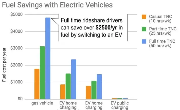
The rapid growth of transportation network companies (TNCs) such as Lyft, Uber and Ride Austin creates a unique opportunity for vehicle electrification, with benefits to cities, drivers and riders. In New York and San Francisco, TNC and cab rides account for 19 percent of all local vehicle miles traveled during weekdays. If half of these TNC drivers went electric, they would offset 1.5 billion pounds of carbon from the atmosphere each year and improve local air quality within the city.
In addition to these environmental benefits, electric vehicles are also significantly cheaper to operate than gas vehicles, despite having a higher upfront price tag. This can be attributed to savings in fuel and maintenance, which scale by how much the vehicle is driven. Highly active TNC drivers are ideal candidates for EVs because they put more miles on their car each year than the average driver. Based on our calculations, full-time TNC drivers working 50 hours a week can save an average of $5,200 per year in total vehicle expenses with an EV as compared to a typical gas vehicle.
The mobility team at Rocky Mountain Institute has been targeting high-utilization vehicles for electrification, as they demonstrate the best economics for EV operation and the highest potential for carbon offset. For the past two years, RMI has partnered with the City of Austin, Texas, to support its mobility goals toward developing shared, electric and autonomous mobility services. Austin offers unique EV charging programs that further bolster the economic savings of driving an electric vehicle.
ELECTRIC CAR AND INDIA:
The Government started Faster Adoption and Manufacturing of Hybrid and Electric vehicles (FAME) scheme which provides incentives for purchasing electric vehicles. Phase I of the scheme lasted from 2015 to 2019, while Phase II began in 2019 and is planned to be completed in 2022.
India sold 69,000 units in 2017–2018 and about 143,000 units in 2018–2019. This indicates a strong growth rate that is likely to accelerate in the next years. Almost 97.5% of all electric vehicles sold in India were two-wheelers, indicating an especially strong market in the two- and three-wheeler segment.
India is the fifth largest car market in the world and has the potential to become one of the top three in the near future — with about 40 crore customers in need of mobility solutions by the year 2030. Many of these “better cars” are likely to be electric.
Since EVs use electricity to charge batteries, and domestic power tariffs range from Rs 8-10 per unit, the monthly running cost is a fraction of cost for petrol or diesel. ... Lower maintenance cost: The build of an electric car is such that you will end up spending less on servicing and upkeep.
BASICS OF ELECTRIC MOBILITY:
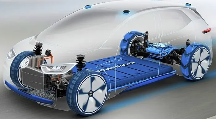
The term electric motor/generator is used instead of . In principle, any electric motor can also be used as an alternator. When the electric motor/generator is driven mechanically, it supplies electrical energy as an alternator.
When the electric motor/generator is supplied with an , it works as a drive. Electric motors/generators used for propulsion are water-cooled. Air cooling would also be possible but complex due to space and the amount of heat generated.
KEY COMPONENTS OF ELECTRIC CAR:
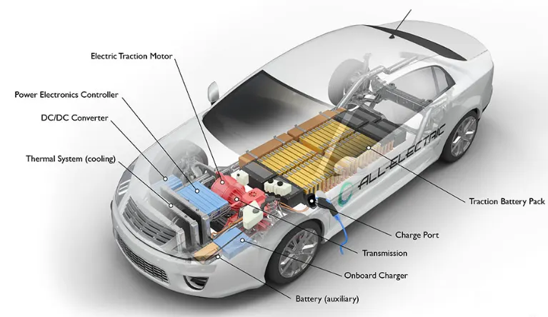
- Battery (all-electric auxiliary): In an electric drive vehicle, the auxiliary battery provides electricity to power vehicle accessories.
- Charge port: The charge port allows the vehicle to connect to an external power supply in order to charge the traction battery pack.
- DC/DC converter: This device converts higher-voltage DC power from the traction battery pack to the lower-voltage DC power needed to run vehicle accessories and recharge the auxiliary battery.
- Electric traction motor: Using power from the traction battery pack, this motor drives the vehicle's wheels. Some vehicles use motor generators that perform both the drive and regeneration functions.
- Onboard charger: Takes the incoming AC electricity supplied via the charge port and converts it to DC power for charging the traction battery. It also communicates with the charging equipment and monitors battery characteristics such as voltage, current, temperature, and state of charge while charging the pack.
- Power electronics controller: This unit manages the flow of electrical energy delivered by the traction battery, controlling the speed of the electric traction motor and the torque it produces.
- Thermal system (cooling): This system maintains a proper operating temperature range of the engine, electric motor, power electronics, and other components.
- Traction battery pack: Stores electricity for use by the electric traction motor.
- Transmission (electric): The transmission transfers mechanical power from the electric traction motor to drive the wheels.
MATLAB MODEL:
Lets Develop a Matlab model for the Electric Car.
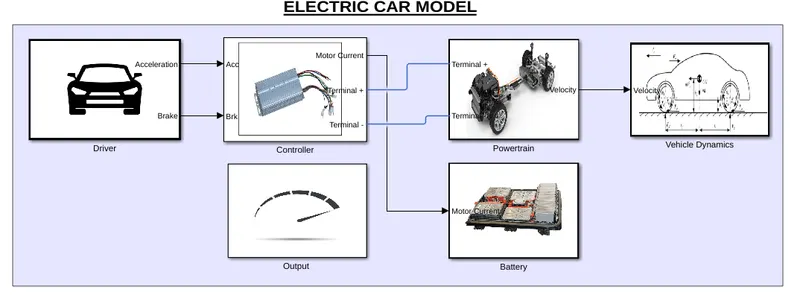
- This is a model representing the Electric Car, where we have all the block performing individual operations.
- we have arranged the blocks as per their functions in a subsystem fashion.
- the input is delivered from the Driver where we will be using drive cycles, and producing output as Acceleration and Braking.
- with Acceleration and braking the output is fed as input to the controller, where the controller uses PWM and H-Bridge for regulating the control signal.
- the controller is connected to the powertrain system and also supplies current to the battery and also consumes energy from battery.
- the Distance will be calculated in the Vehicle dynamics system and output will be displayed in the output block.
- now, lets discuss each and every systems briefly.
DESIGN AND SPECIFICATION:
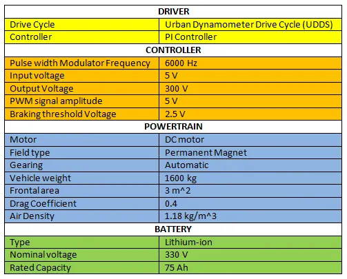
The following table shows the Specification and Design of the Electric Car modelled in MATLAB.
DRIVER SYSYTEM:
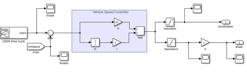
- the drive cycles produce the input speed.
- the drive cycles are customized with the singal builder block.
- this system compares the input speed and the vehicle speed using the sum block.
- for Vehicle speed controll we are using a Vehicle Speed controller in PI fashion.
- If the output is positive speed acceleration is given from the PI controller, and the negative output, deceleration is also given from the controlled.
- The output from the controller is controlled by the saturation blocks by given the upper and lower limits.
- we have kp as 10 and ki as 1, and it tuned in a continuous time based.
- inorder to send the braking in negative we are using a Negative to multiply with the help of gain block.
Drive Cycle:
- Drive cycle is assumed as the driver's input of a vehicle.
- It is the Data representing the driving condition of a driver.
- these drive cycles will have high-speed, low-speed and braking conditions.
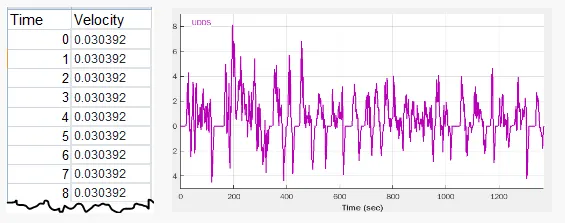
- these drive cycles will be generating signals from the singal builder block.
Urban Driving Drive Cycle (UDDS):
- The ECE is an urban driving cycle, also known as UDC.
- It was devised to represent city driving conditions, e.g. in Paris or Rome.
- It is characterized by low vehicle speed, low engine load, and low exhaust gas temperature.
- The cycle simulates a urban route of 7.5 mi (12.07 km) with frequent stops.
- The maximum speed is 56.7 mph (91.25 km/h) and the average speed is 19.6 mph (31.5 km/h).
CONTROLLER:
The controller transforms the battery's direct current into alternating current (for AC motors only) and regulates the energy flow from the battery.
Controller is a combination of Power electronics and embedded micro-computing elements which make the efficient conversion of energy stored in batteries of an electric vehicle to generate motion
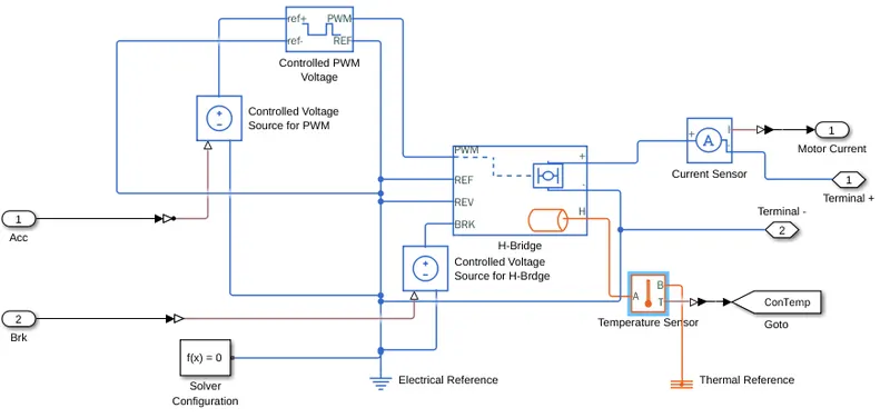
- the output from the driver block i.e. Acceleration and brake is given as the input for the controller.
- controller is one of the main components of the Electric Car that governs it's complete operation.
- Controlled voltage source converts the Acceleration and Brake signal into an equivalent voltage source for the respecitive PWM block and H-Bridge Block.
- The Controlled PWM Voltage block represents a pulse-width modulated (PWM) voltage source for controlling analog circuits with a microcontroller's digital outputs.
- The H-Bridge block represents an H-bridge motor driver,The H-Bridge block output is a controlled voltage that depends on the input signal at the PWM port.
- The Current Sensor block represents an ideal current sensor and the Temperature Sensor block represents an ideal temperature sensor, that is, a device that determines the temperature differential measuring the Heat Generated in the H-Bridge Block.
- The Solver Configuration block specifies the solver parameters that your model needs before you can begin simulation.
- The Electrical Reference block represents an electrical ground. Electrical conserving ports of all the blocks that are directly connected to ground must be connected to an Electrical Reference block. A model with electrical elements must contain at least one Electrical Reference block.
- The Thermal Reference block represents a thermal reference point, that is, a point with an absolute zero temperature, with respect to which all the temperatures in the system are determined.
Settings made inside the blocks:
Double tap on the Block to make the respective changes:
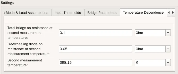
H-Bridge block:
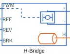
Enable the thermal port of the block by right clicking on the block and select simscape>block choice>thermal port.
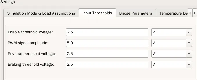
This block represents an H-bridge motor drive. The block can be driven by the Controlled PWM Voltage block in PWM or Averaged mode. In PWM mode, the motor is powered if the PWM port voltage is above the Enable threshold voltage. In Averaged mode, the PWM port voltage divided by the PWM signal amplitude parameter defines the ratio of the on-time to the PWM period. Using this ratio and assumptions about the load, the block applies an average voltage to the load that achieves the correct average load current. The Simulation mode parameter value must be the same for the Controlled PWM Voltage and H-Bridge blocks.
If the REV port voltage is greater than the Reverse threshold voltage, then the output voltage polarity is reversed. If the BRK port voltage is greater than the Braking threshold voltage, then the output terminals are short circuited via one bridge arm in series with the parallel combination of a second bridge arm and a freewheeling diode. Voltages at ports PWM, REV and BRK are defined relative to the REF port.

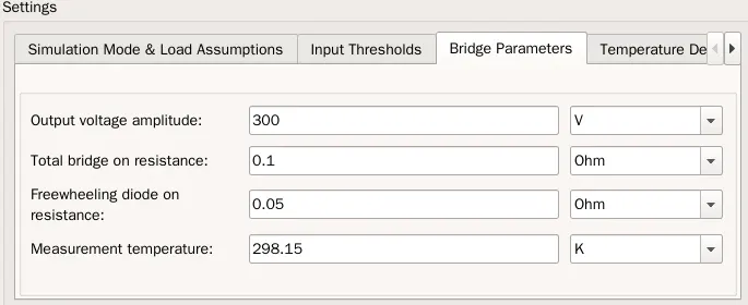
CONTROLLED PWM VOLTAGE BLOCK:

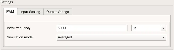
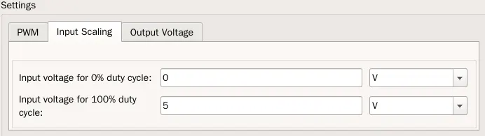
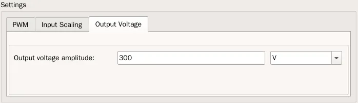
This block creates a Pulse-Width Modulated (PWM) voltage across the PWM and REF ports. The output voltage is zero when the pulse is low, and is equal to the Output voltage amplitude parameter when high. Duty cycle is set by the input value. Right-click the block and select Simscape->Block choices to switch between electrical +ref/-ref ports and PS input u to specify the input value.
At time zero, the pulse is initialized as high unless the duty cycle is set to zero or the Pulse delay time is greater than zero.
The Simulation mode can be set to PWM or Averaged. In PWM mode, the output is a PWM signal. In Averaged mode, the output is constant with value equal to the averaged PWM signal.
POWERTRAIN:
An EV's powertrain is responsible for taking energy stored in the vehicle's battery system and supplying it to the motors. The amount of power that it takes to move a fully loaded vehicle is enormous, and delivery needs to be instantaneous and predictable.
A powertrain is an assembly of every component that pushes your vehicle forward. Your car's powertrain creates power from the engine and delivers it to the wheels on the ground.
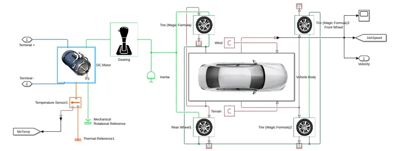
- the H-Bridge's positive and Negative terminal is supplied as input for the DC motor.
- the rotor of the DC motor is connected to the Gear Box, and for speed compounding we are using Interia.
- the hub of the tire is connected to the Vehicle hub and the S is been terminated.
- the wind and terrain is supplied with ps contact block.
- and we are getting output as Vehicle speed.
- The DC Motor block represents the electrical and torque characteristics of a DC motor.
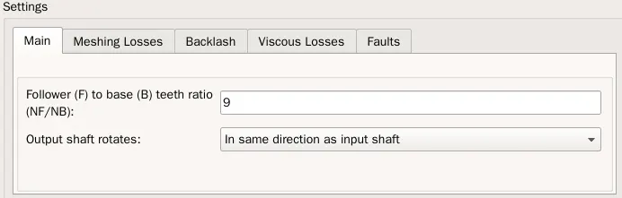
- The Simple Gear block represents a gearbox that constrains the connected driveline axes of the base gear, B, and the follower gear, F, to corotate with a fixed ratio that you specify.
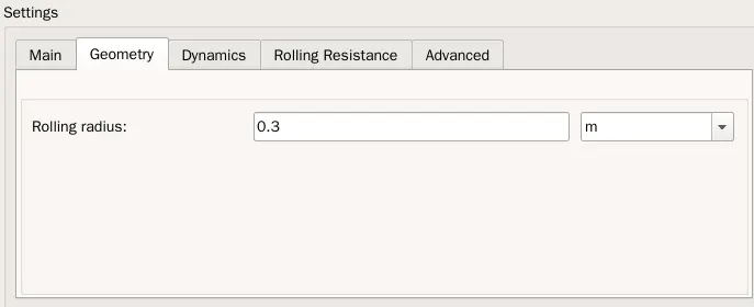
- The Tire (Magic Formula) block models a tire with longitudinal behavior given by the Magic Formula, an empirical equation based on four fitting coefficients. The block can model tire dynamics under constant or variable pavement conditions.
- The longitudinal direction of the tire is the same as its direction of motion as it rolls on pavement. This block is a structural component based on the Tire-Road Interaction (Magic Formula) block.
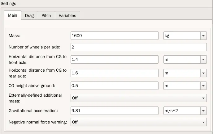
- The Vehicle Body block represents a two-axle vehicle body in longitudinal motion. The vehicle can have the same or a different number of wheels on each axle. For example, two wheels on the front axle and one wheel on the rear axle. The vehicle wheels are assumed identical in size. The vehicle can also have a center of gravity (CG) that is at or below the plane of travel.
- The Temperature Sensor block represents an ideal temperature sensor, that is, a device that determines the temperature differential measured between two points without drawing any heat.
- The Mechanical Rotational Reference block represents a reference point, or frame, for all mechanical rotational ports. All rotational ports that are rigidly clamped to the frame (ground) must be connected to a Mechanical Rotational Reference block.
Settings made inside the blocks:
Double tap on the Block to make the respective changes.
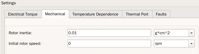
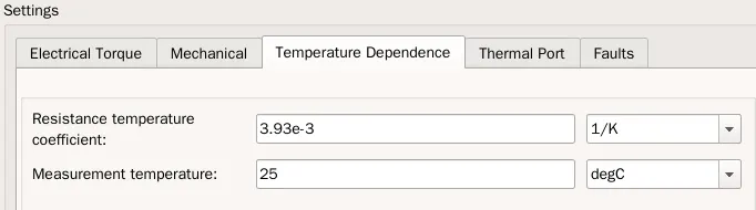
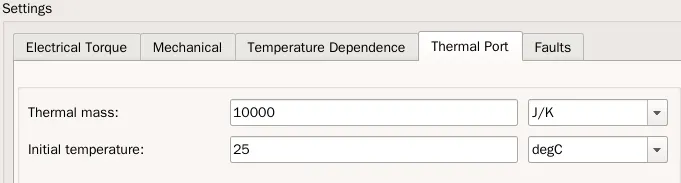
DC Motor:
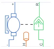
This block represents the electrical and torque characteristics of a DC motor.
The block assumes that no electromagnetic energy is lost, and hence the back-emf and torque constants have the same numerical value when in SI units. Motor parameters can either be specified directly, or derived from no-load speed and stall torque. If no information is available on armature inductance, this parameter can be set to some small non-zero value.
When a positive current flows from the electrical + to - ports, a positive torque acts from the mechanical C to R ports. Motor torque direction can be changed by altering the sign of the back-emf or torque constants.
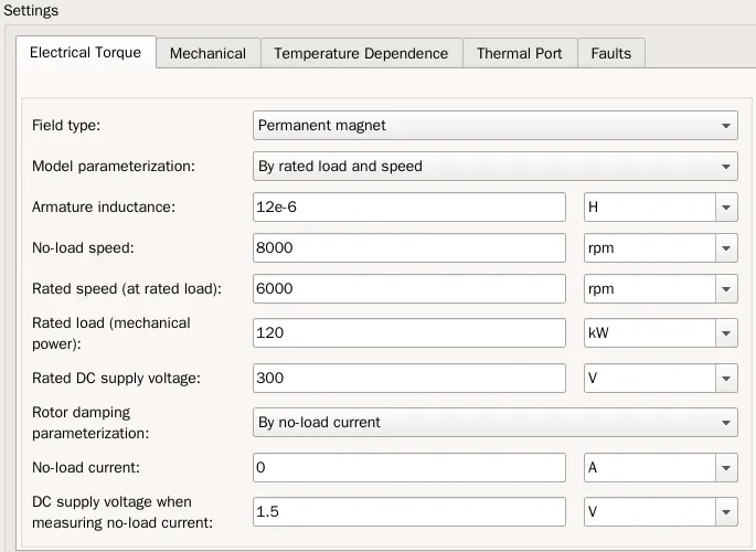
Tire Block:


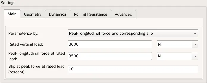
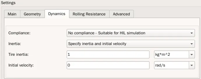
Represents the longitudinal behavior of a highway tire characterized by the tire Magic Formula. The block is built from Tire-Road Interaction (Magic Formula) and Simscape Foundation Library Wheel and Axle blocks. Optionally, the effects of tire inertia, stiffness, and damping can be included.
Connection A is the mechanical rotational conserving port for the wheel axle. Connection H is the mechanical translational conserving port for the wheel hub through which the thrust developed by the tire is applied to the vehicle. Connection N is a physical signal input port that applies the normal force acting on the tire. The force is considered positive if it acts downwards. Connection S is a physical signal output port that reports the tire slip. Optionally expose physical signal port M by setting Parameterize by to Physical signal Magic Formula coefficients. Physical signal port M accepts a four element vector corresponding to the B, C, D, and E Magic Formula coefficients.

GEARING:

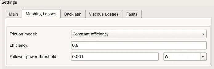
Represents a fixed-ratio gear or gear box. No inertia or compliance is modeled in this block. You can optionally include gear meshing, backlash, and viscous bearing losses.
Connections B (base) and F (follower) are mechanical rotational conserving ports. Specify the relation between base and follower rotation directions with the Output shaft rotates parameter. Optionally include thermal effects and expose thermal conserving port H by setting Friction model to a temperature-dependent setting.
VEHICLE BODY:
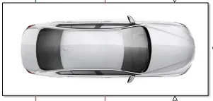
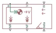
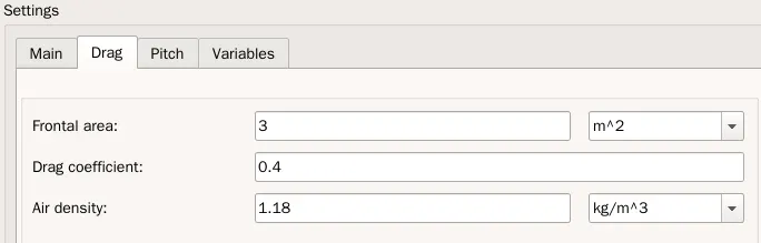
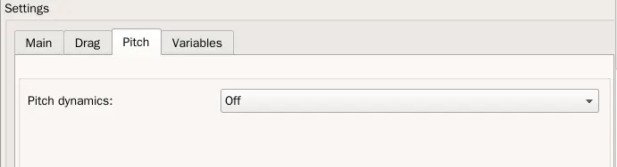
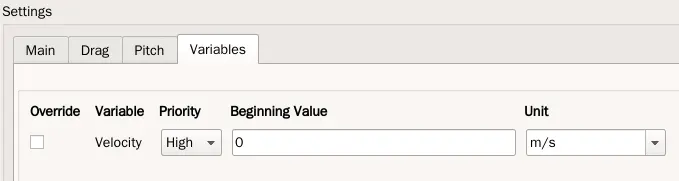
The Vehicle Body represents a two-axle vehicle body in longitudinal motion. The block accounts for body mass, aerodynamic drag, road incline, and weight distribution between axles due to acceleration and road profile. The vehicle can have the same or a different number of wheels on each axle. Optionally include pitch and suspension dynamics or additional variable mass and inertia. The vehicle does not move vertically relative to the ground.
Connection H is the mechanical translational conserving port associated with the horizontal motion of the vehicle body. The resulting traction motion developed by tires should be connected to this port. Connections V, NF, and NR are physical signal output ports for vehicle velocity and front and rear normal wheel forces, respectively. Wheel forces are considered positive if acting downwards. Connections W and beta are physical signal input ports corresponding to headwind speed and road inclination angle, respectively. If variable mass is modeled, the physical signal input ports CG and M are exposed. CG accepts a two- element vector representing the x and y distance offsets from vehicle CG to additional load mass CG. M represents the additional mass. If both variable mass and pitch dynamics are included, the physical signal port J accepts the inertia of the additional mass about its own CG.
BATTERY:
An electric car battery is an energy accumulator that stores electricity for transmission to an alternating or continuous current engine. However, its importance is far greater than this. The battery is what makes these vehicles sustainable, what releases it from its dependence on fossil fuels.
Lithium-ion batteries power things like our phones and electric or hybrid vehicles, and lead acid batteries that are used to start cars with internal combustion engines and store power for the car's lights, radio and other devices. The main difference is the energy density.
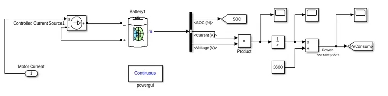
- the input for the battery is from the motor current from the controller block.
- the current source is connected to the battery and we are using a bus selector to find the SOC, Current and voltage.
- but mulitplying current and voltage, the product is intergated and given as Energy Consumped.
- The Controlled Current Source block converts the Simulink input signal into an equivalent current source. The generated current is driven by the input signal of the block. The positive current direction is as shown by the arrow in the block icon.
- The Battery block implements a generic dynamic model that represents most popular types of rechargeable batteries. Here we are using Lithium ion battery.
- The Bus Selector block outputs the elements you select from the input bus. The block can output the selected elements separately or in a new virtual bus.
- The Product block outputs the result of multiplying two inputs: two scalars, a scalar and a nonscalar, or two nonscalars that have the same dimensions.
- The Integrator block outputs the value of the integral of its input signal with respect to time.
- The Divide block outputs the result of dividing its first input by its second. The inputs can be scalars, a scalar and a nonscalar, or two nonscalars that have the same dimensions. This block supports only complex input values at division ports when all ports have the same single or double data type.
Settings made inside the blocks:
Double tap on the Block to make the respective changes.
Battery:

Implements a generic battery model for most popular battery types. Temperature and aging (due to cycling) effects can be specified for Lithium-Ion battery type.
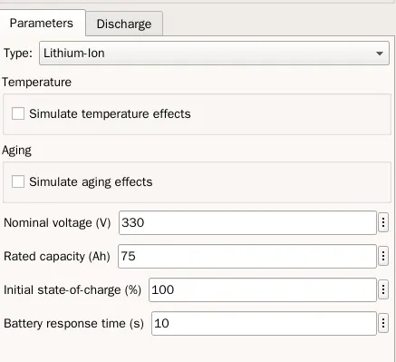
Discharge is determined by the nominal parameters of the battery.
VEHICLE DYNAMICS:
Vehicle Dynamics systems prevent vehicles from spinning or slipping when cornering sharply by controlling vehicle yaw moment, which is generated by braking forces. Thus, it is important to control braking forces depending on the driving conditions of the vehicle.
The vehicle dynamics is the motion of the vehicle generated by the steering action, through which the vehicle is capable of independent motion. This chapter explains the motion of the vehicle for a given steer input, and explains the mechanics of vehicle motion.
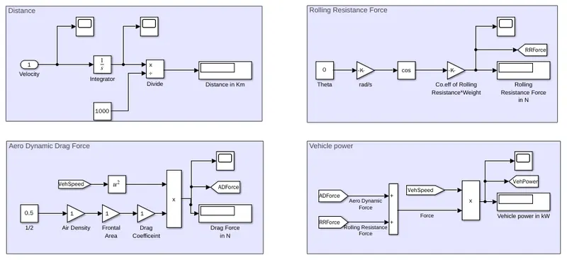
- In the Vehicle dynamics block we will be calculating the Distance travelled by the Vehicle, Rolling Resistance Force, Drag Force and Vehicle Power.
Distance:
- we know that the Distance is obatined by Intergating Velocity.
- the solutions will be displayed in the display block.
- for meter to kilo meter conversion we are dividing Velocity in m with 1000 to get Km.
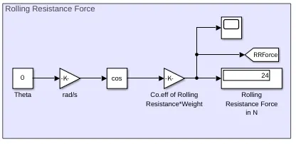
Rolling Resistance Force:
- Rolling resistance takes on an even greater importance for electric cars.
- Lower rolling resistance means increased electric range and higher efficiency, while also contributing to your car's overall sustainability.
- using the formula `Cr*M*cos theta` , we can Calculate the Rolling resistance force
- where,
- Cr is the Rolling resistance Coefficient.
- M is the Weight of the Vehicle.
- Theta is the Gradient Angle.
- we will be using the formula with respective blocks.
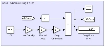
Aero Dynamic Drag Force:
- the aerodynamic drag force parameters which represents the air resistance on an electric vehicle motion performance.
- these parameters are the aerodynamic drag coefficient, the equivalent frontal area of the vehicle, and the head-wind velocity.
- using the formula `1/2 * rho*a*V^2 *d`, we can calculate the Drag Force.
- where,
- `rho` is the density of air in kg/m^3.
- a is the frontal area.
- V is the velocity
- d is the drag coefficient.
- we will be using the formula with respective blocks.
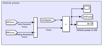
Vehicle Power:
- Vehicle power demands are weight sensitive and encompass the engine power used to overcome inertia, rolling resistance, aerodynamic drag, drivetrain losses, and the power used for auxiliary loads.
- using the formula Total Force x Velocity we can calculate the drag force.
- where, Total Force is the sum of Rolling resistance force and Drag force.
- we will be using the formula with respective blocks.
OUTPUT:
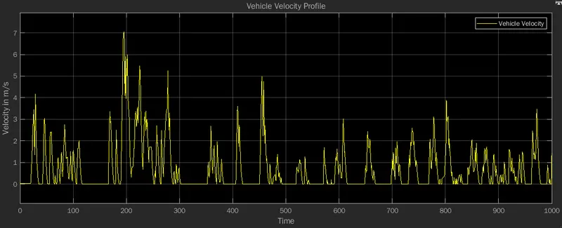
- from the velocity profile graph we can understand the characteristics of Vehicle Velocity.
- A velocity vs time graph is a type of graph that compares how velocity changes over a period of time.
- This type of graph can be used to understand both the velocity of the Electric car, the direction it is moving, its acceleration and the displacement of the Car.
- we can see the presence of Acceleration and Decceleration depends on the Drive cycle which we provided as an Input.
- the inital velocity as 0 m/s at 0 s.
- we can see there is lot of acceleration and decceleration involved, which produces spikes in out graph.
- the peak response it at 7 m/s at 200 sec.
- so the velocity sticks with the drive cycle.
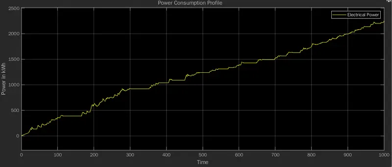
- from the power consumption profile we can understand the energy consumption of the system.
- the area under the graph gives the energy generated by the Battery.
- the power is consumped as per the drive cycle we gave as an input.
- at intial 0 energy is consumed at 0 s, and when time increases the energy increase along with it.
- we can see ripples rising and falling in the Graph.
- that is because of the drive cycle values we have given as input.
- and redistribution of energy occurs due to the regenerative braking.
- so from the Graph we can say the power consumper is 25 kWh.
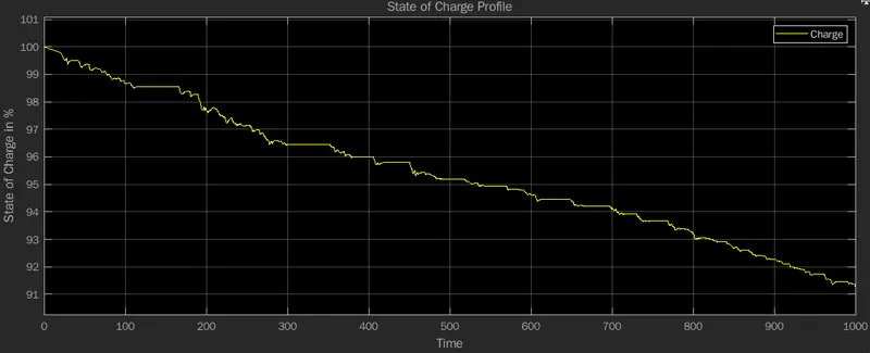
- From the SOC profile graph we can understand the charging level.
- State of charge (SoC) is the level of charge of an electric battery relative to its capacity.
- the vehicle starts at 100 % charge and reduces to 98 percentage in 1000 s.
- since there is acceleration/decceleration involved, the battery gets charged as the vehicle deccelerates.
- this Drive cycle is more efficient than compared to the previous drive cycle.
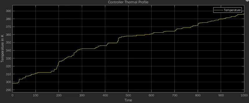
- the controller thermal profile graph explains us the Rise/Fall in temperature of the Controller.
- we can see the initial temperature is 298 K and increases as time increases.
- from the graph we can predict the controller temperature at Vehicle operation will be 386 K.
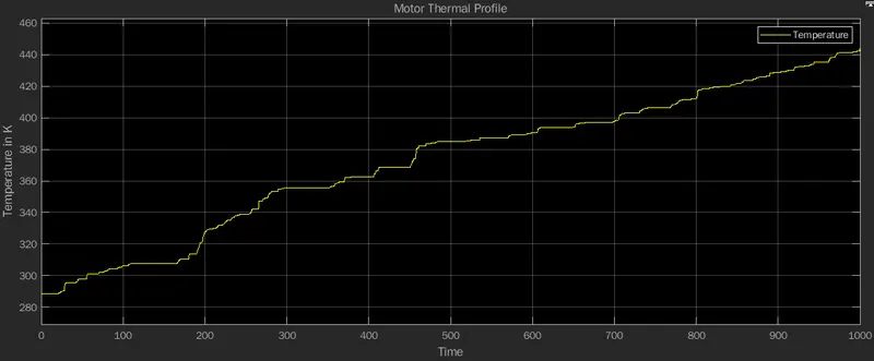
- the Motor thermal profile graph explains us the Rise/Fall in temperature of the Motor.
- we can see the initial temperature is 290 K and increases as time increases.
- from the graph we can predict the Motor temperature at Vehicle operation will be 440 K.
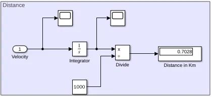
- the average Distance travelled by the vehicle is 0.7 km for 1000 s in the UDDS Drive Cycle mode.
- the Rolling Resistance of the car is 24 N.
- the Drag force for the car is 1.044 N.
- the Vehicle power is 36.18 kW.
RESULT:
- Thus the Matlab Model of an Electric Car showing all its major components as a subsystem starting from the motor to the vehicle dynamics is modelled successfully.
- The Vehicle Parameters are analysed and estimated.
- The entire model by changing the parameters corresponding to various subystem like, DC motor, H-Bride, Vehicle Body, so as to identify the dependenices of the subsysytem parameters over the entire MATLAB model is simulated successfully.
- A Vehicle control system using PI is introduced to reduce the deviation of the actual vehicle velocity with respect to the reference velocity which identifes as an error to the system and minimize the error to some extent.
POPULARITY OF ELECTRIC CARS IN INDIA:
- Electric vehicles may be still some time away to become mainstream in India, but there are enough indications that the demands are rising. That is what the government claims, citing data from its e-vahan portal.
-
According to data available, electric vehicle demands in India has grown significantly, double to be precise, in the last three years.
-
India had 69,012 units of electric vehicles on road in 2017-18. The number increased to 143,358 units in 2018-19 and then to 167,041 units in 2019-20.
-
During a written reply to a question on e-vehicles in the Lok Sabha, Minister of State for Heavy Industries Arjun Ram Meghwal shared this information, saying that the number of registered electric vehicles, available through government data, has seen a consistent increase in the last three years.
The government attributes the rise in demand for electric vehicles to rising fuel prices and government's push to adopt electric mobility to reduce vehicular pollution. -
Several steps and initiatives have been taken, not only by Centre but some of the state governments too, to promote electric vehicles.
-
For instance, the Centre has reduced GST rate on electric vehicles from 12 per cent to 5 per cent and GST on setting up EV infrastructure like charging stations from 18 per cent to 5 per cent. Meanwhile, a few state governments, including the Delhi government, have announced their own electric vehicle policies that are aimed to incentivise those who adopt e-mobility.
-
Minister of Heavy Industries and Public Enterprises, Prakash Javadekar has also said that as part of the second phase of the FAME India scheme, the government will focus on switching public and shared transport in India to electric by subsidising electric buses, cars and two-wheelers.
-
The FAME II scheme aims to put around 10 lakh electric vehicles on road by March, 2022.
-
Electric carmakers in India have been raising concerns about the target for quite some time now. According to the Society of Manufacturers of Electric Vehicles (SMEV), the criteria under the scheme made electric two-wheelers unaffordable despite the subsidies offered. It had requested the government to either rejig the FAME-II scheme or reintroduce FAME-I before fixing the issues.
-
Despite the rise in demand for electric vehicles in India, the target of 10 lakh EVs on road still seems a bit unrealistic. However, the government is hopeful that the demand will pick up further in coming days when the infrastructure improves and the price of EVs come down. Union Minister Nitin Gadkari had urged EV makers to forgo profit for now till customers begin to adopt electric mobility more regularly.
FROM THE NEWS:
- Tata Motors has become the country’s second-largest auto manufacturer and it has also claimed the throne of the largest mass-market EV producer in the past year. The Indian automaker which has enjoyed massive success with its early mover advantage in the EV segment is now looking towards a very optimistic future and is planning to produce more than 50,000 electric vehicles in the coming fiscal year.
-
FedEx Express has announced the start of electric vehicle (EV) trials in India as part of its global goal to achieve carbon neutral operations by 2040.
-
Mercedes-Benz India plans to bring to the market the locally assembled EQS electric sedan in the fourth quarter of 2022 to add to the all-electric SUV EQC, which was launched as a fully imported unit in October 2020 priced at ₹1.07 crore.
CONCLUSSION:
Thus the Project 2 on Electric Car is modelled successfully and the output is verified.