Week - 4
AIM:
To Implement control logic of a “washing machine” using Stateflow as per given sequence, and To Make a Simulink chart for the “Gear shift” logic as per Given conditions.
1.Implement control logic of a “washing machine” using Stateflow as per given sequence:
- If the power supply is available, the system gets activated
- If the Water supply is not available, stop the process & indicate through LED
- Soaking time should be 200s followed by Washing time of 100s.
- Then rinsing happens for next 20s & dryer runs for 50s.
WORKING PRINCIPLE OF A WASHING MACHINE.
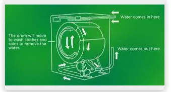
- The process uses the centrifugal force to both clean and dry the clothes in the machine.
- Centrifugation is the process with which we can separate particles depending on their size, shape and density from a solution.
- So, we can say that the working principle of the washing machine is centrifugation.
STATE-FLOW:
- Stateflow is a control logic tool used to model reactive systems via state machines and flow charts within a Simulink model.
- Stateflow uses a variant of the finite-state machine notation.
- which enables the representation of hierarchy, parallelism and history within a state chart.
CONTROL LOGIC OF A WASHING MACHINE USING STATE-FLOW:
Condtions Given:
- If the power supply is available, the system gets activated
- If the Water supply is not available, stop the process & indicate through LED
- Soaking time should be 200s followed by Washing time of 100s.
- Then rinsing happens for next 20s & dryer runs for 50s.
SIMULINK MODEL:
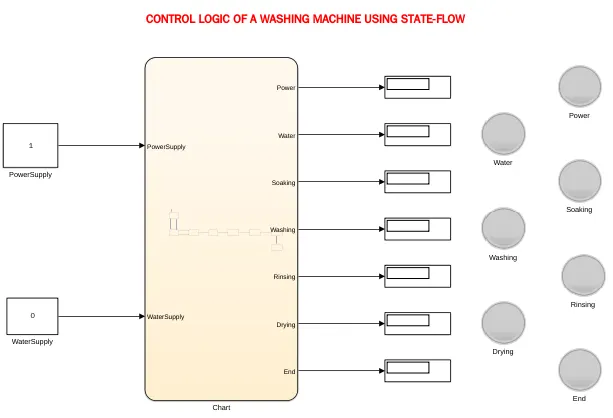
- this simulink model consist of 2 constants blocks represting the power supply and water supply
- a chart where the State-flow logic is contained.
- A Dispaly is connected to the output ports of the display
- then a lamp is connected to the display
- the lamp represent two conditions OK and NO-GO.
STATE-FLOW CHART:
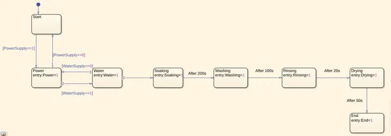
- The State flow chart represents the control logic of the washing machine.
- initially powersupply of value 1 is given to the Power block, the power block accepts the value only if the value is 1,
if it is less than zero the powerblock returns the value back to the source. - the same logic is applicable to all the blocks.
- as per the given condition the washing process starts of 200 secs if value is 1 from water supply the washing process starts,
if water is not avaible then it will be a NO-GO conditions and the block will not accept the Value. - after washing, rinsing starts after 100 s same conditon is applicable here.
- and after Rinsing 20s later drying starts and the process ends in 50 secs.
CASE 1: What if only water supply is available
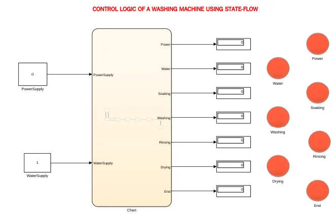
- we can see that there is no operation carried out due to the absense of Power supply.
- all the lamp are showing Red color which represents a NO-GO condtion
CASE 2: What if only power supply is available
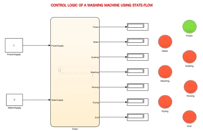
- On observing the case 2 condtion we can also see that there is no operation carried out due to the absence in Water Supply.
- only the Power lamp is showing green color which represents a OK condition.
- and the rest are showing a NO-GO condition due to the absence of Water supply,
CASE 3: What if both Power supply and water supply is available.
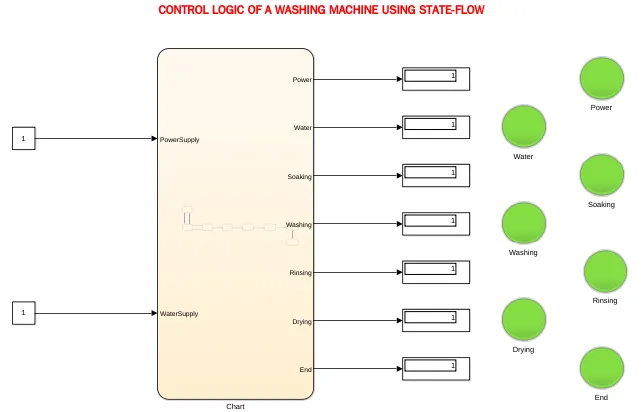
- On observing the case 3 study we can see that the operation is running fine.
- The Green light in the Lamp indidcates that the washing machine is in OK Condition.
- So it is understood that both the water and power supply is vital to the function of the Washing machine.
- Thus the control logic of washing machine using State-flow Follows.
2. Make a Simulink chart for the “Gear shift” logic :
The given conditions are per the Objective
Speed Range(kmph) Gear
0 to 15 1
16 to 25 2
26 to 40 3
41 to 60 4
Above 61 5
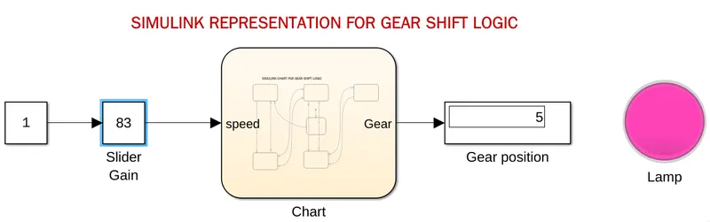
SIMULINK MODEL:
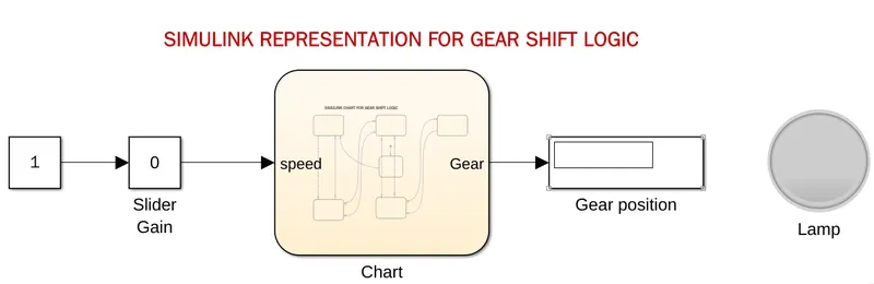
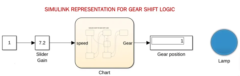
- this simulink model represents the Gear shift Logic behind a car.
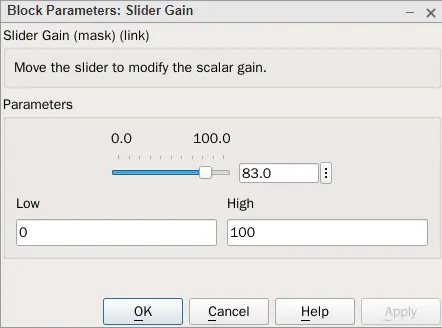
- a constant block is connect to a slider gain block, where The Slider Gain block performs a scalar gain that you can modify during simulation.
- the slider gain block is connected to the gear logic chart, which is connected to a Display.
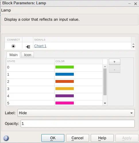
- a lamp is connected to the display which indicates the gear position through different light colors.
SIMULINK CHART FOR GEAR SHIFT LOGIC:
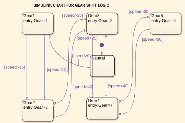
- the Simulink chart represents the Gear shift logic of a Vehicle.
- the source begins with the nuetral condition where the vehicle has no speed and no gear condition.
- as per the given condition the first gear varies from 0 to 15 kmph, so if the input speed from the slider gain block
falls from 0 to 15 kmph the display shows 1st gear. - if the speed is less than 0 the gear is neutral, and if it is high than 15, the gear shifts to 2nd gear.
- the same logic is applicable to rest of the gears.
- the second gear varies from 16 to 25 kmph, so if the input speed from the slider gain block
falls from 16 to 25 kmph the display shows 2nd gear. - if the speed is less than 16 the gear goes to 1st gear position, and if it is high than 25, the gear shifts to 3rd gear.
- the same logic is applicable to rest of the gear.
- lets set the lamp colors for each gears.
- and configure slider gain block where we move the slider to vary the speed form Low to High.
CASE 1: lets run a simulation with speed limit between 10 kmph to 15 kmph and check the Gear position:
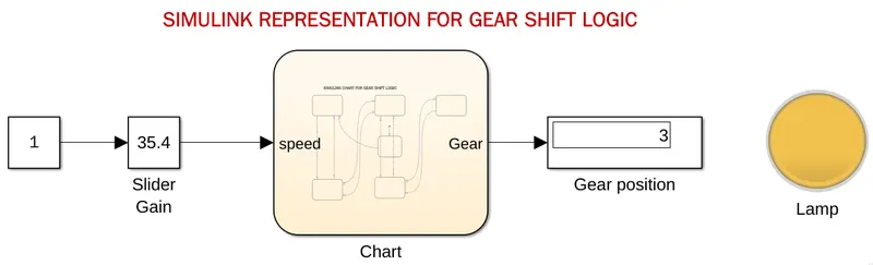
CASE 2: lets run a simulation with speed limit between 26 kmph to 40 kmph and check the Gear position:
CASE 1: lets run a simulation with speed limit above 60 kmph and check the Gear position:
RESULT:
Thus the Control logic of a “washing machine” using Stateflow is completed successfully as per given sequence, and the Simulink chart for the “Gear shift” logic is also completed successfully as per Given conditions and the output is verified.