Project 1 Mechanical design of battery pack
AIM:
to design a battery pack of capacity 18 kWH with the ANR26650M1-B.
BATTERY PACK:

- A battery pack is a set of any number of (preferably) identical batteries or individual battery cells.
- a cell is a single unit device which converts the chemical energy into electrical energy. It is the collection of electrochemical cells which either connects in series or in parallel.
- a Battery is a device which converts chemical energy into electric energy and also A battery is an energy source consisting of one or more electrochemical cells and terminals on both ends called an anode (-) and a cathode (+).
- They may be configured in a series, parallel or a mixture of both to deliver the desired voltage, capacity, or power density.
- The term battery pack is often used in reference to cordless tools, radio-controlled hobby toys, and battery electric vehicles.
- Batteries work based on the principle of a voltage differential, and at high temperatures, the electrons inside become excited which decreases the difference in voltage between the two sides of the battery.
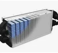
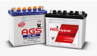
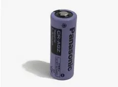
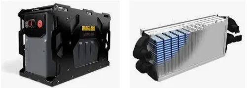
- the above images represents the picture of a electric vehicle battery pack, a battery and a cell.
- we can see that the application of batteries has been increased from normal toy cars to super charged Electric cars and Hybrid cars.
- the most typical type of battery packs is lithium ion due to thier high power density.
- Here we are using lithium iron phosphate cell.
CONSTRUCTION OF A BATTERY PACK:
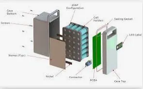
now we are going to dicuss about the Construction, Parts and the factors to be considered while designing a battery pack.
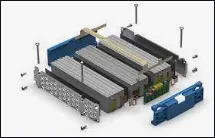
Lets begin with:
- the purpose of a battery pack is to provide a convenient integrated power source for portable applications.
- The pack may fulfil several functions:-
- It enables higher voltage or higher capacity batteries to be built up from low voltage, low capacity cells.
- It houses a cell or a bank of cells together with the associated interconnections in a single convenient pack.
- It accommodates any necessary monitoring and electronic protection devices or circuits within the pack.
- It can accommodate additional circuitry such as indicator lights, heaters, cooling ducts and solar panels.
- It matches and meshes with the cavity in the product which the battery is intended to power providing both electrical and mechanical interfaces.
- It can provide unique electrical and mechanical interfaces to ensure compatibility both of the battery with the intended product and the charger with the battery.
STEP 1 :
the first step in the design of the pack is to determine the configuration (i.e) how many cells overall,how many are in series, and how many are in paralled. This is the foundation of the design process, since all other design decisions follow from the cell configuration
Cell Configuration:
- The ultimate shape and dimensions of the battery pack are mostly governed by the cavity which is planned to house it within the intended application.
- This in turn dictates the possible cell sizes and layouts which can be used.
- Prismatic cells provide the best space utilisation, however cylindrical cells provide simpler cooling options for high power batteries.
- The use of pouch cells provides the product designer more freedom in specifying the shape of the battery cavity permitting very compact designs.
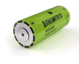
- we are using cylindrical cells
Cells in Series:
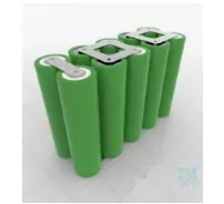
- Cells combined in series connection can achieve hgiher operating voltages by connecting the positive terminal of one cell to the negative terminal of the next cell.
- Series connection compounds Voltage.

Cells in paralled:
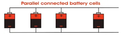
- Cells combined in parallel connection can achieve higher operating capacities by connecting like-polarity terminals of adjacent cells to each other.
- Paralled connection compounds capacity.
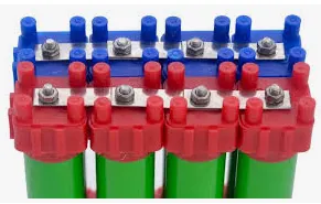
Lego connector:
- A lego connector is used because with this the cells are connected simply.
- it is the best electrical and mechanical connection.
STEP 2:
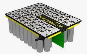
- design a mechanical structure around the cells to support and protect them. This step requires knowledge of electrical, mechanical and thermodynamic requirments and properties of the cells, application and the materials used in the pack.
- the mechanical interconnects are present to prevent accidental short circuits.
- these mechanical interconnects should be design in a size which carry the expected maximum rated current for both the maximum time and ambient temperature in which the pack is expected to operate.
STEP 3:
- design the protection of cells, particiularly electric protection.
- The pack must be protected from inadvertent short circuits internaland external to the packs as wll as excessice chraging and discharging imposed on its terminals.
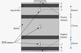
- the cell vents, located on the end cap(s) of the cells (on the POSITIVE side of the cell), should be blocked by any mechanical means.
- Blocking the cell vent and then sufficiently abusing the cell so as to build up pressure in the cells prevents the cell from properly venting.
- An ESS designed to install cells end-to end needs at least 1 mm of space between the cells to allow the vent to open under fault conditions
STEP 4:
- design a control system than monitors and manages the cells, keeping them from being damanged and maintaing the pack at peak performance.
- To safely use the energy stored in cells, the Li-ion battery pack needs a Battery Management System (BMS).
- The BMS is the control system of the pack and can be simple or complex, depending on the need of the battery pack and host application. Returning to the car analogy, think of a battery pack's BMS like a car's control system.
- In a car, the control system shuttles fuel from the fuel tank to the engine to be utilized in a controlled and safe manner and notifies the user of any issues (i.e. low fuel).
- The BMS performs a similar role by safely regulating the energy carried through the cells inside a battery pack. It can also communicate information back to the end user (i.e. low battery life).
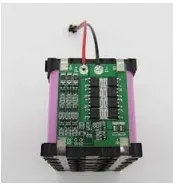
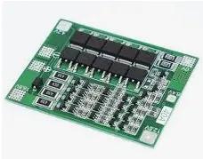
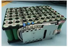
- There must be a connection between the cell and the BMS in order to interface with each other.
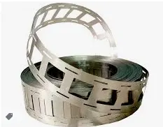
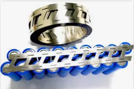
- Nickel strips are the preferred method of connecting a battery cell to the control system.
- A thin strip of nickel is capable of carrying high amounts of current, is flexible, durable, and can be attached to the cell without the use of excessive heat.
- These strips provide a safe means of getting the "fuel" out of the "fuel tank" to use it in a safe manner.
- conductive metal strips are spot welded between all the cells of an electric bicycles pack.
- Nickel is the material of choice due to its low relative resistance and ease of spot welding.
- Steek is cheaper than nicle, which is why many vendors sell nickel coated steel strips.
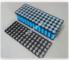
STEP 5:
- Lastly, all these components need to be packaged so that the battery pack can be installed into a device.
- Once all components are properly placed and connected to one another, they are sealed with either shrink wrap or a hard case.
- The housing ensures that the components remain safely located and provides a clean package for the eventual use by an end user.
- The type of housing depends on where the battery pack will be located inside the device
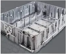
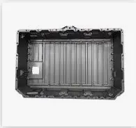
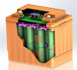
Images of a Completely Built Battery Pack:

LITHIUM ION PHOSPHATE CELL:
- The lithium iron phosphate battery or LFP battery, is a type of lithium-ion battery using lithium iron phosphate as the cathode material, and a graphitic carbon electrode with a metallic backing as the anode.
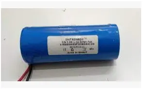
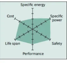
- based on lithium iron phsophate chemistry (LiFePo4), the cells are inherently safe over a wide range of temperatures and conditions.
- whether the application requires outstanding cycle life or stable float reliability, the 26650 cells are suitable for a wide variety of power, pulse or stand-by applications.
DIMENSIONS OF A ANR26650M1-B CELL :
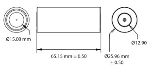
SPECIFICATIONS OF ANR26650M1-B CELL:
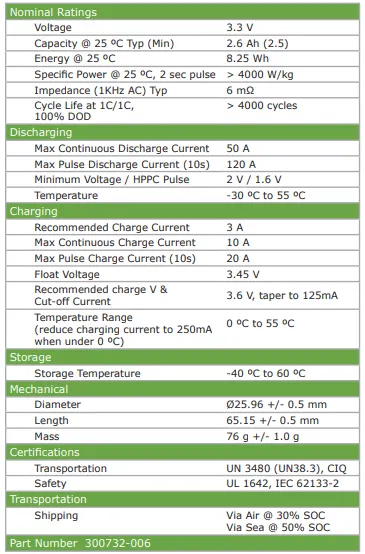
CALCULATIONS:
- most of the battery pakcs are combination of series and parallel connections
- single cell cannot meet the capacity demanded.
- series and parallel connection is compulsory.
- larget battery pack have mutiple modules.
- togetherness helps to build a larger battery pack.
- Series connection compounds voltage. while parallel connection compounds current(capacity)
The objective is to design a battery pack of 18 kWh.
18 kWh is corresponding to Energy to Range and it is a product of Voltage(V) and Capacity(C)
let us assume the Total Voltage of battery pack as 160V, basically this depends upon the motor power. We can decide the value according to the motor.
no of cells required for series connection = Total Voltage of Battery pack / individual voltage of cell
= 160/3.3
`approx` 48.
so 48 cells are required for a series connection.
to find the no of cells required for parallel connection we need to calculate the total cpacity of the batery pack
total capacity = Energy required / Total Voltage. we know from the objective that 18 kWh is the energy required. lets take the value in Watts.
= 18000 / 160
` = 112.5 Ah.
now we know that the total capacity of the battery is 112.5 Ah.
no of cells required for parallel connection = Total capacity / individual capacity of the cell.
= 112.5 / 2.5. For safe operating area we assume individual capacity of the cell as 2.5 Ah.
`approx` 45.
so 45 cells are required for a parallel connection.
now we know that the 18kWh battery pack required 48 cells connected in sereis and 45 cells connected in parallel.
`Voltage across the series connection = 48*3.3
`approx`160 V
Current across the parallel connection = 45*2.5
`approx` 112.5 Ah
we know that 18kWh is a product of Voltage (V) and Capacity (Ah)
Power = Voltage * Current
= 160 * 112.5
= 18,000 Wh or 18kWh , We know that 1,000 W = 1kW.
RESULT:
Thus a 18kWh battery is designed and the Design Procedure is explained successfully, and the Output is verified.