Week -2
AIM:
To Make a Simulink model of Doorbell using solenoid block and Use a thermistor to sense the temperature of a heater & turn on or turn off the fan.
TO BEGIN WITH:
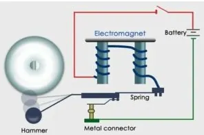
- The heart of a doorbell is an electromagnet.
- When you press a doorbell button, you complete an electrical circuit that allows household
- electricity to flow through the doorbell's internal electromagnet.
- The magnetic field generated by the electromagnet is then used to power a mechanism that creates the doorbell sound.
PRINCIPLE BEHIND DOOR BELL:
- Running electrical current through wire creates a very small magnetic field around the wire.
- Coiling the wire amplifies this magnetic field, so it has a substantial effect on any magnetic objects around it.
- Just like the magnetic field around a permanent magnet, the magnetic field of an electromagnet has a polar orientation -- a "north" end and and a "south" end -- and it is attracted to iron objects.
- When you hold down a doorbell button, it closes an electrical circuit so that household current
flows through the electromagnet (or electromagnets) by way of a transformer. - The transformer is a simple device that takes the 120-volt household current and steps it down to a 10-volt current (see Inside a Power-Cube Transformer to find out how).
- This current is then passed through the electromagnet wire.
- The magnetic field of the electromagnet is put to work to drive some sort of a noisemaking
apparatus.
SIMULINK MODEL:
- We know that, when the switch is closed the electromagnet receives electrical power from the battery and pulls the metal arm to hit the bell producing sound.
- Now lets Create a situation as per the objective in which the switch is closed for 2 seconds and then released. Observe the physical movement of the plunger.
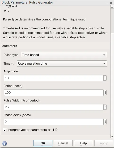
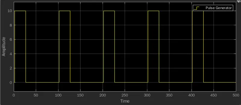
- A pulse generator block generates Square waves in a Regular interval.
- Time-based is recommended for use with a variable step solver, while Sample-based is recommended for use with a fixed step solver or within a discrete portion of a model using a variable step solver.
- now lets fix the parameters as per the objectives, the phase delay as 2s, pulse width as 25%, period as 100s, amplitude as 10.
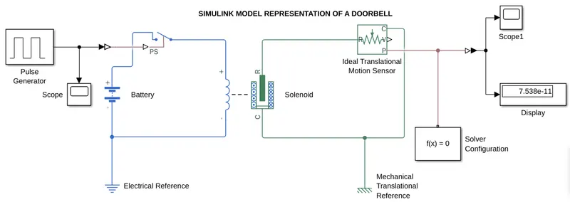
- the positive terminal of the battery is connected to the switch and the negative terminal is connected to the electrical reference.
- the switch block used is supplied with signals from the pulse generator in a square wave form.
- the switch is in open condition, if the pulse wave form is greater than the given parameter then the switch will close.
- the solenoid block is connected with switch and battery.
- the port c is connected with mechanical reference.
- the ideal translational motion sensor is connected with the solenoid block R to sense the movement of the plunger.
- we have 2 scopes one connected with the Pulse Generator and other connected with the translational motion sensor.
- since the physical network requires solver setting information for simulation so we are using solver configuration.
OUTPUT:
Observation:
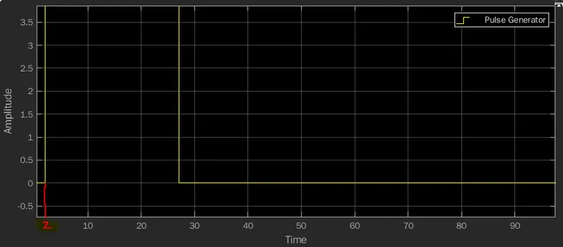
- the resultant graph is displayed in the scope based on the input data that is given from the Pulse Generator Block.
- as per our objective the circuit to be closed only in the interval of 2 seconds and then released.
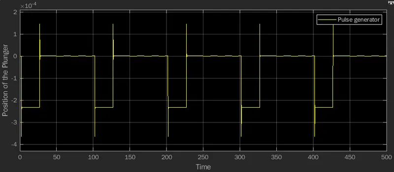
- when the switch is closed the solenoid blocks recieves electrical power from the battery and the plunger move from port R to C to hit the bell and produce sound.
- at 2 seconds the amplitude maintained is 1 and then again for next 2 seconds the pulse is maintained zero.
- the position of the plunger is obtained by using the ideal translational motion sensor.
- the Electromagnetic interferences are captured with the pulses in the graph in a spike like representation.
SIMULINK MODEL USING A THERMISTOR:
- Now lets create a simulink model using a thermistor to sense the temperature of a heater & turn on or turn off the fan.
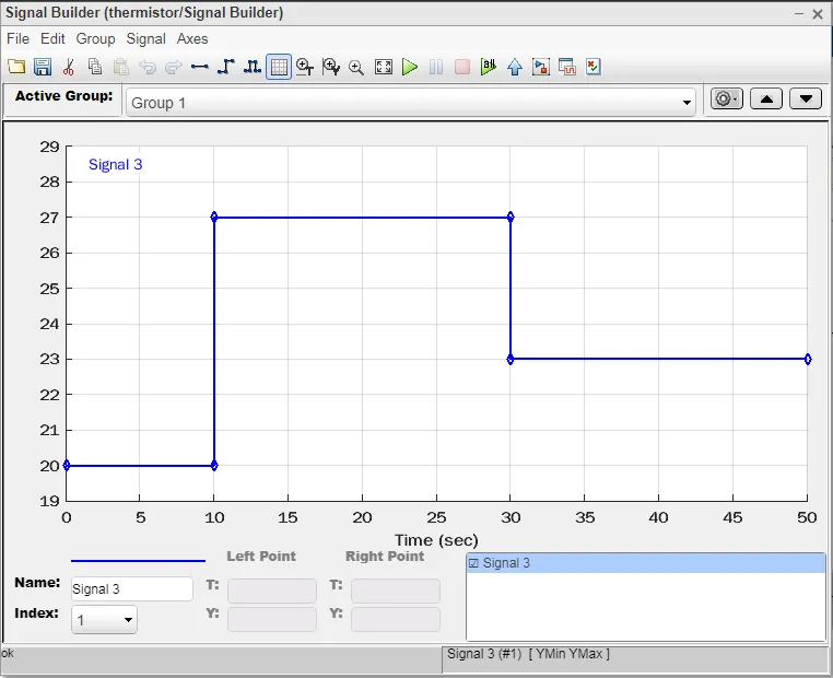
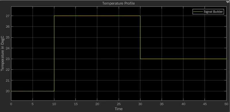
- Temperature source: 20 °C from 0 to 10 seconds, 27 °C from 10 to 30 seconds, 23 °C from 30 to 50 seconds.
- Fan conditions: ON if the temperature above 25 °C, OFF otherwise.
- Thermistor is a type of resistor whose resistance varies with temperature.
- There are two types of thermistors namely PTC and NTC.
- In PTC thermistor, resistance increases with increase in temperature.
- in NTC resistor, resistance decreases with increase in temperature.
SIMULINK MODEL:
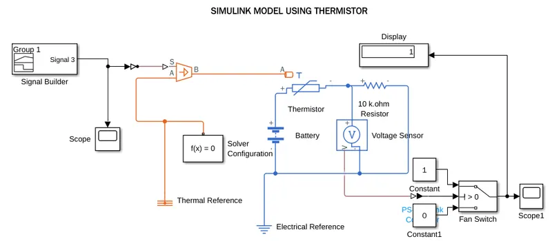
- we give the input signal using the signal builder block.
- the input signal is being fed in the signal builder block according to the conditions given.
- 20 °C from 0 to 10 seconds,
- 27 °C from 10 to 30 seconds,
- 23 °C from 30 to 50 seconds.
- the singal is being fed to the S port of the controlled temperature source using the Simulink PS converter block.
- the A port is connected to the thermal reference and the B port is connected to the thermal port T of the thermistor.
- a resistor of 10 K ohm is connected in series with the thermistor.
- Voltage sensor is connected in parallel to the resistor.
- A battery is connected in this circuit followed by a electrical reference.
- The output from voltage sensor is being fed to display block using a PS-Simulink converter.
- The display block displays the threshold value being measured by the voltage sensor.
- This threshold is being fed to a 3 pin switch.
- Constants 0 and 1 are being fed to the other two pins in the switch.
- Finally a scope is connected to the switch.
OUTPUT:
OBSERVATION:
- The graph above shows that from 0 - 10 seconds, the temperature is 20°C and the fan is off condition.
- The fan's condtion gets turned on from 10 - 30 seconds where the temperature is 27°C
- The fan goes back to turns off condtion when the temp is less than 25°C.
- The stop time is 50 seconds
- In the above plot at 30 seconds, the fan goes off again as the temperature reaches 23°C.
RESULT:
Thus the Simulink model of Doorbell using solenoid block is completed successfully and a thermistor to sense the temperature of a heater & turn on or turn off the fan is also modelled and completed successfully and the output is verified.