Project 1 : CFD Meshing for Tesla Cyber Truck
Aim:
Performing topological cleanup and surface mesh on tesla cyber truck and on a wind tunnel based on selected target length values of its different components using element type as Tria, as well as appropriate selection of the volume that contains the vehicle and its surroundings with the wind tunnel for volumetric meshing in ANSA-CFD
Objectives:
For the given model, check and solve all geometrical errors on half portion and Assign appropriate PIDs. Perform meshing with the given Target length and element Quality criteria. After meshing the half model, Do symmetry to the other side.
- Target lengths for the different parts of a model are as follow:
- Body - 3 mm
- Window - 4 mm
- Lights - 4 mm
- Rims - 4 mm
- Tyre inside layer - 1 mm
- Tyre outside layer - 2 mm
Procedure:
Topo Cleanup
Open Ansa Software and load the geometry
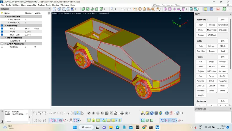
Apply topo for whole model
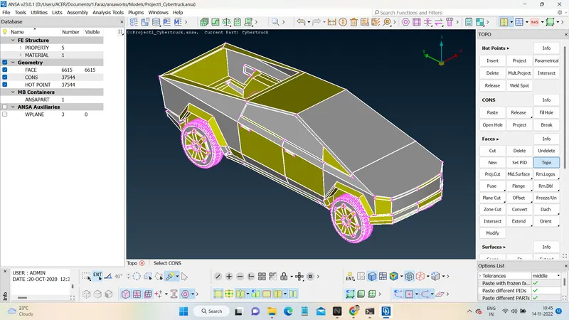
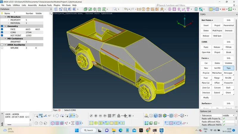
There are many errors on model but first we will cut the model into half. So that after the cleanup and meshing we can just copy the other side through symmetry
Select Plane Cut > 3point plane, Select any three points on where the plane is and apply.
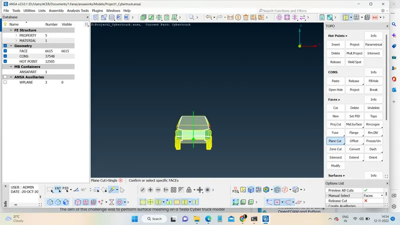
We have a symmetric model with double cons dividing it in the middle
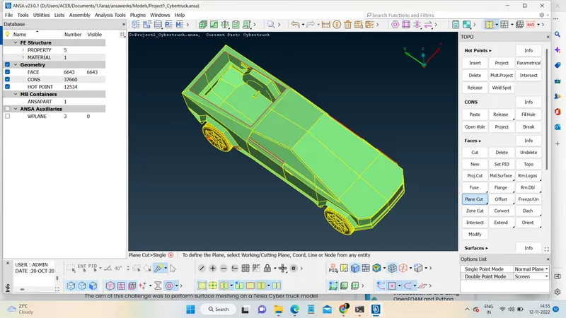
Delete one side of the model
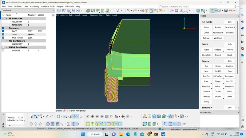
Fill the holes, apply new faces, remove topological errors, remove penetration errors where ever needed
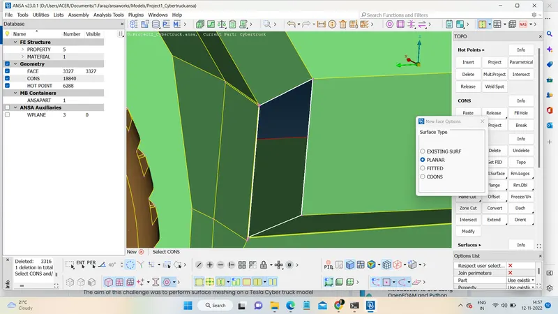
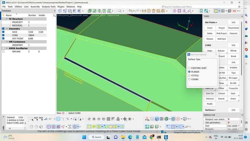
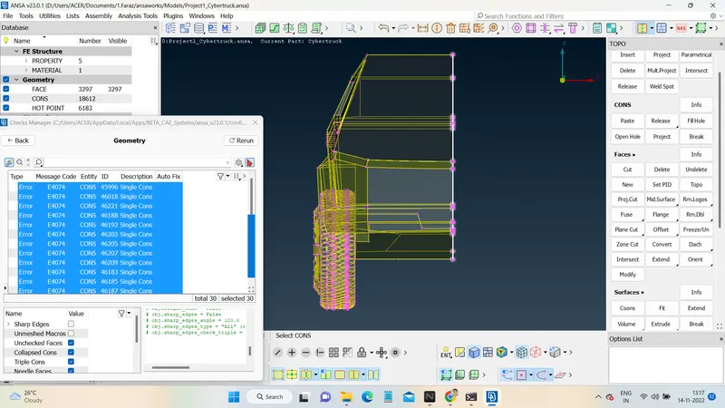
After clearing all the errors check for remaining errors in Checks > Geometry and then execute if any any clear them as well (Single cons at symmetry are not errors as we will do the symmetry later and join both side's respective single cons into double cons)
PID Assignment:
Create new PIDs by nameing appropriate parts name
Then assign the parts by selecting in model
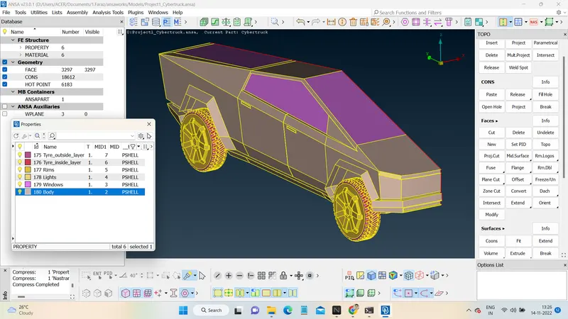
Here, I've created six PIDs.
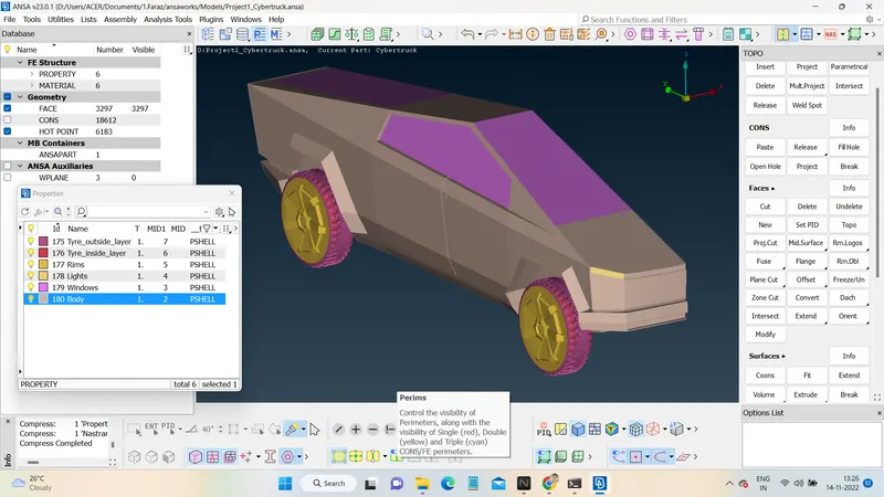
Surface Meshing:
While creating surface mesh for any model, part or PID there are mainly 4 parameters we usually give
- Mesh parameters
- Quality Criteria
- Perimeters in Lenght <Perimeters
- Macrons in Lenght <Perimeters
The Mesh parameters and Quality Criteria for the different PIDs of a model are as follow:
| Target length (mm) |
Minimum length (mm) |
Maximum length (mm) | |
| Windows | 5 | 3 | 7 |
| Lights | 5 | 3 | 7 |
| Rims | 4 | 2 | 6 |
| Tyre_inside_layer | 1 | 0.2 | 2 |
| Tyre_outside_layer | 2 | 0.2 | 3 |
| Body | 3 | 1 | 5 |
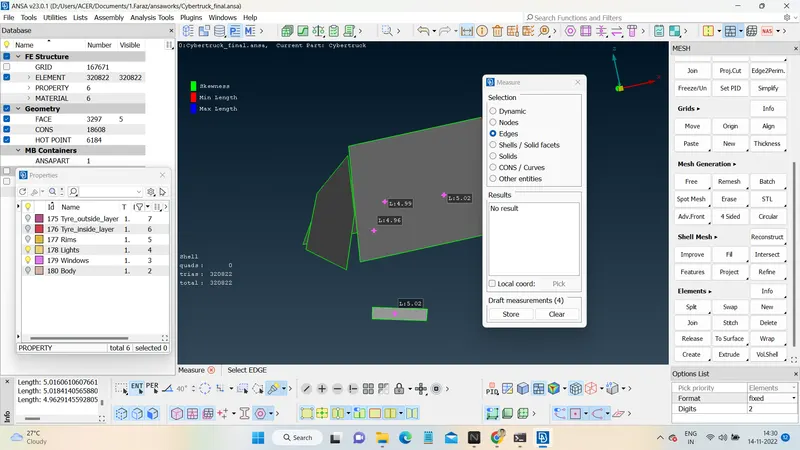
1. Meshing Windows and Lights
Target length is 5mm and range(Quality Criteria - min to max) is 3mm to 7mm
Perimeters > Length > Perimeters 5mm
Perimeters > Length > Macrons 5mm
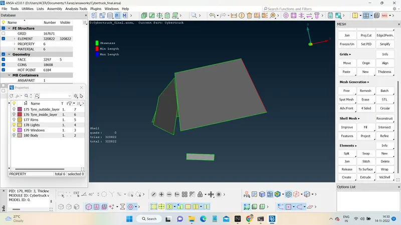
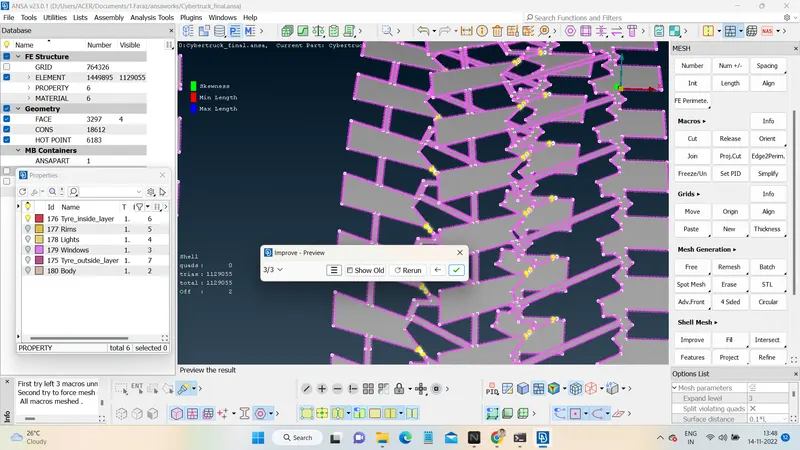
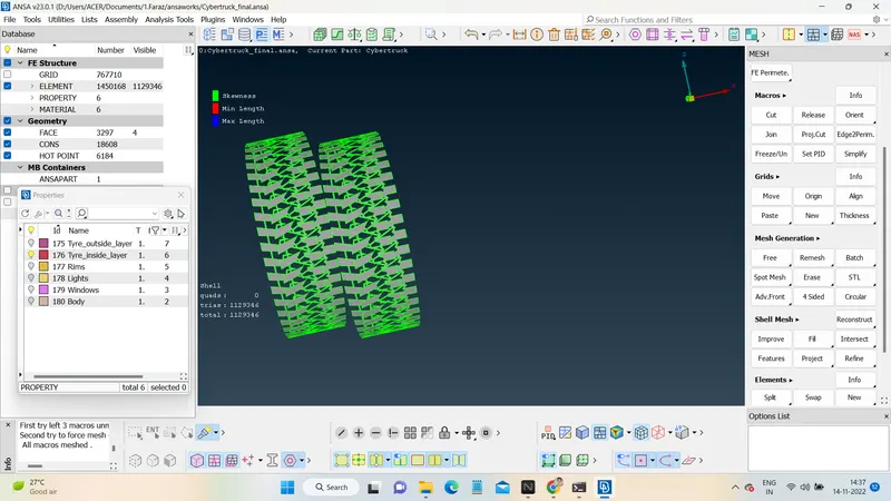
2. Meshing Tyre_inside_layer
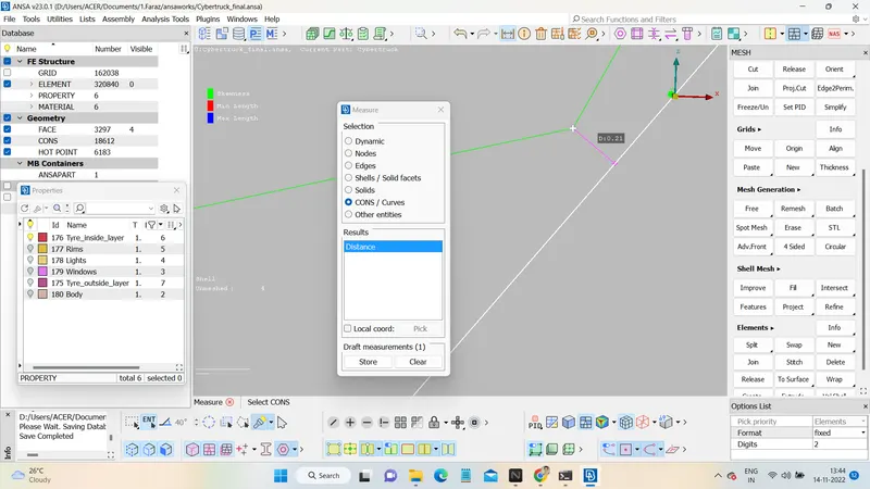
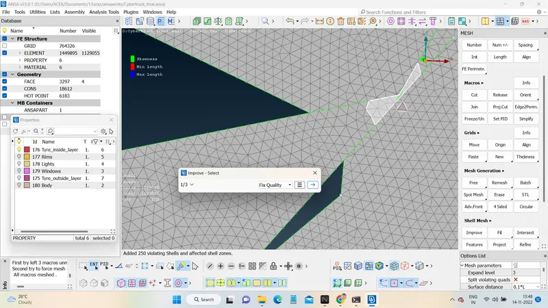
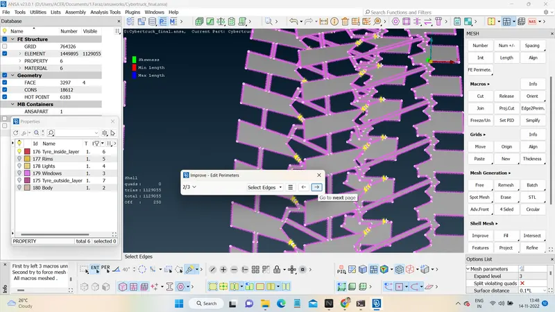
Target length is 1mm and range is 0.2mm to 2mm
Perimeters > Length > Perimeters 1mm
Perimeters > Length > Macrons 1mm
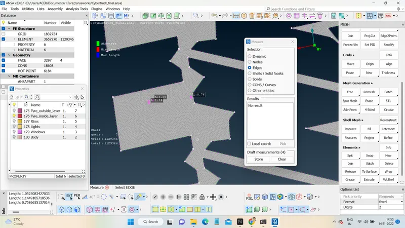
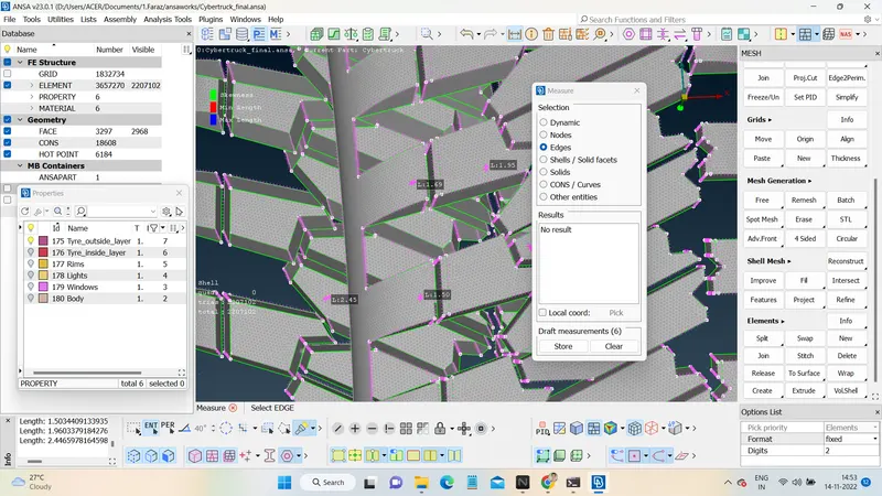
The minimum distance in this geometry is 0.21mm which can not be changed hence out minimum length is 0.2mm
3. Meshing Tyre_outside_layer
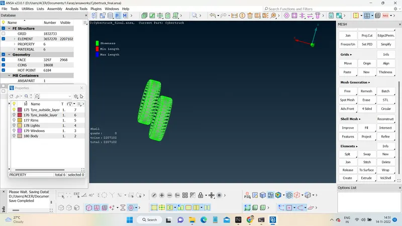
Target length is 2mm and range is 0.2mm to 3mm.
Perimeters are not given, because the geometry is too complex and selecting each cons between outside and inside layers can take lot of time so i gave Length > Perimeter of 2 mm to the whole geometry at the beggining itself.
So the default peremeter is 2mm and the perimeter of cons in contact with inside layer is 1mm so donot change those.
The minimum distance in this geometry is 0.2 mm because the inside layer with 0.21 mm edges could be in contact.
4. Meshing Rims
Target length is 4mm and range is 2mm to 6mm
Perimeters > Length > Perimeters 4mm
Perimeters > Length > Macrons 4mm
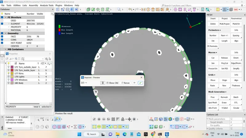
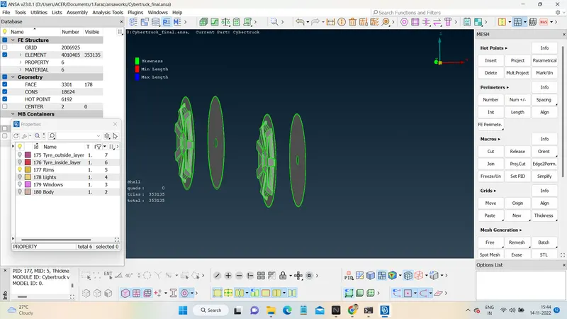
While giving the perimeters for cons in this PDI Deselect the Edges in contact with Tyre_outside_surface because it already has been divided or given perimeters of 2mm while meshing the same PDI.
And also give a transition zone by adding cons (Circular cons inside the cons that are in contact with Tyre_outside_srface) so that the remaing surface has only 4mm cells not 2mm
5. Meshing Body
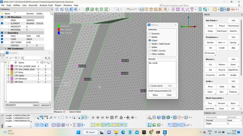
Target length is 3mm and range is 1mm to 5mm
Perimeters > Length > Perimeters 3mm
Perimeters > Length > Macrons 3mm
While giving the perimeters for cons in this PDI Deselect the Edges in contact with any other PIDs i.e., Windows, Lights and Rims
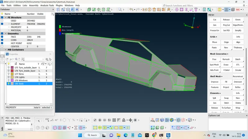
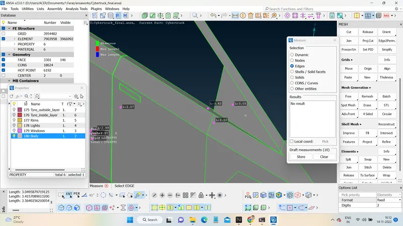
Whole geometry after surface Meshing
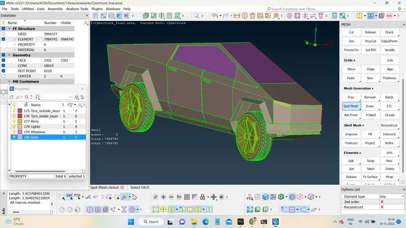
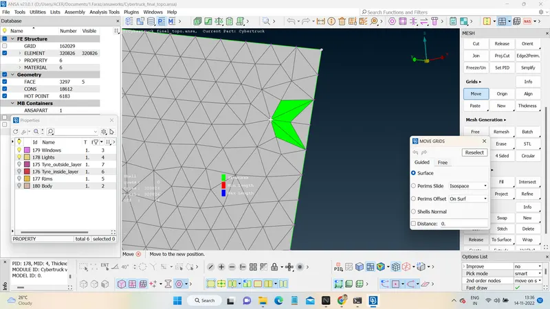
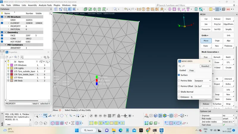
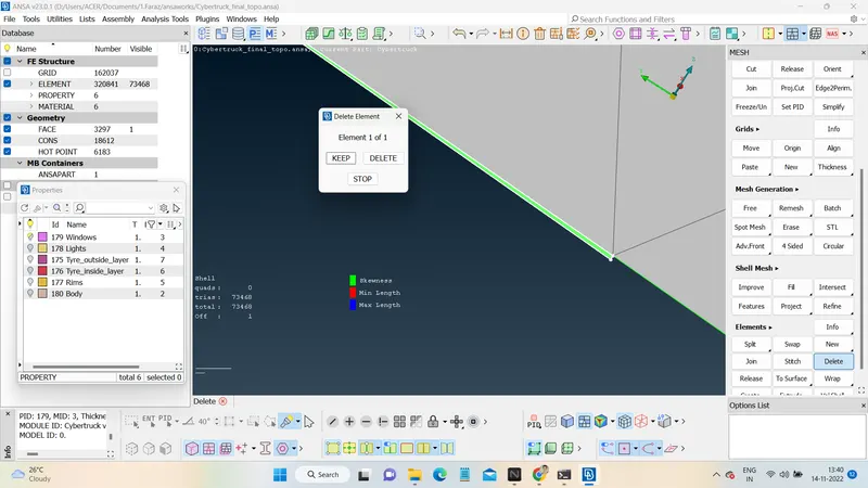
How to clear the Off elements
There many options available that you can use for automatic correction like
- Improve , Reconstruct, Reshape, Fix quality, Smooth etc.
- Also you can select area to be used like violating, selected or visible
- Also you can act on it with either edges or nodes
- It helps in a large numer of off elements
There are also options available for correcting the off elements manually
- Move, split, join, delete and ,many more
- These are used if aoutomatic correction is not able do anything for these elements
- Generally they are only small amount of elements
- In this model I mainly used Move > Grid option and Split > Elements and also sometimes Delete > Elements
Symmetry:
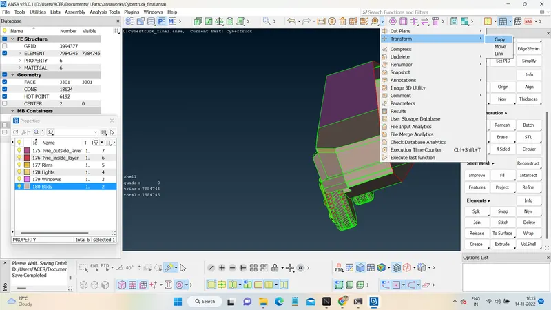
For creating the full cyber truck use symmetry and copy the whole model
Go to Transform > Copy > Symmetry > 3 point plane then select the components to be copied in this case the whole model.
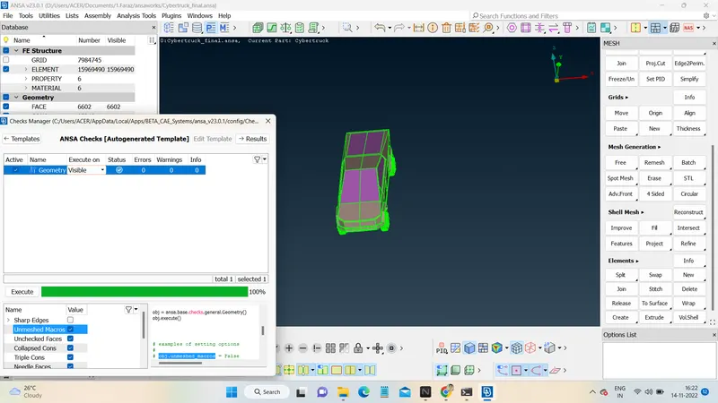
Check for errors, sometimes the cons do not attach, in such cases we have to do clean manually
Cyber Truck Surface Meshed
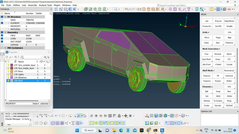
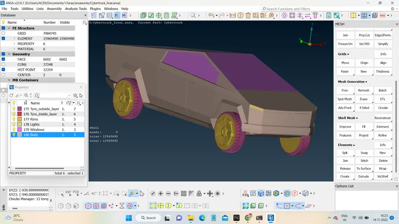
Some Meshed surfaces with Different Mesh length
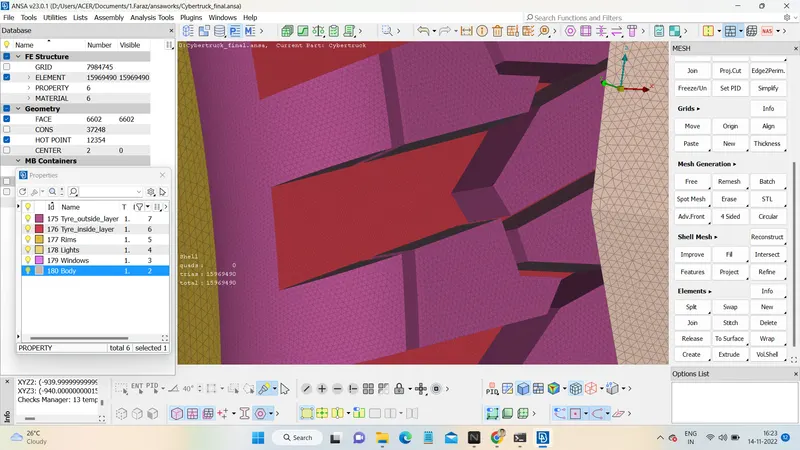
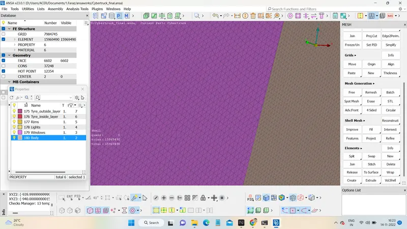
Wind Tunnel:
The approximate length of truck is 6000mm, width and hight is 2000mm. For creating tunnel Create a Reference point at bottom then from it create points 36000mm front, 24000mm back and 6000mm top of the truck. From these points create lines and then surfaces.
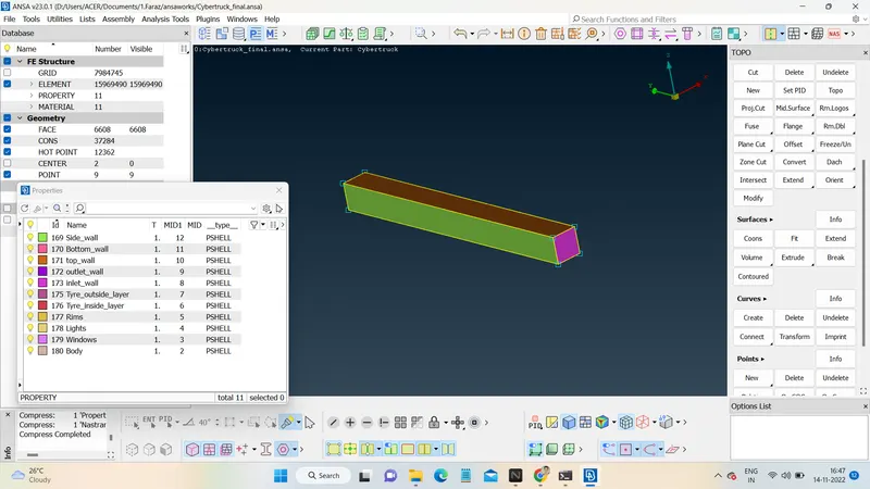
Create new PIDs and assign the walls of tunnel with appropriate PIDs i.e., Top, Bottom, Side Wall, Inlet and Outlet.
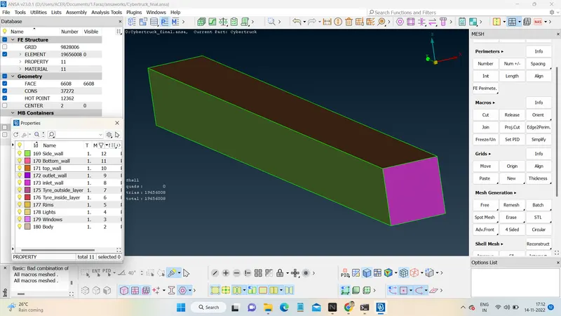
Then for surface meshing of Tunnle
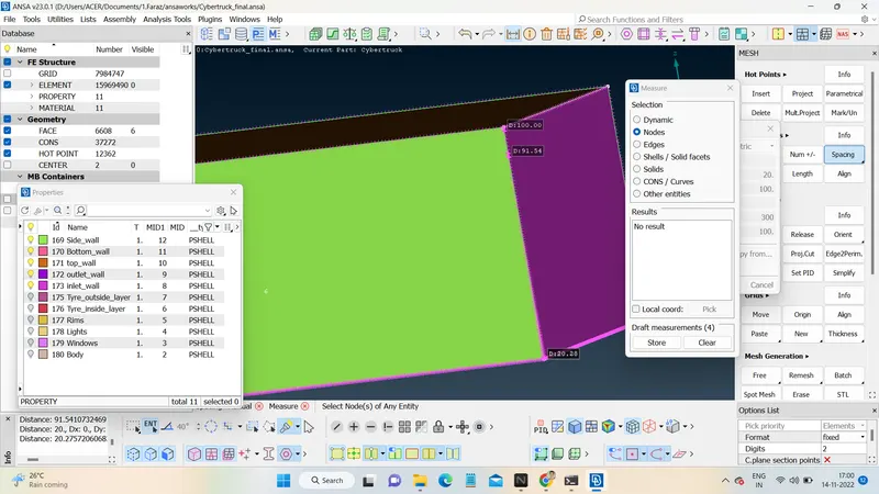
Top wall :- Taget mesh= 100mm Range= 80mm to 120mm
Bottom wall :- Taget mesh= 20mm Range= 15mm to 25mm
For remaining walls use Spacing because we need the element size to go from 20mm to 100 mm bottom to top
Perimeters > Spacing Give Dstart= 20 and Dlimit= 100
Volume Meshing:
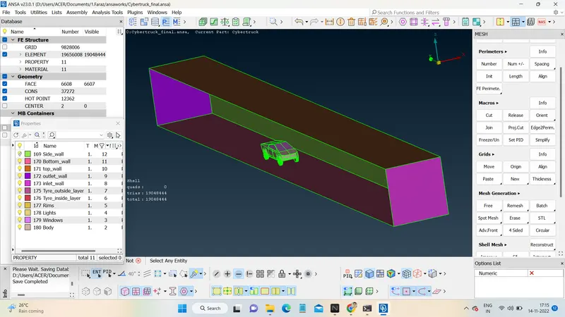
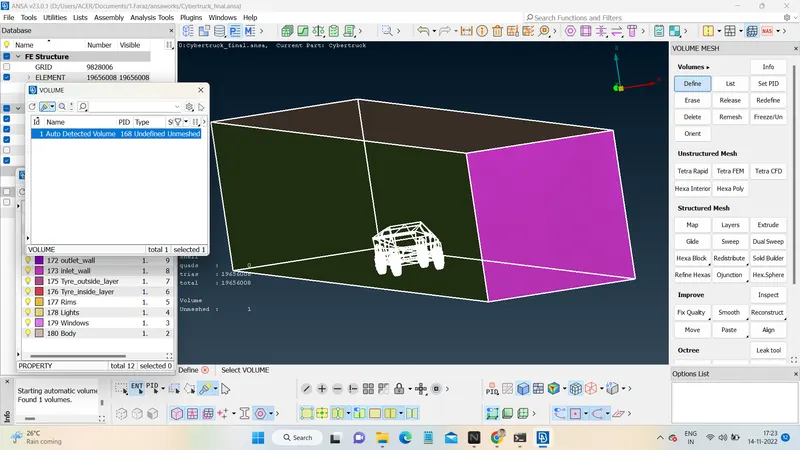
Extract the volume btween the Car and the tunnel and delete any other.
Volume mesh > Define volume > whole db
The volume is extracted and ready to be meshed but it is very file and it will a lot of time and a powerfull processor. So we will leave it at that
Link for the Model is given below: