Week 3 Challenge : CFD meshing on Turbocharger
Aim:
Performing CFD meshing on Turbocharger using ANSA
Objective:
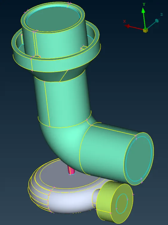
For the given model, check for the geometrical errors to make appropriate volumes. Create and assign PIDs as shown in the video. Perform surface mesh with the given target lengths as per PIDs.
- Blade stage-1 = 1 mm
- Blade stage-2 = 1 mm
- Impeller = 2 mm
- Shaft rotor = 1 mm
- Turbo casing = 5 mm
- Compressor casing = 5 mm
- Inlet casing cover = 5 mm
Perform Volumetric mesh for the required volumes.
PROCEDURE:
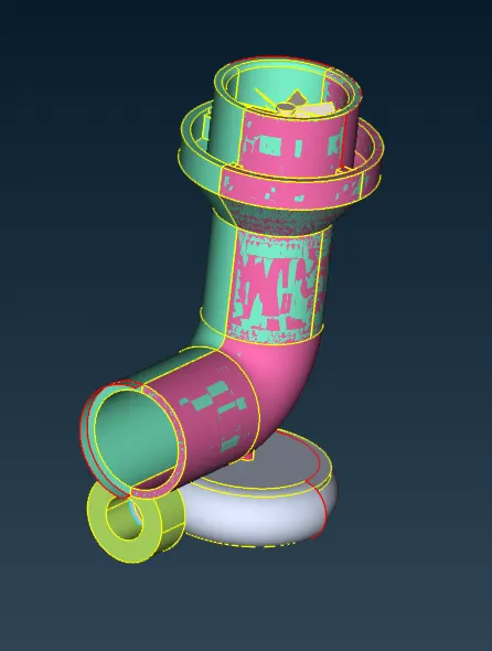
1. Patching the missed surfaces:
- Import the geometry model from the source folder.
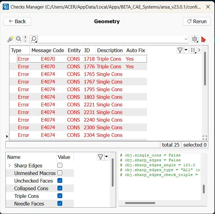
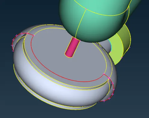
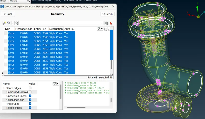
- The geometry file contains lot of ir-regularities, discontnuities, so we need to patch all the missing and open surfaces in the geometry.
- This can be done by the following procedure;
TOPO → faces → new → select any method → select the cons (entity or PID) → middle click.
2. Removing overlapped surfaces:
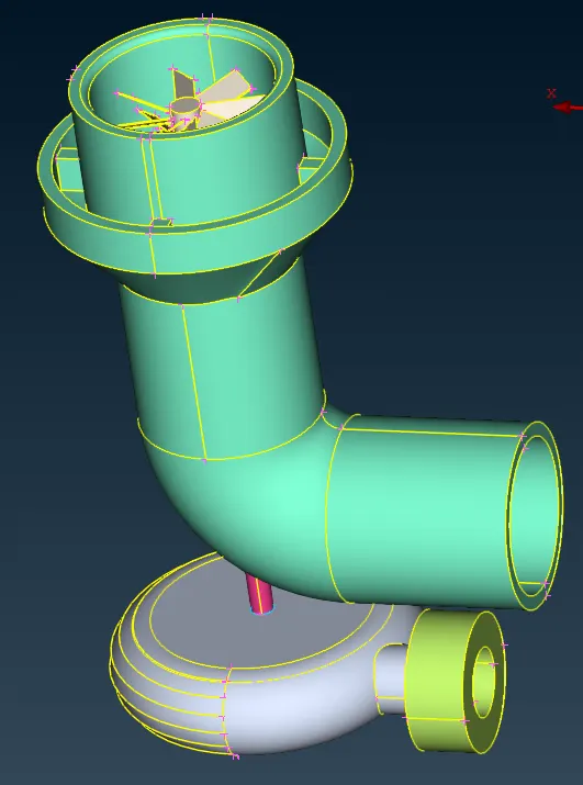
- At some areas of the geometry, we need to clear the overlapped surfaces.
- This can be done by following procedure;
TOPO → delete → select the surface to be deleted (entity or PID) → middle click.
- Sometimes we need to project the cons to make the single cons into triple cons.
- This can be done by the following procedure;
TOPO → cons → project → select the cons → middle click → select the face where the cons has to be projected → middle click.
3. PID assigning:
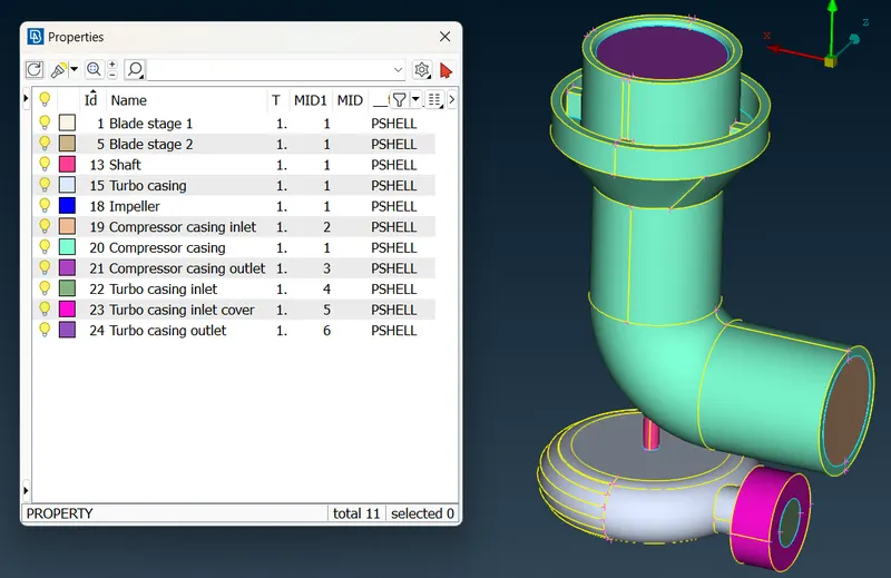
- Now we need to create PID (Property ID) for all the surfaces like inlet, outlet, turbo casing, compressor casing, blades, impeller,etc,.
- This can be done by the following procedure;
Properties → right click → new → PSHELL → PSHELL → box pops-up → name has to be given.
- Similarly we need to create as many as required.
- Now we need to assign the created PID 's to the respective surfaces required.
- This can be done by the following procedure;
Properties → right click on the PID → apply → select surface of the geometry → middle click.
- Similarly we need to do for all the required surfaces.
4. Surface mesh process:
- Now we need to mesh the geometry.
- Meshing the geometry part by part individually and each part or component is given different element length.
- Meshing can be done by following procedure;
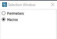
Meshing module → select the Length under Perimeters → give length for both Perimeter and in Macros.
Mesh parameters → give the target length, min and max length in that dialog box.
Quality criteria → give the target length, min and max length in that dialog box.

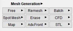
Mesh generation → spot mesh → select the geometry to be meshed.
5. Volume mesh process:
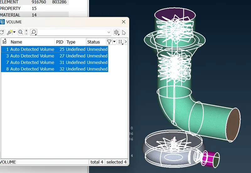
- Now we need to move to volume mesh.
Volume → define → work on → whole db.
- Now we need to drop volume mesh to the geometry.
- This can be done by following procedure:
Volume → list → here we need to select the component to do volume mesh → right click → remesh → fluent method. (also delete the thickness volume which is not needed)
Resuts:
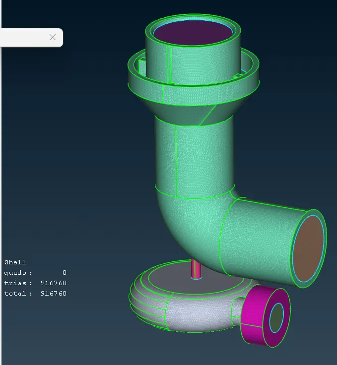
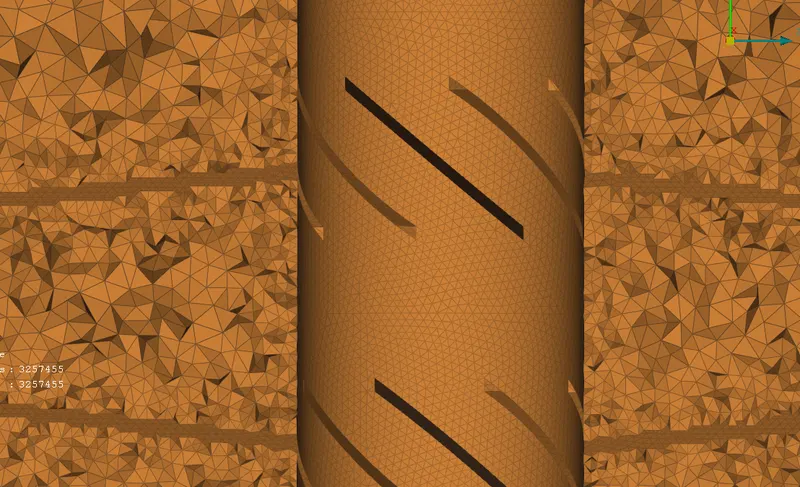
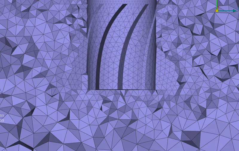
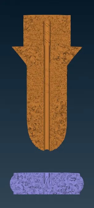
Surface Mesh
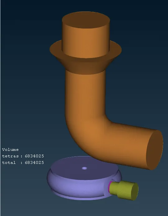
Volume Mesh
Total Mesh
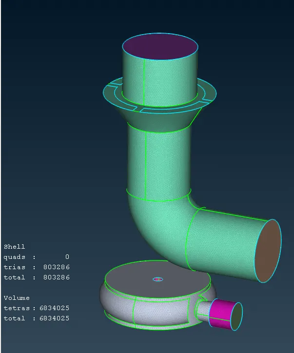
Cross Sectional Veiw
Conclusion:
- The objective of performing a Topology Cleanup and mesh the geometry of a Turbocharger with different mesh length elements assigned to their respective PID region.
- Variation in the mesh lengths has been performed and also the volumetric Mesh for the same has been performed.
- The output representation is as shown below and the supporting Model File has been linked below.
Click here: https://drive.google.com/file/d/1-5t9XdYZFj3iWMSMHK_8OTw2s_mU5sKt/view?usp=share_link