Project 1
Motor power (Po) = 5 hp = 3.75 KW
Motor required voltage (V) = 230 V
Motor operating frequency (F) = 60 Hz
Stator poles (p) = 4
Stator resistance (`r_s`) = `0.513 Omega`
Rotor resistance (`r_f`) = `0.408 Omega`
Motor inertia (J) = 0.1 `Kg-m^2`
Stator inductance (`L_1s`) = 2.52 mH
Rotor inductance (`L_1r`) = 2.52 mH
Magnetizing inductance (Lm) = 84.7 mH
Procedure:
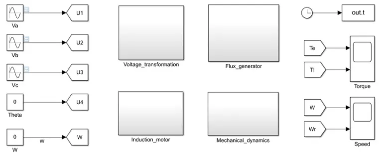
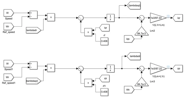
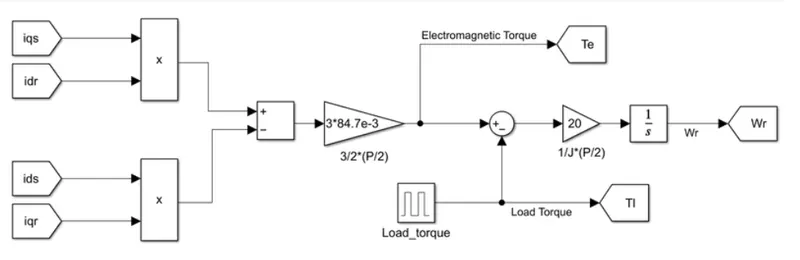
For the given parameters, the following figures show the designed model of a 5 hp squirrel cage induction motor
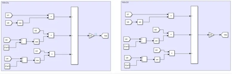
Voltage transformation subsystem:
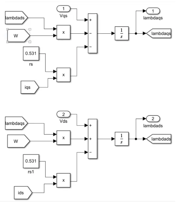
Flux generator subsystem:
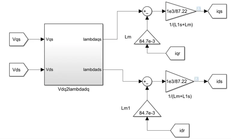
Induction motor subsystem:
Mechanical dynamics subsystem:
Load torque:

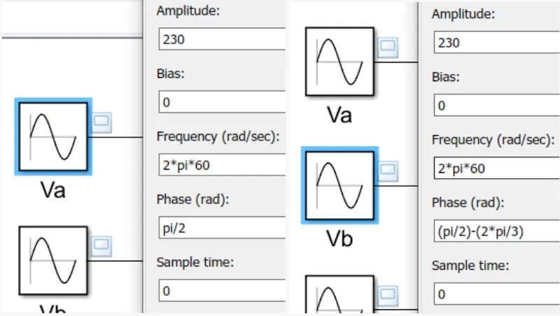
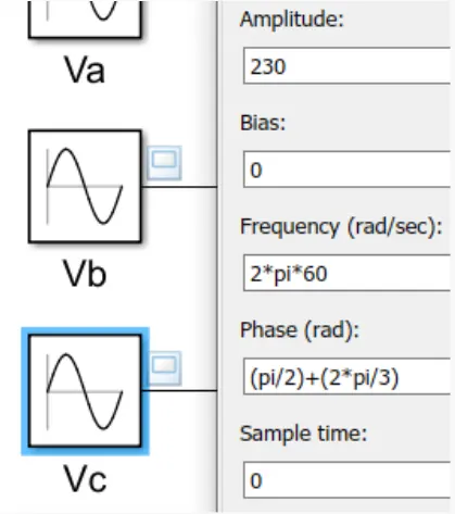
3-phase balanced supply:
- Simulating the start-up behavior of the induction motor represented in the stationary d-q reference frame:
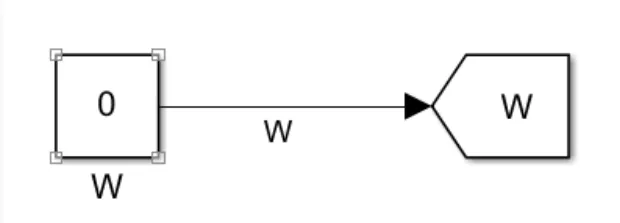
When initial speed =0
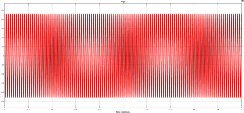
`V_(qs)(t)`:
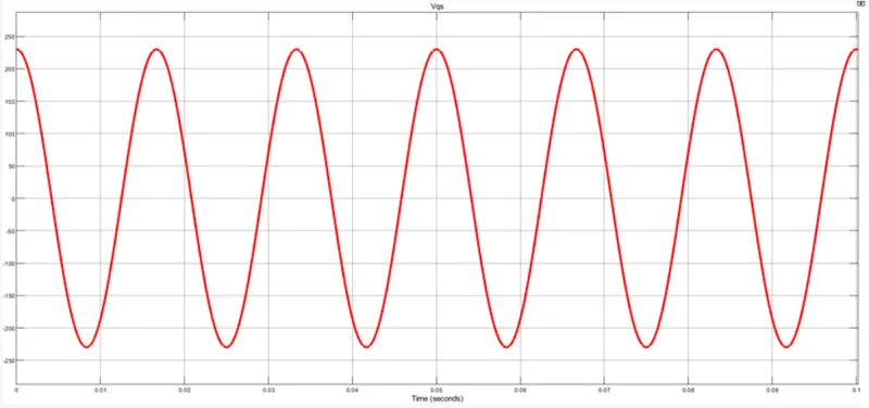
Zoomed-in:
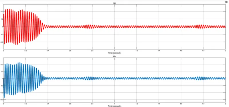
`i_(qs)(t)` and `i_(ds)(t)`:
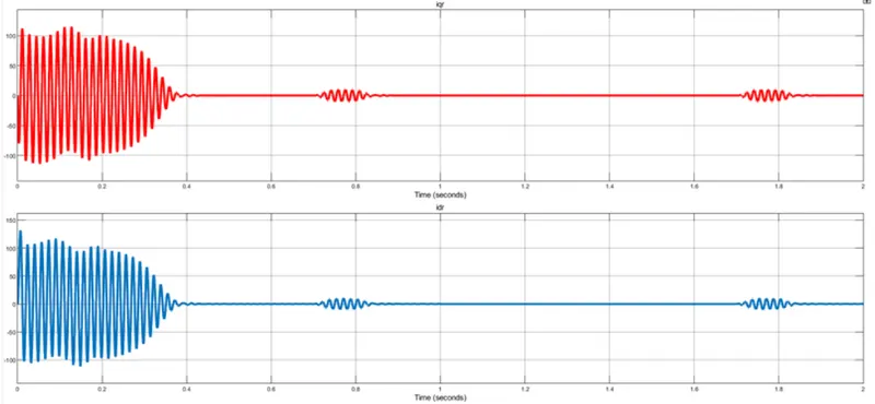
`i_(qr)(t)` and `i_(dr)(t)`:
Electromagnetic torque and Load torque:
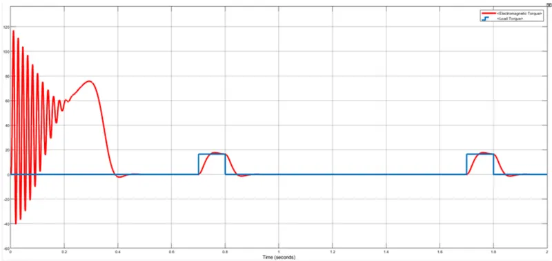
The Electromagnetic torque is following the Load torque when required.
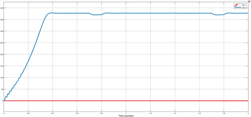
Initial speed and Rotor speed:
- Simulating the start-up behavior of the induction motor represented in the synchronous reference frame:
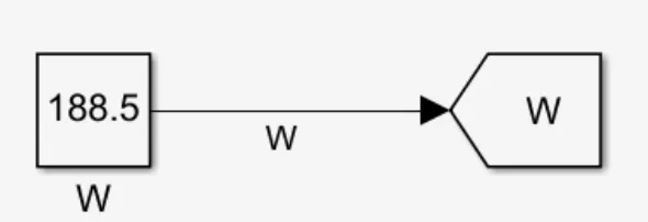
When Synchronous speed Ns = Rotor speed N
We know, Ns = `(120*F)/p`
`therefore N = N_s = (120*60)/4 = 1800` rpm
Therefore, speed in rad/sed (`omega`) = `(2pi*N)/60`
`therefore omega = (2pi*1800)/60 = 188.5` rad/sed
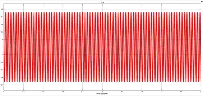
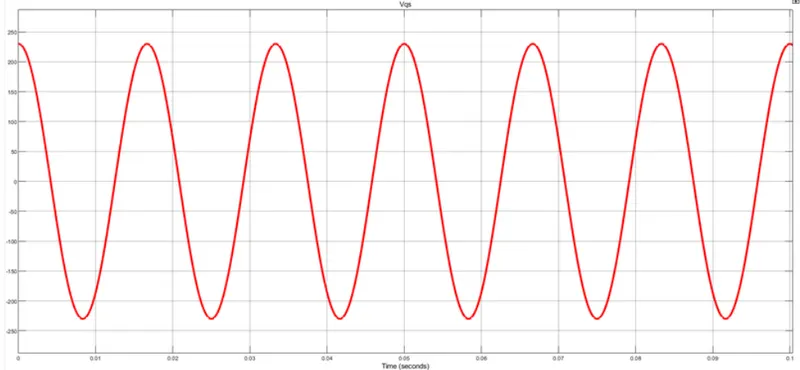
`V_(qs)^e(t)`:
Zoomed-in:
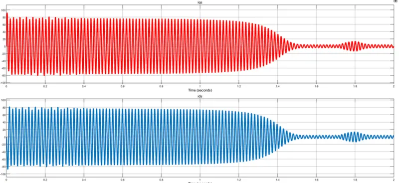
`i_(qs)^e(t)`:
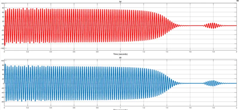
`i_(qr)^e(t)`:
Electromagnetic torque and Load torque:
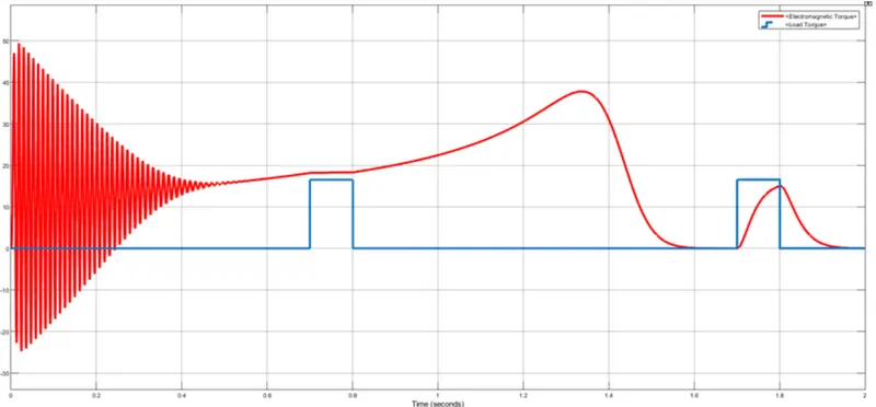
When the synchronous speed and rotor speed are matched, the electromagnetic torque developed is higher than the load torque.
Initial speed and Rotor speed:
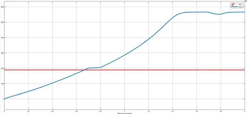
- Simulating the start-up behavior of the induction motor represented in the rotor reference frame:
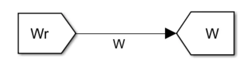
When Initial speed (`omega`) = Rotor speed (`omega_r`)
`V_(qs)^r(t)`:
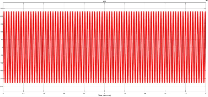
Zoomed-in:
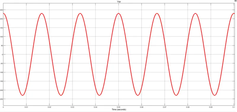
`i_(qs)^r(t)`:
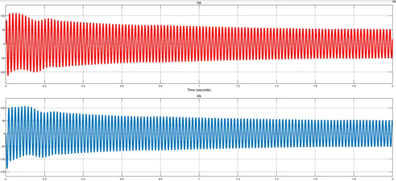
`i_(qr)^r(t)`:
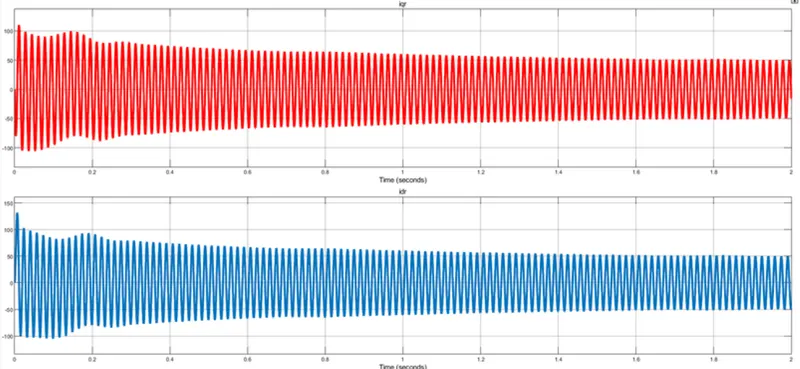
Electromagnetic torque and Load torque:
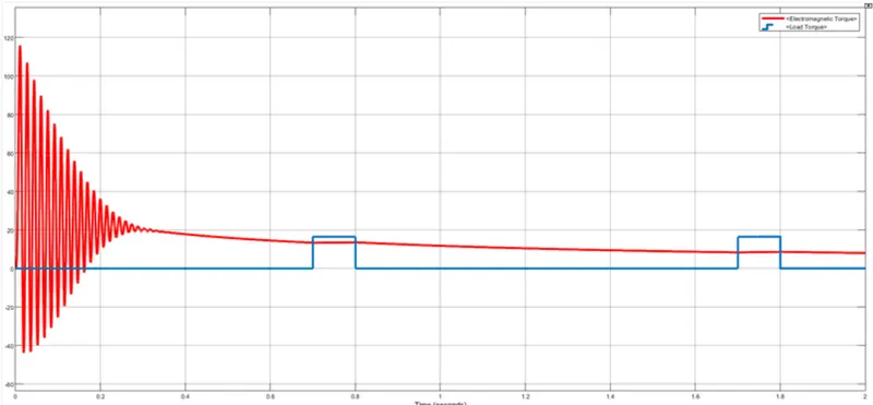
When the initial and rotor speeds are matched, the electromagnetic torque developed is less than the load torque.
Initial speed and Rotor speed:
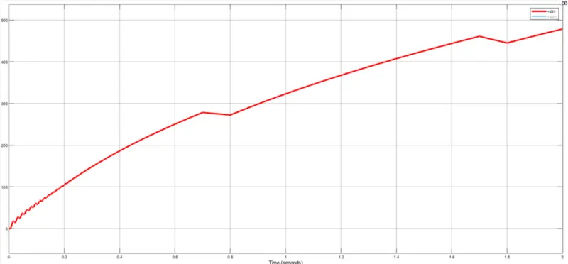
- Simulating the start-up behavior of the induction motor represented in the rotor flux reference frame:
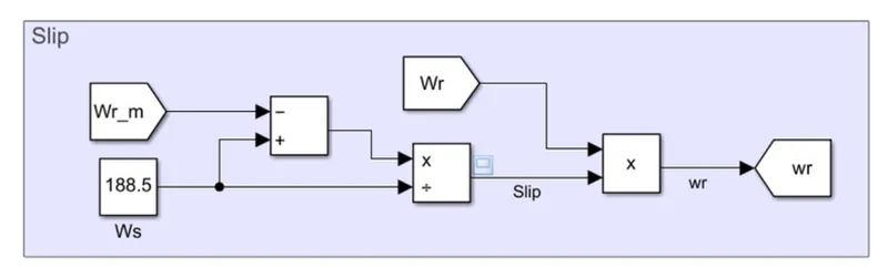
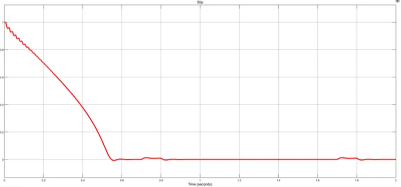
Slip = `(omega_s-omega)/omega_s`
New rotor speed = Slip x Calculated rotor speed
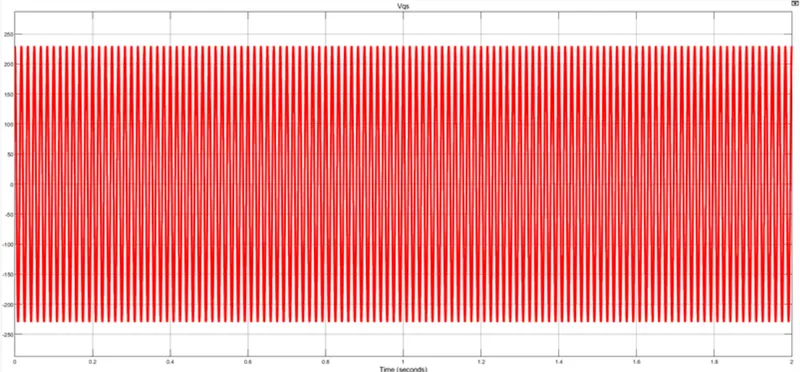
`V_(qs)^(rf)(t)`:
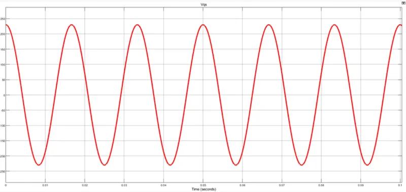
Zoomed-in:
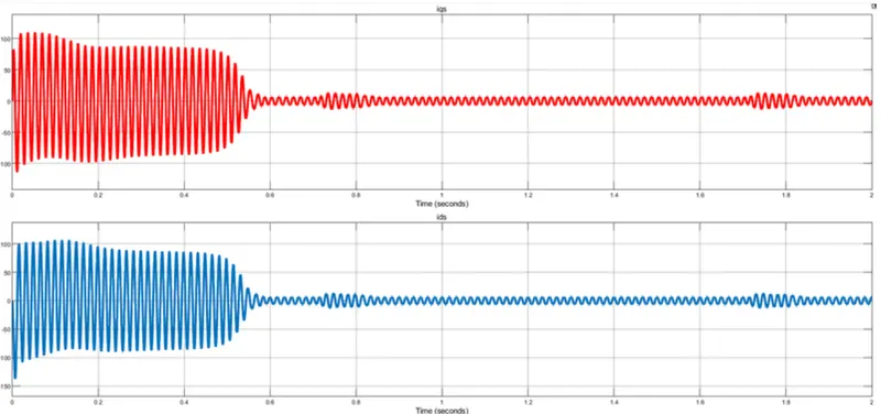
`i_(qs)^(rf)(t)`:
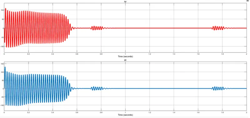
`i_(qr)^(rf)(t)`:
Electromagnetic torque and Load torque:
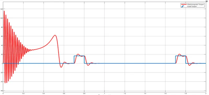
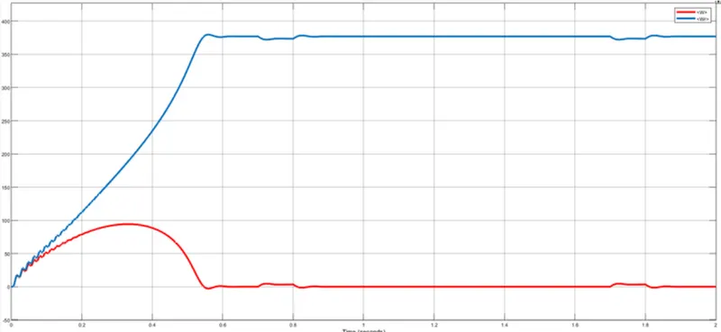
When the slip is added to the initial speed, the electromagnetic torque is developed when the load torque is required.
Initial speed and Rotor speed:
Conclusion:
Thus, the design and simulation of the starting behavior of a 5 hp 3-phase Induction motor has been performed satisfactorily.