MATHEMATICAL_MODEL_INDUCTION_MOTOR
Question:-
Simulate the starting behaviour of a 5 horsepower(3.75kW), 3-phase 3-wire, 230V, 60Hz, 4-pole squirrel cage induction machine with parameters:-
- rs=0.531Ω,
- Lls=Llr=2.52mH
- rf=0.408Ω">rf=0.408Ω,
- Lm=84.7mH
- J=0.1kgm2
The machine is suddenly connected to a balanced three-phase 230V rms sinusoidal supply voltage at frequency 60Hz. After reaching rated speed the motor is loaded to 0.83 times rated torque at 0.7secs. The load is removed after 0.1sec.
Aim:-
The main aim is Simulate the starting behaviour of a 5 horsepower(3.75kW), 3-phase 3-wire, 230V, 60Hz, 4-pole squirrel cage induction machine with given parameters.
Given data:-
- rs=0.531Ω,
- Lls=Llr=2.52mH
- rf=0.408Ω">rf=0.408Ω,
- Lm=84.7mH
- J=0.1kgm2
ANSWER:-
DYNAMIC MODEL OF INDUCTION MOTOR:-
The dynamic simulation is one of the most important processes in the validation of the motor drive system's design
process, as it eliminates design errors and the resultant problems in prototype fabrication and testing. Fundamental
transformation equations can be used to derive the dynamic model of the induction motor in direct, quadrature, and
zero-sequence axes.
The dynamic analysis of symmetrical induction machines in any reference frame has been widely
used as a basic simulation approach from which any mode of operation may be created. When modelling the induction
machine utilising the dq0 axis transformation, Matlab/Simulink has an advantage over other machine simulators.
Because modelling these equations is often regarded as challenging, they are presented in this study in their simplified
version.
The transformations are based on simple trigonometric relationships acquired as projections on a set of axes at
various stages. Transient responses, small-signal equations, and an induction motor transfer function are all obtained
using the dynamic model. To better understand the behaviour of induction motors in both transient and steady-state,
dynamic models (mathematical models) are used.
Equivalent circuit of induction machine:-
The voltage and torque equations that explain an induction motor's dynamic behaviour are time-varying. It has been
successfully utilised to solve such differential equations, however, it may be complicated. By removing all time-varying
inductances owing to electric circuits in relative motion from the machine's voltage calculations, a change of variables
can be employed to simplify these equations.
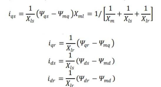
An Induction motor's dq0 equivalent circuit is shown in the diagram above. The circuit consists of several time varyinginductances that must be simulated in order to analyse the 3-phase Induction motor's dynamic performance.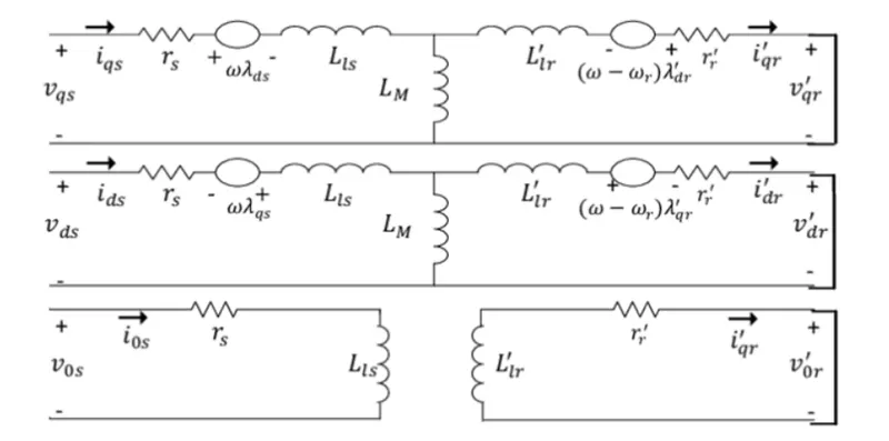
The three-phase stator voltages of an induction machine can be represented as
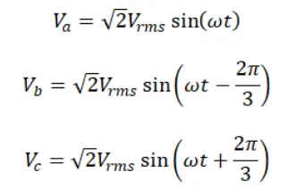 -------------------------------------------(1)
SIMULINK MODEL:-
For creating the Simulink model we have to use the Following Blocks :-
Sine wave
fcn
Constant
product
add
Integrator
goto
From
Gain
Pulse generator
Scope
The Total Simulink Model :-
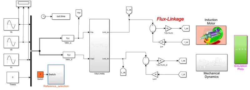
The Dynamic Model of Induction Motor Consists of following Subsystem Blocks.
- Threee phase voltage
- abc to dq transformation
- Flux Linkage
- Induction Motor
- mechanical Dynamics.
- Simulatio results
Three phase Voltage :-
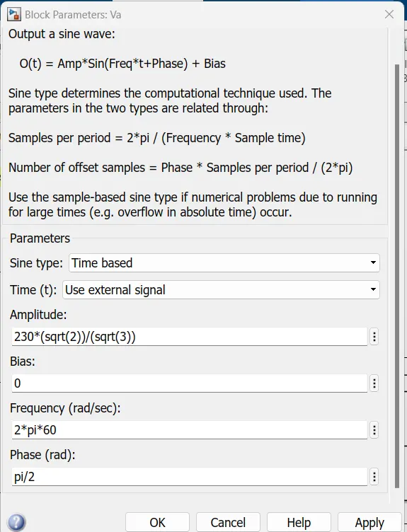
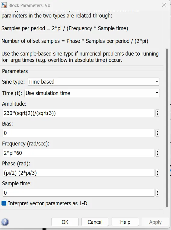
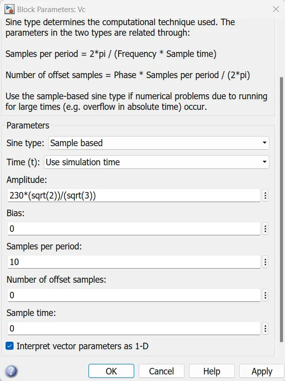
This block is created by using the "Sine wave Block"
With following parameter values
The parameter values for phase a(va) are as follows.
The parameter values for phase b (vb) are as follows.
The parameter values for phase c (vc) are as follows.
The relatin ship betwwen abc and αß is as follows.
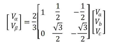 ----------------------------------------(2)
From this we can get the dq voltages as follows.
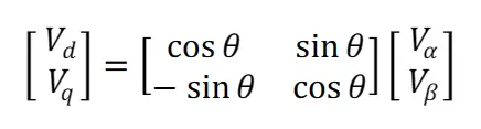 --------------------------------------(3)
abc to dq Transformation:-
for transformation of abc to dq we are used for this model is "Fcn" block with following parameter values.
The function which is used in this abc to q is from the equtation (3) implements as follows.
(2/3)*(u(1)*cos(u(4)))+u(2)*cos(u(4)-(2*pi/3))+u(3)*cos(u(4)+(2*pi/3))
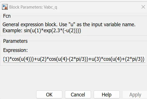
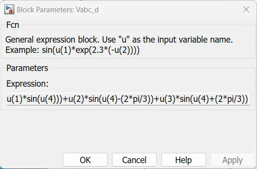
for transformation of abc to dq we are used for this model is "Fcn" block with following parameter values.
The function which is used in this abc to d is is from the equtation (3) implements as follows.
(2/3)*(u(1)*sin(u(4)))+u(2)*sin(u(4)-(2*pi/3))+u(3)*sin(u(4)+(2*pi/3))
dq to lamda transformations:-
For Lamda-qs:-
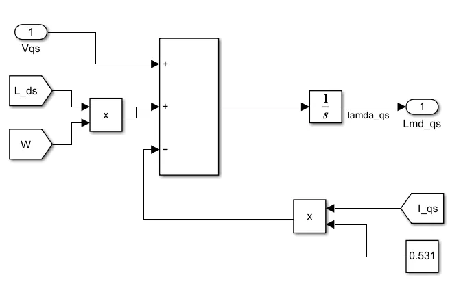
>>For Creating the dq to Lamd-d,q we are using the above subsytem.
>>it take the three inputs as adding with help of add block.
>>The output product of those three inputs can be integrated to get lamda-q
in this same process we have to determine the Lamda-d as follows.
For Lamda-ds:-
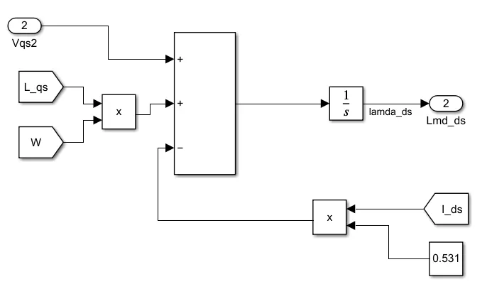
>>For Creating the dq to Lamd-d,q we are using the above subsytem.
>>it take the three inputs as adding with help of add block.
>>The output product of those three inputs can be integrated to get lamda-d
Flux Linkage:-
The Flux linkgae is implemented by using the following equtation

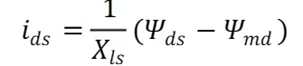
where ,
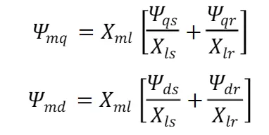
but,
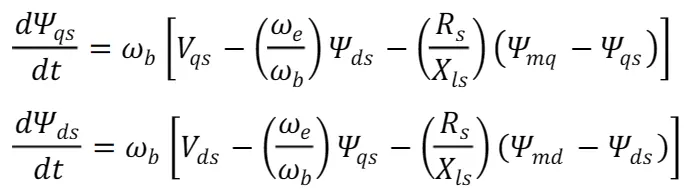
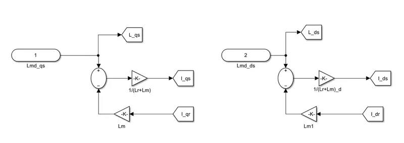
>>From the Flux linkage we have to find the Stator Current for the both qand d axis.
>>This will determined by using the LAmda q and d values
>>The simulink for the determinatio of Stator d and q curents is above menctioned.
Induction Motor:-
Simulink Model:-(INDUCTION-MOTOR)
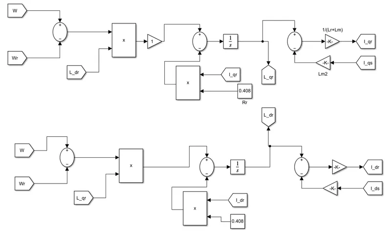
>>In this model we have to determine the rotor currents with help of Error signal is created between the "Angular and relative speed and fed tothe in put of produc and Lamda q and d axis values are product with that error signal
>>This signal is integrated and multiplied with help of lm and ls values using the gain block.
>>This total simulink for this model is menctioned above block.
Mechanical Dynamics :-
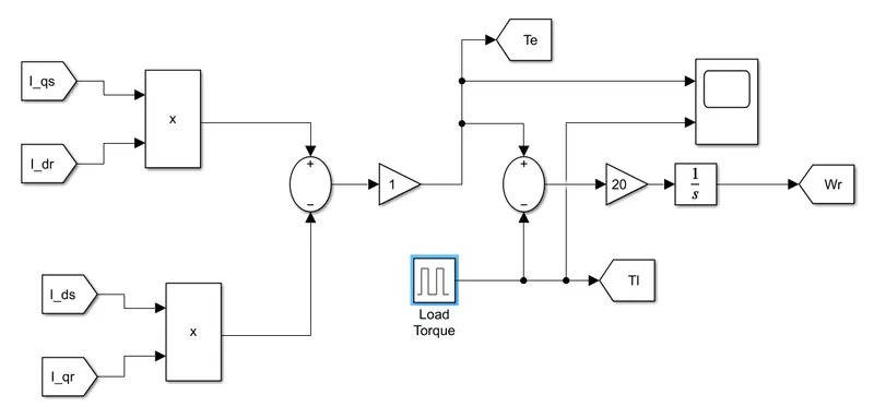
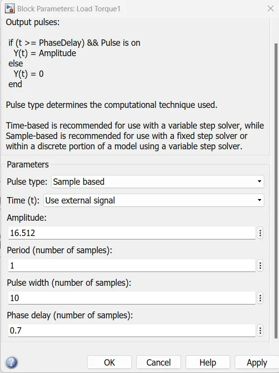
Here the load Torque s created by using the Pulse generatorBlock is menctioned in above simulink model.
parameter values:-(load Torques)
>>Mechanical dynamics is for determineing the relaive speed .
>>this can be determined with help of Load Torque and Electromagnetic Torque as menctione above simulink block.
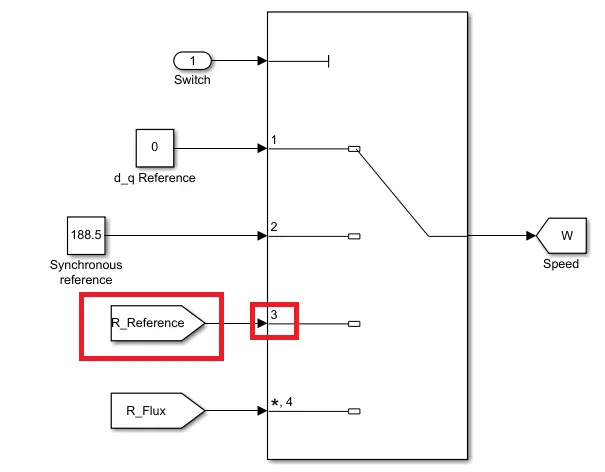
The Speed is sending in 4Different Ways Those are created by using the Simulink as follows.
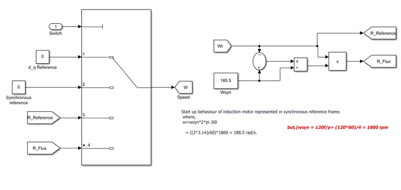
The Reference speed is basically depends on the following criteria as per the required in question.
1)d-q reference
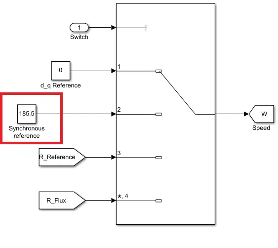
2)Synchronous REference
3)rotor reference frame
4)rotor flux reference frame
>>the selector switch is for select the which input is fedd to is given to the output .using the Constant block.
Simulink Results :-
Input voltages :-
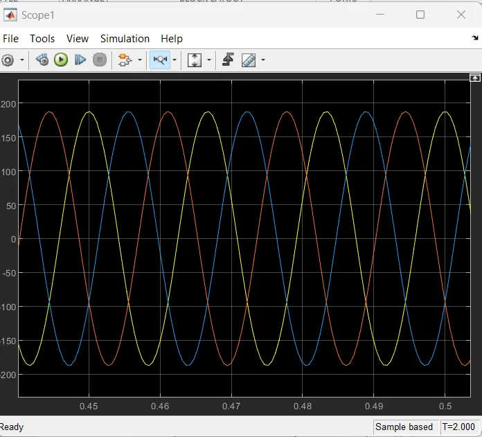
>>The Three phase voltage source with each pahse difference of
- a phase -0°
- b phase-(-2π/3)°
- c phase-(2π/3)°
>>this variation can be observed in above Graphical representation.
a) Simulate the start-up behaviour of the induction motor represented in the stationary d-q reference frame. Provide simulation plots of vqs(t),iqs(t),ids(t),iqr(t),idr(t),Te(t),Tl(t)andωr(t).
For getting the stationary d-q reference frame(w=0)
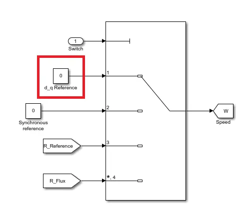
Simulation Results:-
For Vqs:-
>>from the above graph we can get the graphical representation of duadrature axis stator voltage.
>>this "vqs" having the following statistics.
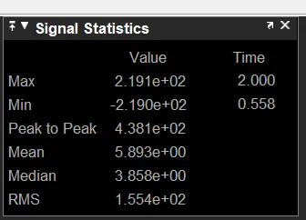
>>The Minimum voltage value is -2.19e2 V at 0.558 sec of time
>>The maximum Voltage value is 2.191e2 at 2.00sec
FOR Ids and Iqs:-
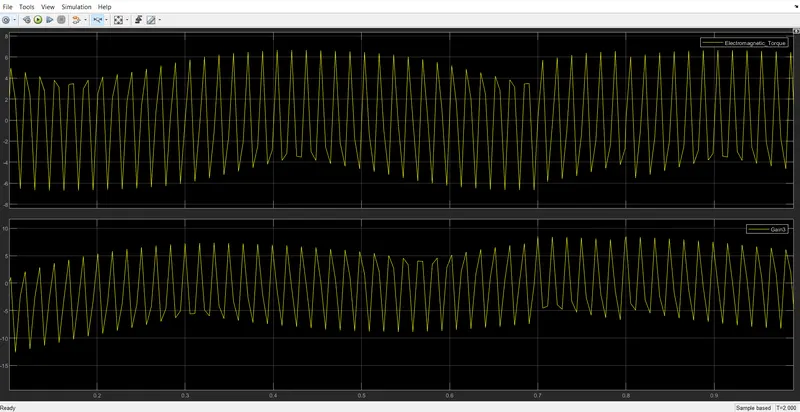
>>from the above graph we can observe that the Top plot is for stator Current in qudrature axis and
>>Below plot is for the stator Current in Direct axis.
>>the both axis consists the follownig Statistics.
FOR -Iqs
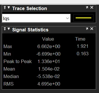
>>the minimum current is -6.699 at 0.163 sec
>>the maximum current is 6.662 at 1.921 sec
FOr Ids:-
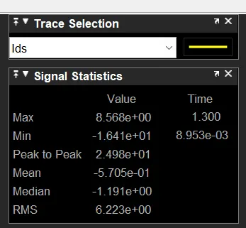
>>the minimum current is -1.699 at 8.953e-3 sec
>>the maximum current is 8.568 at 1.300 sec
FOR Idr and Iqr:-
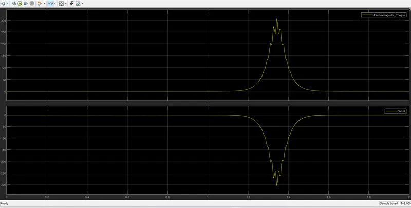
>>from the above graph we can observe that the Top plot is for Rotor Current in qudrature axis and
>>Below plot is for the Rotor Current in Direct axis.
>>the both axis consists the follownig Statistics.
For Id_r;-
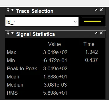
>>the minimum current is -6472e-4 at 0.437 sec
>>the maximum current is 3.0449 at 1.342 sec
FOR Iqr:-
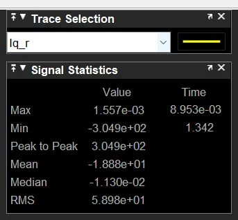
>>the minimum current is --3.0449 at 1.342 sec
>>the maximum current is 1.557e-3 at 8.953e-3 sec
FOR Te and Tl:-
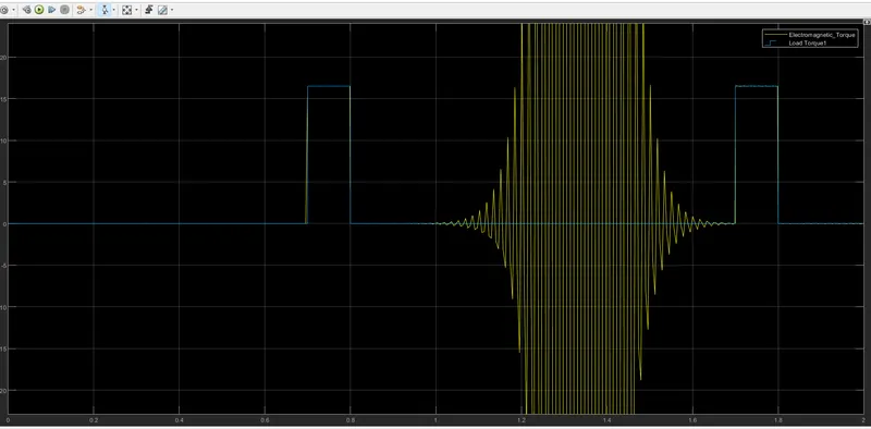
>>From the above graph
>>the top plot is for the Electromagnetic Torque (te)
>>The bottom plot is for the load Torque(Tl)
>>The both Torques consists the follownig Ststistics.
FOR (Te):-
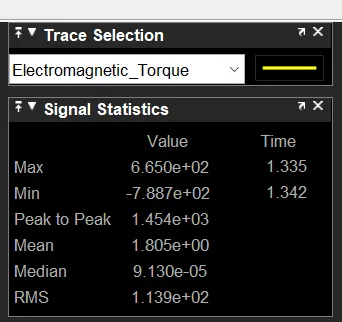
>>The minimum torques is -7.887e2 at 1.342 sec of time.
>>The maximum Torque is 6.650e2 at 1.335 sec of time.
For Load Torque(Tl):-
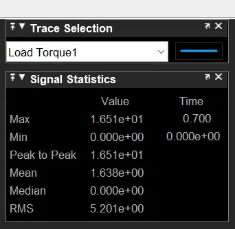
>>The minimum torques is0.00 at 0.0 sec of time.
>>The maximum Torque is 1.65 e1 at 0.700 sec of time.
FOR Wr:-
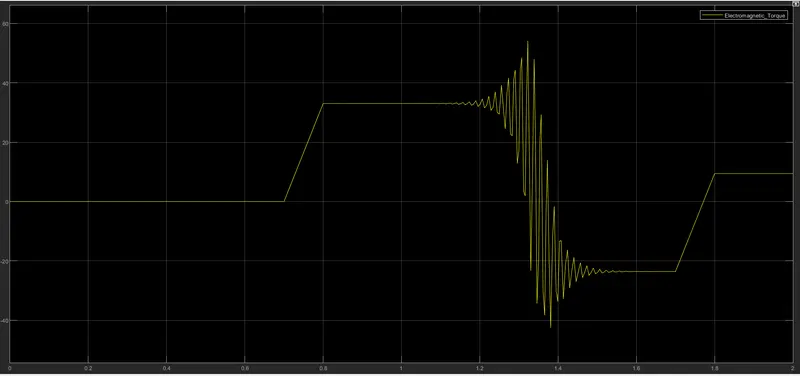
>>The above Graph is for the Rotor angular velocity with folloowing statistics.
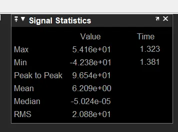
>>The minimum velocity is -4.238e1 rad / sec at 1.381 sec of time.
>>The maximum velocity is 5.416e1 rad / sec at 1.323 sec of time.
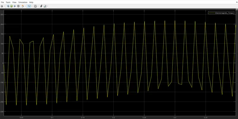
b) Simulate the start-up behaviour of the induction motor represented in the synchronous reference frame. Provide simulation plots of vqs(t),iqs(t),ids(t),iqr(t),idr(t),Te(t),Tl(t)andωr(t).
Simulation Results :-
Vqs:-
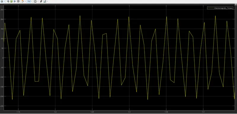
>>from the above graph we can get the graphical representation of duadrature axis stator voltage.
>>this "vqs" having the following statistics.
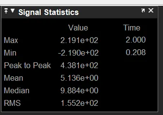
>>The Minimum voltage value is -2.19e2 V at 0.208 sec of time
>>The maximum Voltage value is 2.191e2 at 2.00sec
Is-dq:-
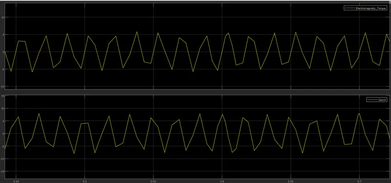
>>from the above graph we can observe that the Top plot is for stator Current in qudrature axis and
>>Below plot is for the stator Current in Direct axis.
>>the both axis consists the following Statistics.
FOR Iqs:-
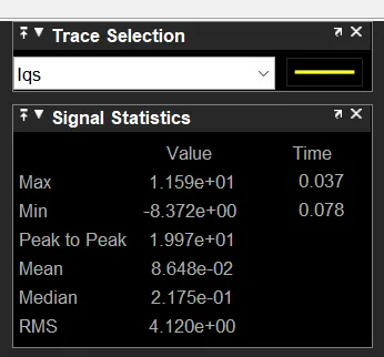
>>the minimum current is -8.372 at 0.078 sec
>>the maximum current is 1.159e1 at 0.037 sec
For Ids:-
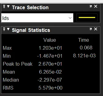
>>the minimum current is -1.467 at 8.121e-3 sec
>>the maximum current is 1.203e1 at 0.068 sec
Ir-dq:-
>>from the above graph we can observe that the Top plot is for Rotor Current in qudrature axis and
>>Below plot is for the Rotor Current in Direct axis.
>>the both axis consists the follownig Statistics.
For Idr:-
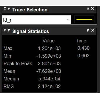
>>the minimum current is -1.599e3 at 0.602 sec
>>the maximum current is1.204e3 at 0.430 sec
For Iq_r:-
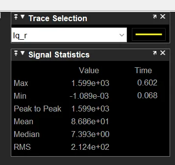
>>the minimum current is --1.089e-3 at 0.668 sec
>>the maximum current is 1.599e3 at 0.602 sec
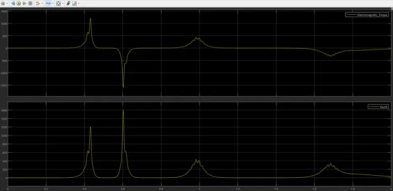
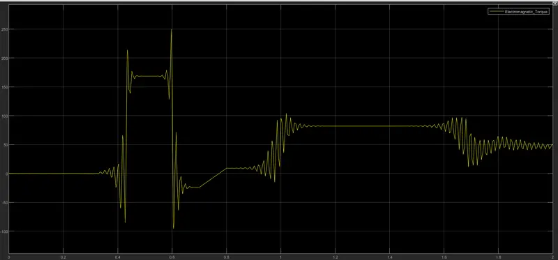
Te and Tl:-
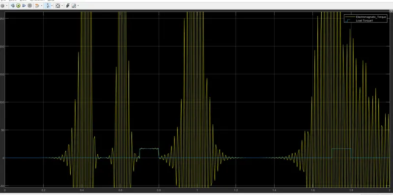
>>From the above graph
>>the top plot is for the Electromagnetic Torque (te)
>>The bottom plot is for the load Torque (Tl)
>>The both Torques consists the following Statistics.
For (Te):-
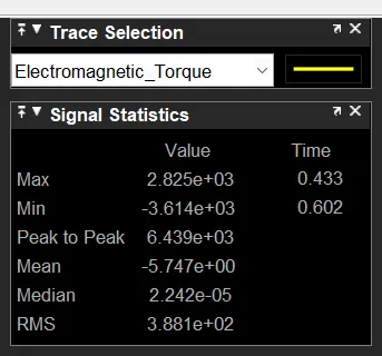
>>The minimum torques is -3.614e3 at 0.602 sec of time.
>>The maximum Torque is 2.825e3 at 0.433 sec of time.
Fir _Tl:-
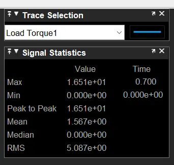
>>The minimum torques is0.00 at 0.0 sec of time.
>>The maximum Torque is 1.65 e1 at 0.700 sec of time.
Wr:-
>>The above Graph is for the Rotor angular velocity with following statistics.
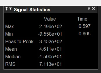
>>The minimum velocity is -9.558e1 rad / sec at 0.605 sec of time.
>>The maximum velocity is 2.496e2 rad / sec at 0.597 sec of time.
C)Simulate the start-up behaviour of the induction motor represented in the rotor reference frame. Provide simulation plots of vqs(t),iqs(t),ids(t),iqr(t),idr(t),Te(t),Tl(t)andωr(t).
Simulation Results:-
Vqs:-
>>from the above graph we can get the graphical representation of quadrature axis stator voltage.
>>this "vqs" having the following statistics.
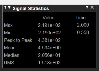
>>The Minimum voltage value is -2.19e2 V at 0.558 sec of time
>>The maximum Voltage value is 2.191e2 at 2.00sec
Is-dq:-
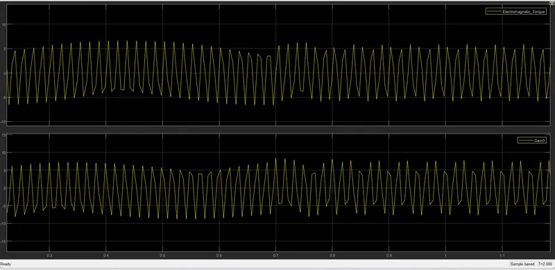
>>from the above graph we can observe that the Top plot is for stator Current in qudrature axis and
>>Below plot is for the stator Current in Direct axis.
>>each axis consists the following Statistics.
For Iqs:-
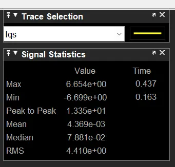
>>the minimum current is -6.699 at 0.163 sec
>>the maximum current is 6.662 at 0.437 sec
For Ids:-
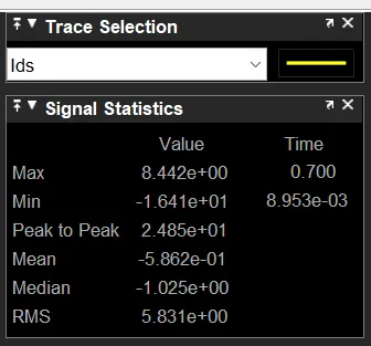
>>the minimum current is -1.699 at 8.953e-3 sec
>>the maximum current is 8.568 at 0.700 sec
Ir-dq:-
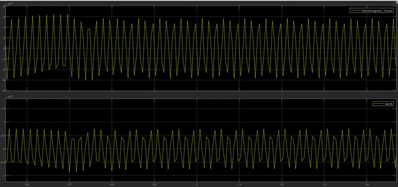
>>from the above graph we can observe that the Top plot is for Rotor Current in quadrature axis and
>>Below plot is for the Rotor Current in Direct axis.
>>each axis consists the following Statistics.
For Idq:-
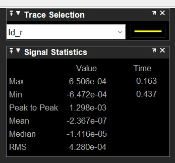
>>the minimum current is -6472e-4 at 0.437 sec
>>the maximum current is 6.506e-4 at 0.163 sec
For Iqr:-
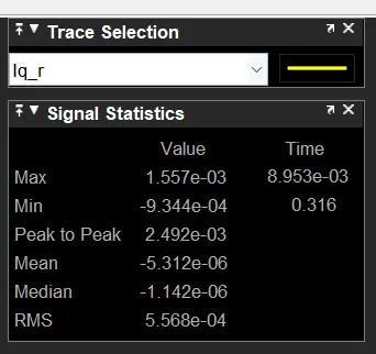
>>the minimum current is -9.30449 at 0.316 sec
>>the maximum current is 1.557e-3 at 8.953e-3 sec
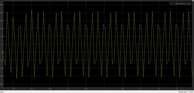
Te and Tl:-
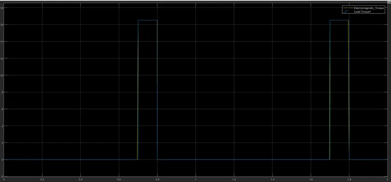
>>From the above graph
>>the top plot is for the Electromagnetic Torque (te)
>>The bottom plot is for the load Torque (Tl)
>>The both Torques consists the following Statistics.
For Te:-
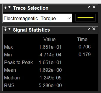
>>The minimum torques is -4.71e-4 at 0.179 sec of time.
>>The maximum Torque is 1.650e2 at 0.706 sec of time.
For _Tl:-
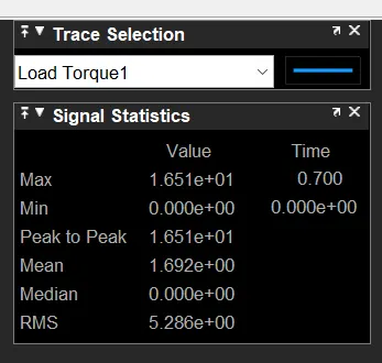
>>The minimum torques is0.00 at 0.0 sec of time.
>>The maximum Torque is 1.65 e1 at 0.700 sec of time.
Wr:-
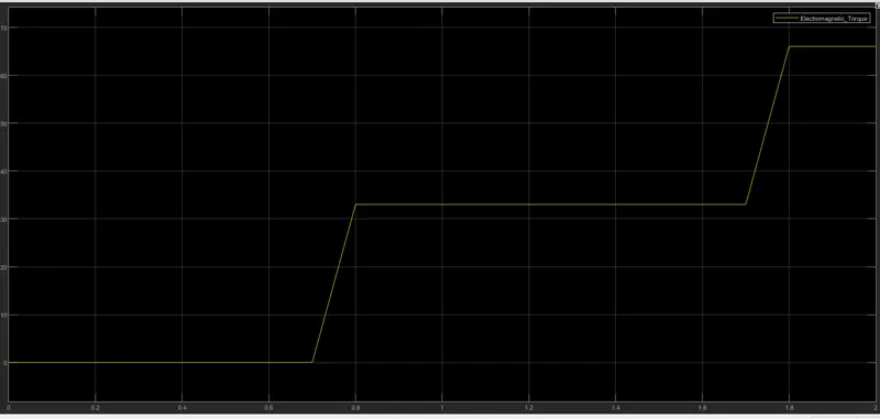
>>The above Graph is for the Rotor angular velocity with following statistics.
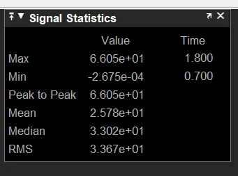
>>The minimum velocity is -2.675e-4 rad / sec at 0.700 sec of time.
>>The maximum velocity is 6.605e1 rad / sec at 1.800 sec of time.
d)Simulate the start-up behaviour of the induction motor represented in the rotor flux reference frame. Provide simulation plots of vqs(t),iqs(t),ids(t),iqr(t),idr(t),Te(t),Tl(t)andωr(t).
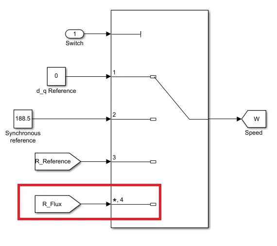
Simulation Results :-
Vqs:-
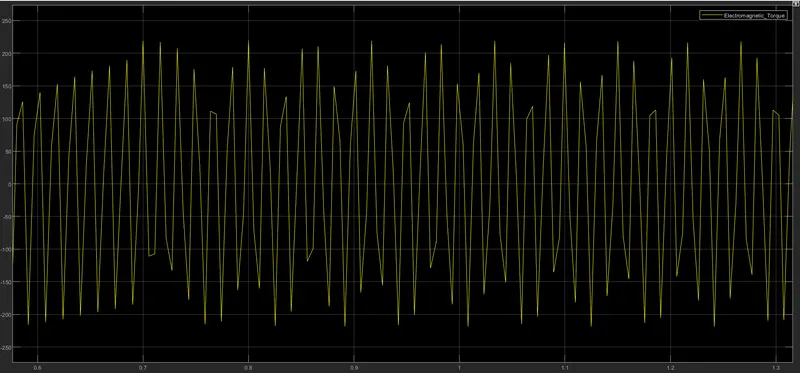
>>from the above graph we can get the graphical representation of quadrature axis stator voltage.
>>this "vqs" having the following statistics
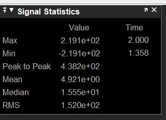
>>The Minimum voltage value is -2.19e2 V at 0.558 sec of time
>>The maximum Voltage value is 2.191e2V at 2.00sec
Is-dq:
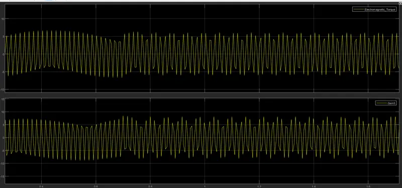
>>from the above graph we can observe that the Top plot is for stator Current in qudrature axis and
>>Below plot is for the stator Current in Direct axis.
>>each axis consists the following Statistics.
For Iqs:-
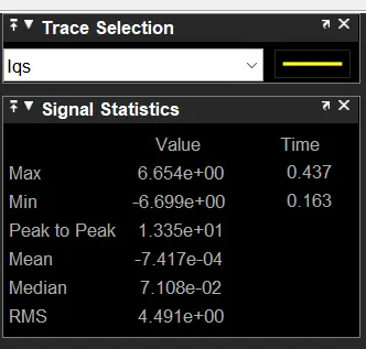
>>the minimum current is -6.699 at 0.163 sec
>>the maximum current is 6.662 at 0.437 sec
For Ids:-
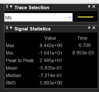
>>the minimum current is -1.641e1 at 8.953e-3 sec
>>the maximum current is 8.442 at 0.700 sec
Ir-dq
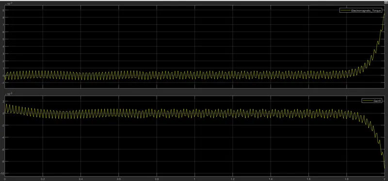
>>from the above graph we can observe that the Top plot is for Rotor Current in quadrature axis and
>>Below plot is for the Rotor Current in Direct axis.
>>each axis consists the following Statistics.
For Idq:-
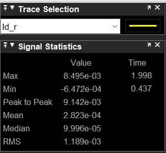
>>the minimum current is -6472e-4 at 0.437 sec
>>the maximum current is 8.0449 at 1.998 sec
For Iqr:-
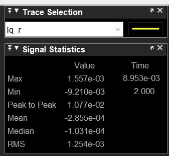
>>the minimum current is -9.210e-3 at 2.00 sec
>>the maximum current is 1.557e-3 at 8.953e-3 sec.
Te and Tl:-
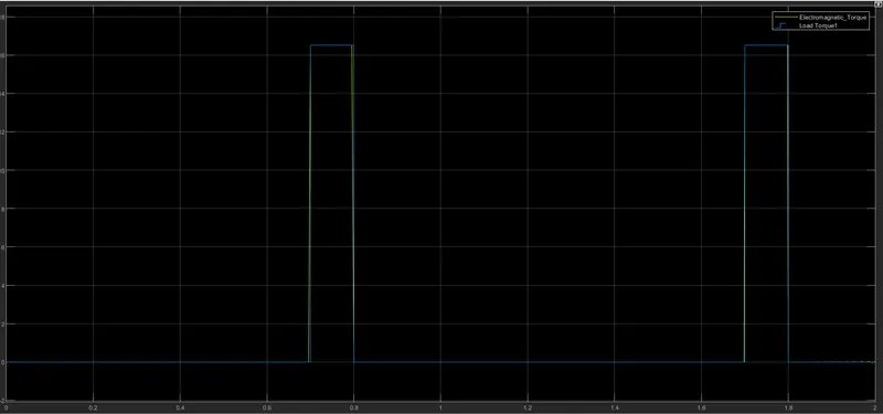
>>From the above graph
>>the top plot is for the Electromagnetic Torque (te)
>>The bottom plot is for the load Torque (Tl)
>>The both Torques consists the following Statistics.
For Te:-
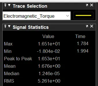
>>The minimum torques is -1.804e2 at 1.994 sec of time.
>>The maximum Torque is 1.650e2 at 1.784 sec of time.
For Tl:-
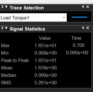
>>The minimum torques is 0.00 at 0.0 sec of time.
>>The maximum Torque is 1.65 e1 at 0.700 sec of time.
Wr:-
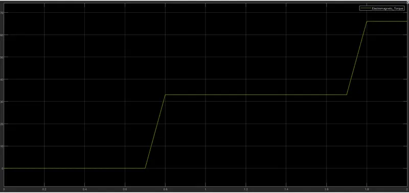
>>The above Graph is for the Rotor angular velocity with following statistics.
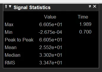
>>The minimum velocity is -2.675e-4 rad / sec at 0.700 sec of time.
>>The maximum velocity is 6.605e1 rad / sec at 1.9.89 sec of time.
Observations:-
From the above all 4 cases we can can conclude that the if we use the speed as in stationary (0 m/sec) and with reference of angular velocity synchronous speed(185.5 r/sec) we getting the very much ossilations in electromagnetic torque that means we can't get the exat value as output while appling the Load torque.
in last 2 cases that is if we are using the speed is as rotor reference and rotor flux reference we get the exatly of Electromagnetic torqe(te) as load torque(Tl) .
Hence ,
we can conclude if we appliyed the Load to the machine that without staring the machine are low RPM of machine we get the output Torque with ossilation nature.